Radar Mast & Final Assembly of Yacht
A REPORT ON
DESIGNING AN YACHT USING SOLIDWORKS
Etikala Surajkumar
Mechanical
CONTENTS
OBJECTIVE
INTRODUCTION
DESIGN METHODOLOGY/APPROACH
DESCRIPTION
3D VIEWS OF AMERICAN CHOPPER
RENDERS OF AMERICAN CHOPPER
OBJECTIVE
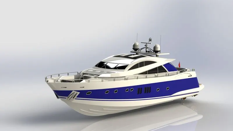
The main objective of this project is to Design a 3D model of an YACHT using SOLIDWORKS and produce photo realistic rendering images using SOLIDWORKS VISUALISE
INTRODUCTION
A yacht is a sailing or power vessel used for pleasure, cruising, or racing. There is no standard definition, so the term applies to such vessels that have a cabin with amenities that accommodate overnight use. To be termed a yacht, as opposed to a boat, such a pleasure vessel is likely to be at least 33 feet (10 m) in length and may have been judged to have good aesthetic qualities.
The Commercial Yacht Code classifies yachts 79 ft (24 m) and over as large. Such yachts typically require a hired crew and have higher construction standards. Further classifications for large yachts are: commercial-carrying no more than 12 passengers, private-solely for the pleasure of the owner and guests, or by the country under which it is registered. A superyacht(sometimes megayacht) generally refers to any yacht (sail or power) longer than 131 ft (40 m).
Racing yachts are designed to emphasize performance over comfort. Charter yachts are run as a business for profit. As of 2020 there were more than 15,000 yachts of sufficient size to require a professional crew.
DESIGN METHODOLOGY
- DESIGNING each part of YACHT i,e..
YACHT HULL,
SUPER STRUCTURE,
PROPELLER, RADAR,
RARAD MAST,
FRONT SEAT,
MIDDLE SEAT,
REAR SEAT.
- ASSEMBLY of YACHT.
- RENDERING the YACHT.
DESCRIPTION
TYPES OF FEATURES
SKETCH:
⦁ A sketch is a 2D profile or cross section. To create a 2D sketch, you use a plane or a planar face. In addition to 2D sketches, you can also create 3D sketches that include a Z axis, as well as the X and Y axes.There are various ways of creating a sketch.
OFFSET:
⦁ Offset one or more sketch entities, selected model edges, or model faces by a specified distance. For example, you can offset sketch entities such as splines or arcs, sets of model edges, loops, and so on.
FILLET:
⦁ It creates a rounded internal or external face on the part. It can fillet all edges of a face, selected sets of faces, selected edges, or edge loops.
EXTRUDE BOSS/BASS:
⦁ Extruded Boss feature adds material to the part model.
EXTRUDE CUT:
⦁ Extrude cut is another feature which helps to remove materials from the 3D model. It is just opposite to extrude boss/base feature, because it cuts a sketch profile while extruding. You can cut in both directions and mainly used for creating holes, channels, slots etc.
LOFTED BOSS/BASS:
⦁ creates a feature by making transitions between profiles. A loft can be a base, boss, cut, or surface. You create a loft using two or more profiles. Only the first, last, or first and last profiles can be points. All sketch entities, including guide curves and profiles, can be contained in a single 3D sketch.
DOME:
⦁ Dome is on the Features toolbar, or click Insert > Features > Dome. ... Click Direction, and select a direction vector from the graphics area to extrude the dome in a direction other than normal to the face. As a direction vector, you can use a linear edge or the vector created by two sketch points.
SPLIT:
⦁ Split tool is used to project an entity sketch, solid, surface, face, plane, or surface spline onto other surfaces or curved/planar faces. We can split faces on multiple bodies with one command.
TRIM ENTITES:
⦁ Trim multiple, adjacent sketch entities by dragging the pointer across each sketch entity.
SHELLS:
⦁ The shell tool hollows out a part, leaves open the faces you select, and creates thin walled features on the remaining faces.
REVOLVE:
⦁ Revolves add or remove material by revolving one or more profiles around a centerline. You can create revolved boss/bases, revolved cuts, or revolved surfaces. The revolve feature can be a solid, a thin feature, or a surface.
MIRROR:
⦁ This tool allows the user to mirror a solid bodies,features and faces about the Axis while creating a part.
DYNAMIC MIRROR:
⦁ This tool allows the user to mirror a sketch about a line while creating the sketch.
APEARANCES:
⦁ This method gives you the choice of applying an appearance to a face, feature, body, part or component. It is sometimes required to apply and edit an appearance's properties to change a parameter such as colour, transparency, or reflectivity.
COMBINE:
⦁ The combine option of the Base Flange/Tab command lets you merge bodies with coplanar faces. To combine sheet metal bodies by adding a base flange in a multibody sheet metal part, move the bodies to be merged to the same plane.
CHAMFER:
⦁ The chamfer tool creates a beveled feature on selected edges, faces, or a vertex. Set the Distance and Angle in the Chamfer Property Manager. A manipulator arrow appears that points in the direction in which the distance is measured.
CIRCULAR PATTERN:
⦁ Circular patterns are used to create multiple instances of one or more features that you can space uniformly around an axis. Pattern instances inherit the feature color of the original feature when the pattern is based on one feature.
LINEAR PATTERN:
⦁ Linear pattern is used to create multiple instances of one or more features that you can space uniformly along one or two linear paths. To create a linear pattern create one or more features to replicate.
SURFACE FEATURES
SURFACE MODELING:
⦁ Surface Modeling is the method of showing or presenting solid objects. The process requires you to convert between different 3D modeling types, such as converting the 3D object to show procedural surfaces, validate imperfections, and apply smoothness.
LOFTED SURFACE:
⦁ Loft Surfaces are surfaces generated by multiple 3D Curves or existing edges creating a smooth tangency between the selected curves. Match Points are created between each selection denoting the orientation and path of the loft surface.
SWEFT SURFACE:
⦁ sweep is a tool that creates a solid, a cut or a surface feature by moving a profile along a path.
FILLED SURFACE:
⦁ The Filled Surface feature constructs a surface patch with any number of sides, within a boundary defined by existing model edges, sketches, or curves, including composite curves. This feature is used to construct a surface to fill a gap in a model.
EXTENDED SURFACE:
⦁ It extends a surface by selecting an edge, multiple edges, or a face. For edges, the surface extends along the plane of the edge For faces, the surface extends along all edges of the face except those connected to another face.
SURFACE KNIT:
⦁ Knit Surface tool is used to combine two or more faces and surfaces into one.
PARTS OF THE YACHT
- PROPELLER
- YACHT RADAR
- BLUEPPRINTS
- YACHT HULL
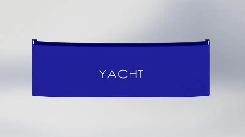
- YACHT BACK DOOR
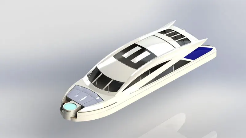
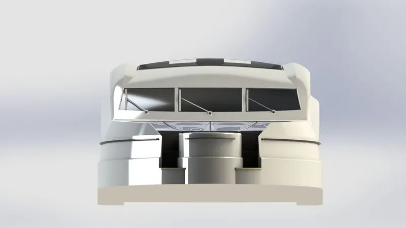
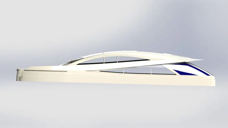
- YACHT SUPER STRUCTUREF
- RONT SEAT
- MIDDLE SEAT
- REAR SEAT
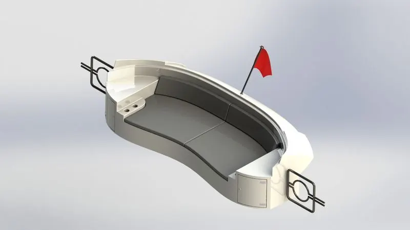
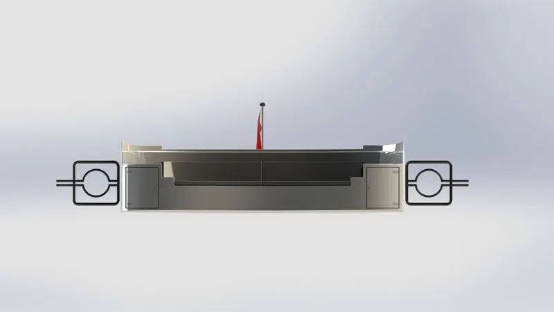
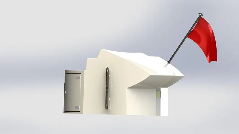
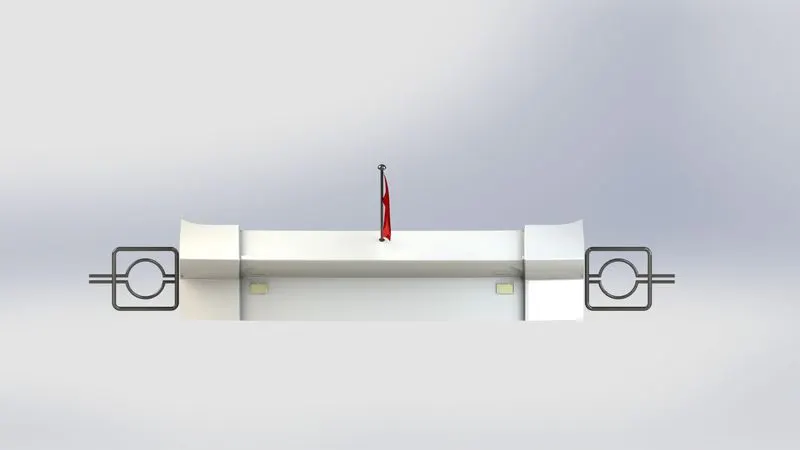
- RADAR MAST
PROPELLER
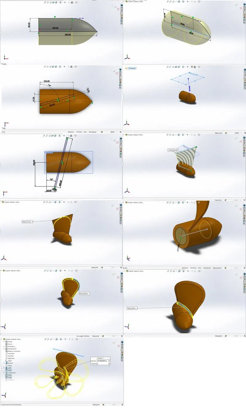
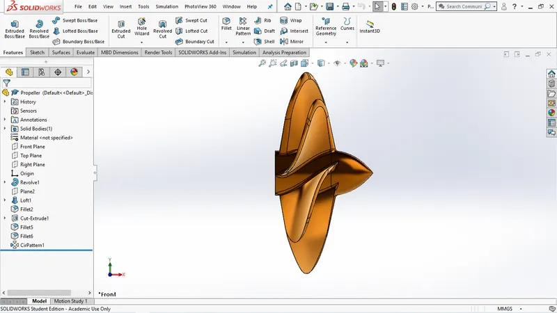
- First the sketch is made as per given dimensions in figure.
- Then the sketch Revolved by selecting the blue line as the axis.
- Then a rectangle is created on the top plane.
- Now a plane is created with reference to the top plane at a distance of 360mm above the top plane.
- Then an another rectangle is created on the newely created plane.
- Now by using the loft feature by selecting the two sketches as profiles a lofted fin is created.
- filleting the two edges of the fin to make a clean round shapes.
- Now extrude cutting the a circular sketch that fits in the rotar shaft.
- filleting the front surface of the fin and joining of the fin.
- Now creating the circular patterns of the fin keeping the instances as 6.
- And finally giving a golden brown appearance to the complete body and saving the file as PROPELLER.
YACHT RADAR
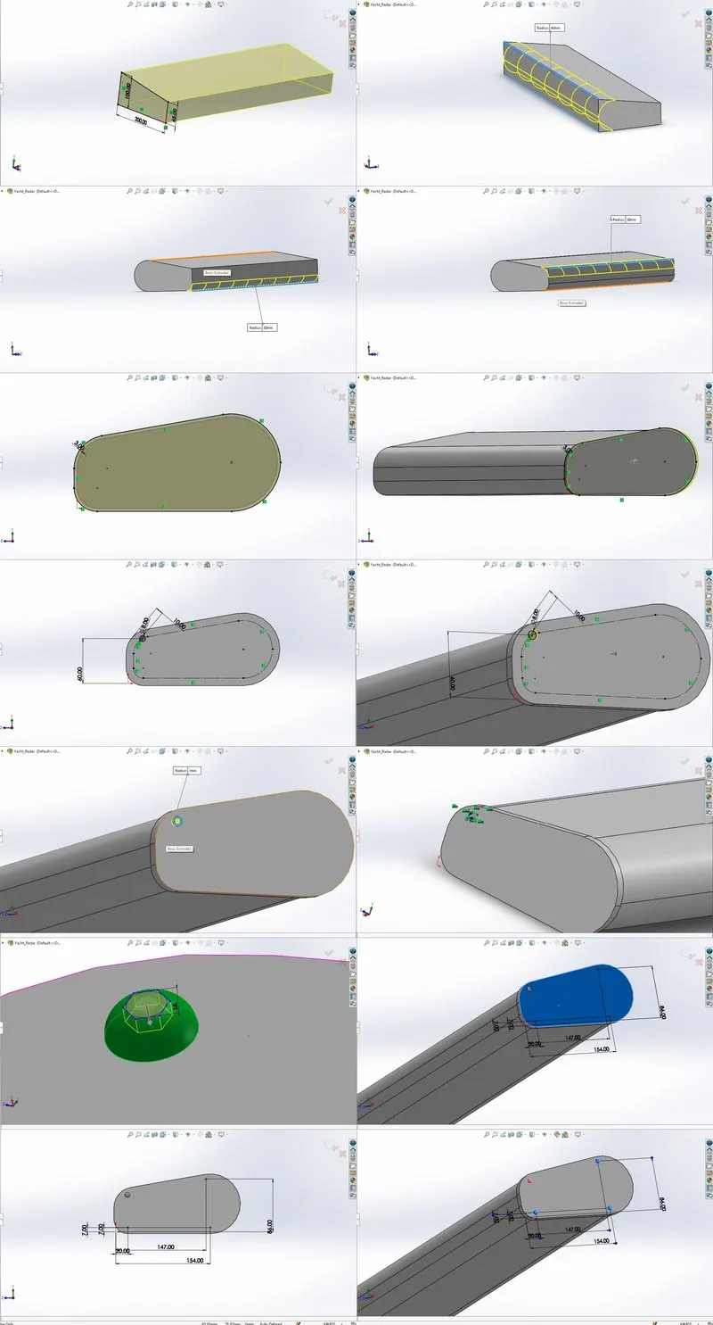
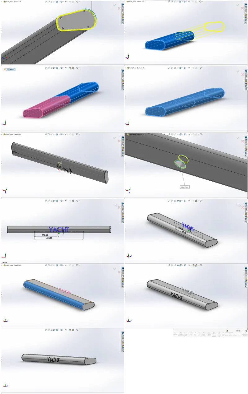
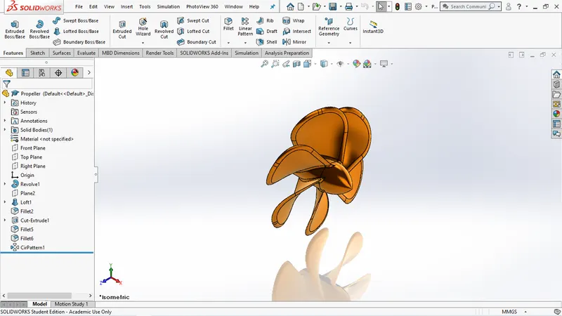
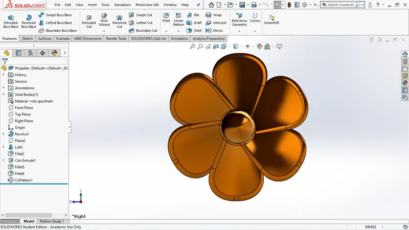
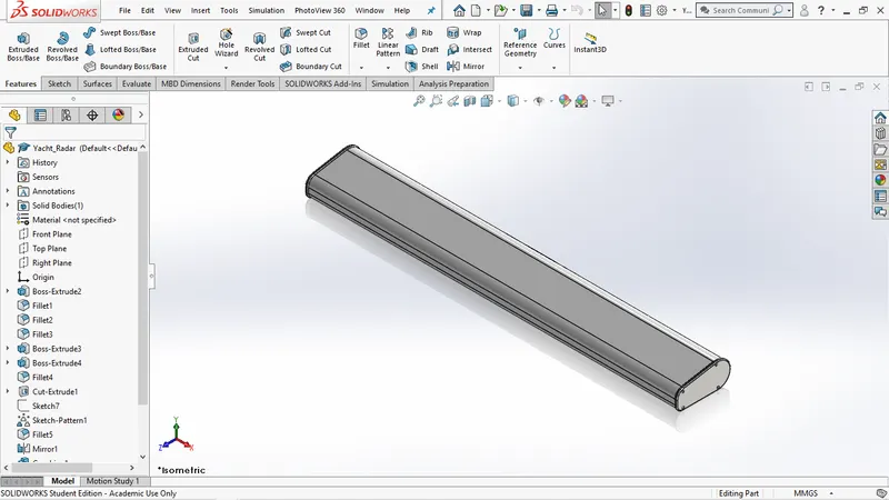
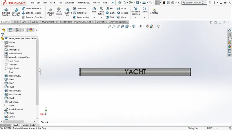
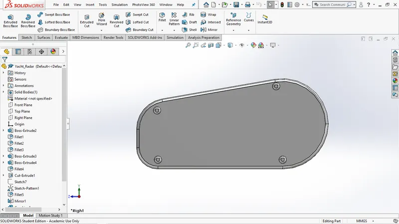
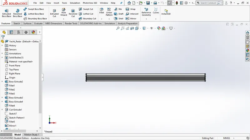
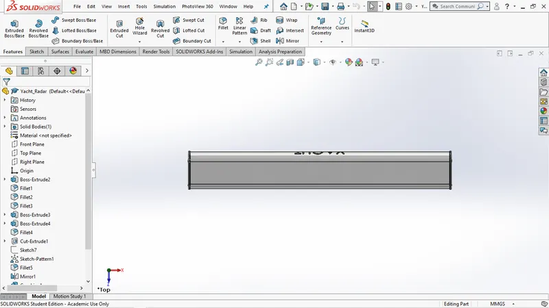
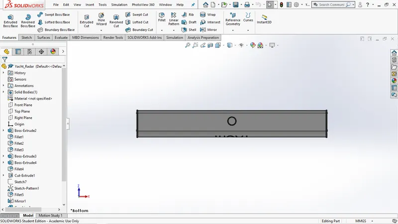
The above images shows the complete 3D design of RADAR from sketching to Solid model
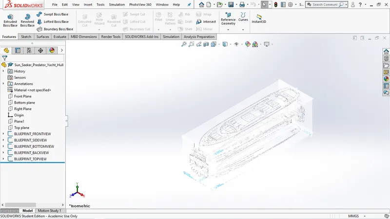
SETTING UP BLUEPRINT
- Picking up the blueprint pictures and setting it up.
- Setting the bule prints is the first step before modeling the yacht.
- They are set in such a way that so that each view of blueprint overlaps and coincide exactly.
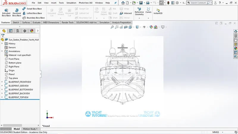
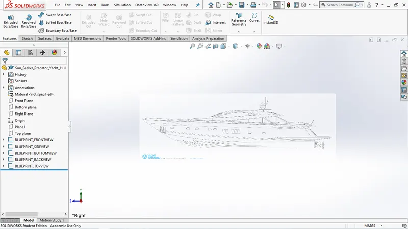
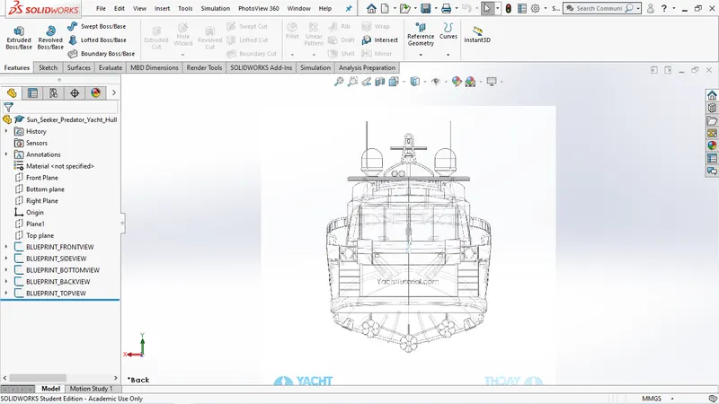
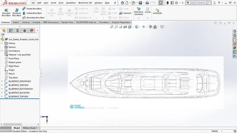
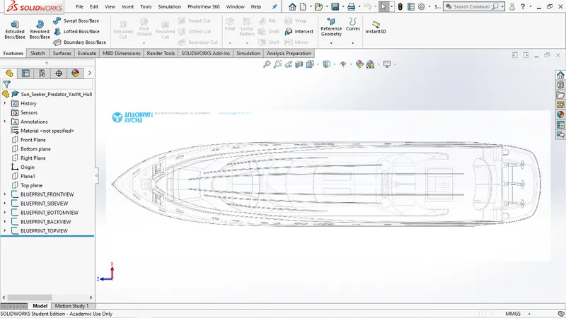
- Setting the bule prints is the first step before modeling the yacht.
- they are set in such a way that so that each view of blueprint overlaps and coincide exactly.
YACHT HULL
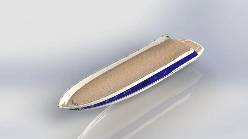
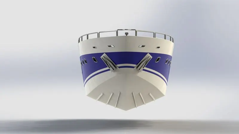
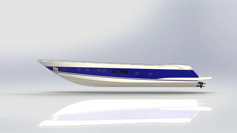
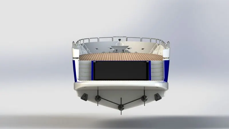
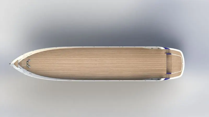
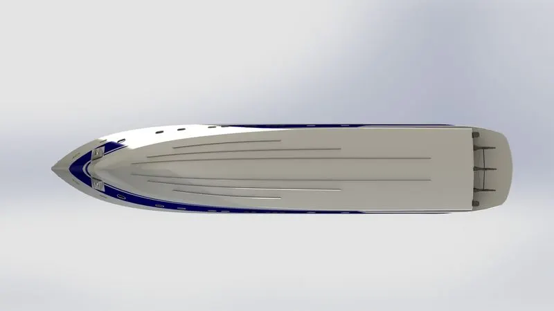
The 'hull' is the portion of your boat that rides both in and on top of the water. The boat hull does not include any masts, sails, rigging, machinery or equipment.
- After setting up the blueprints first the hull part is prepared
YACHT BACK DOOR

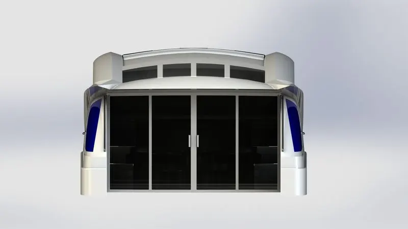
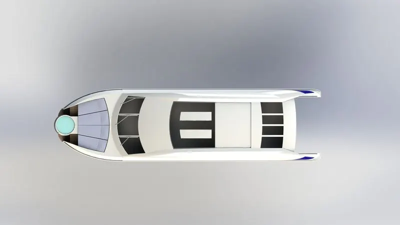
YACHT SUPER STRUCTURE
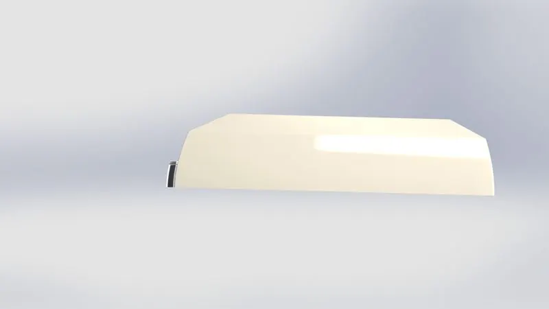
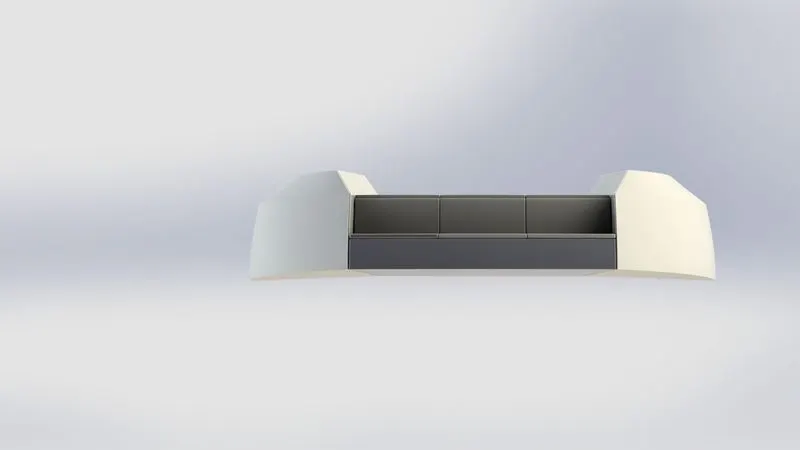
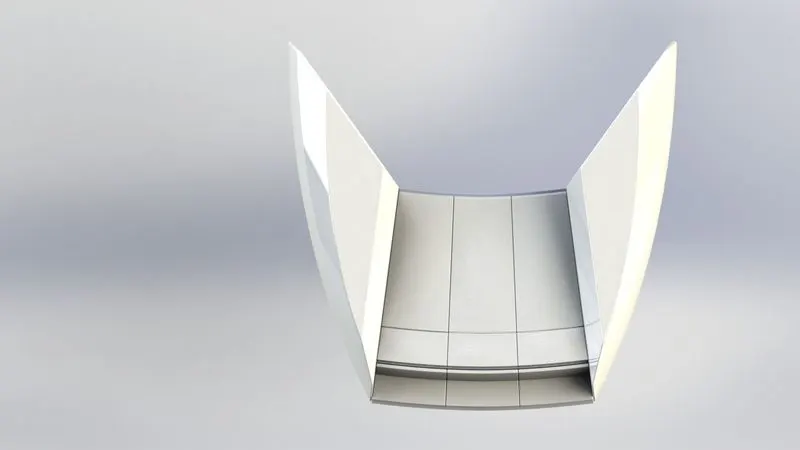
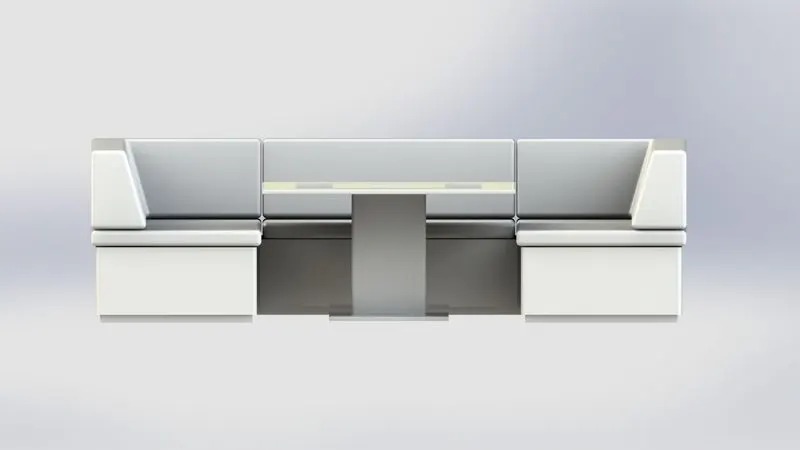
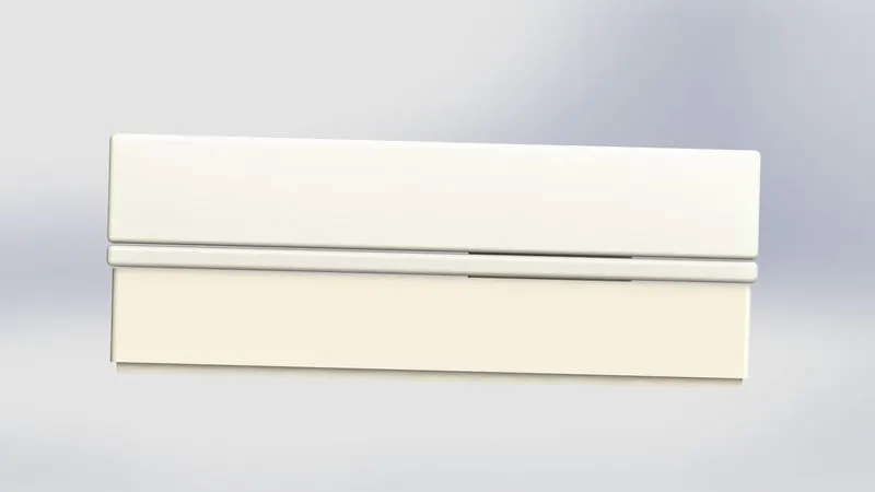
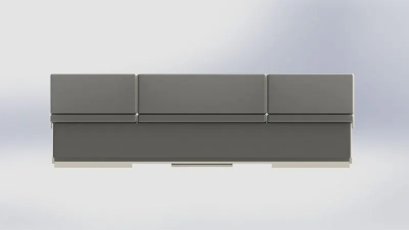
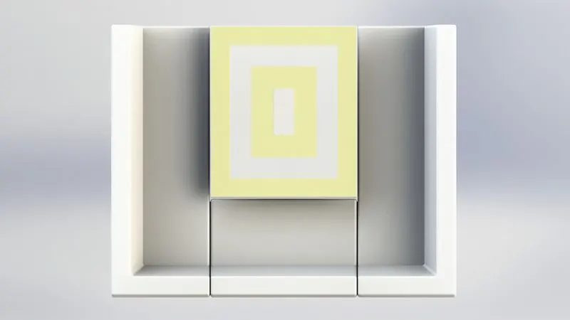
FRONT SEAT
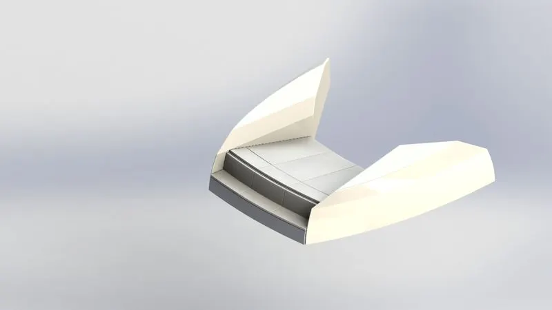
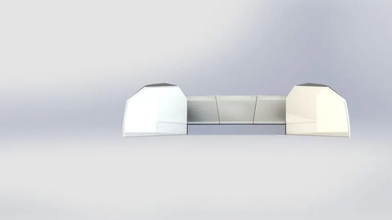
MIDDLE SEAT
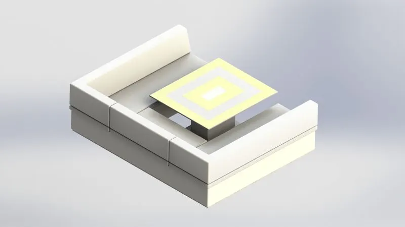
REAR SEAT
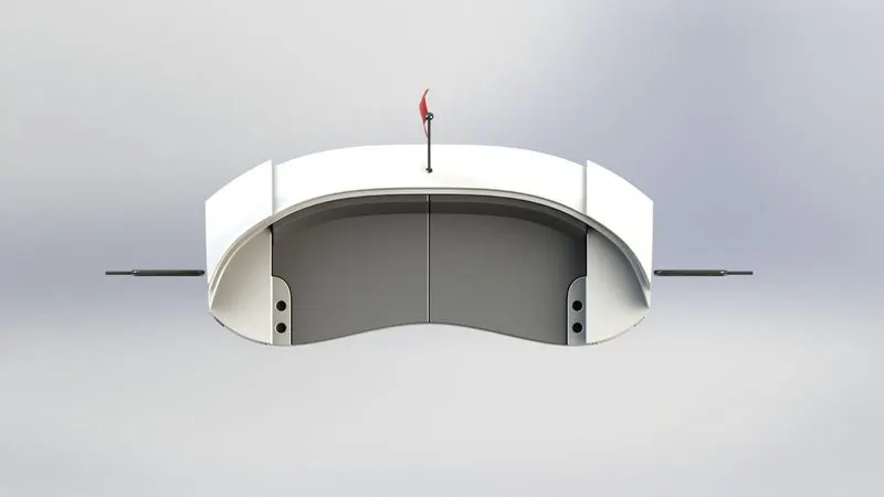
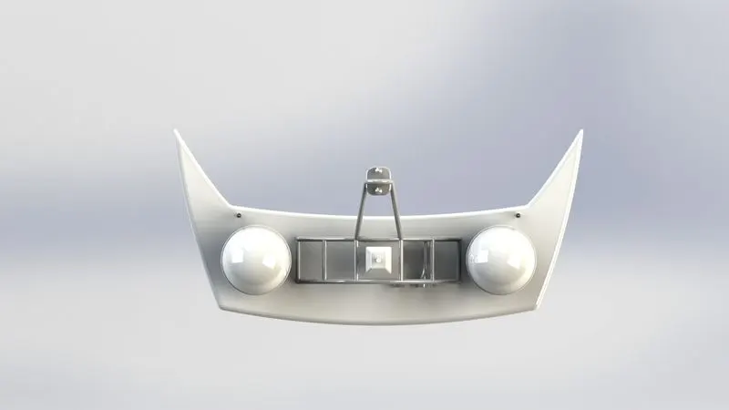
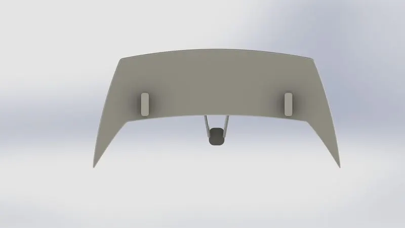
RADAR MAST
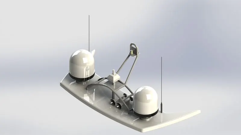
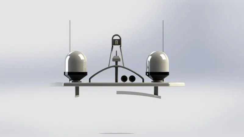
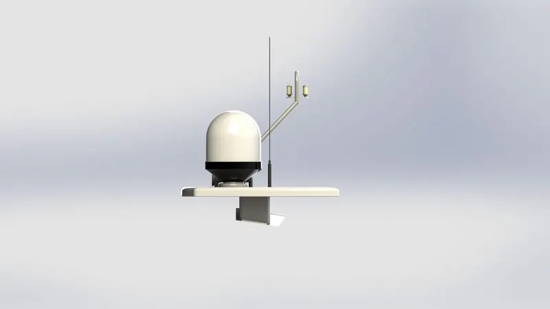
ASSEMBLY OF YACHT
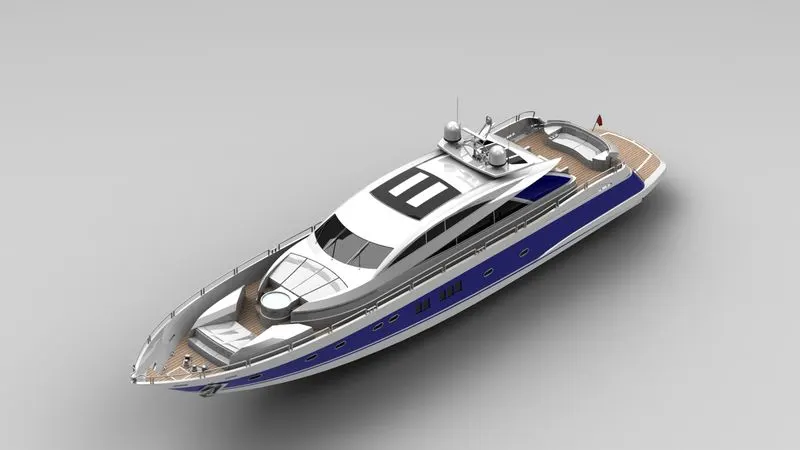
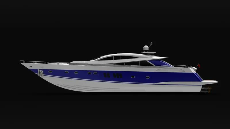
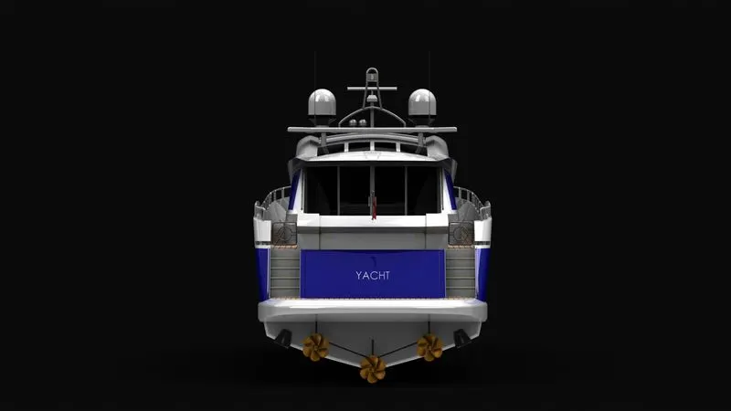
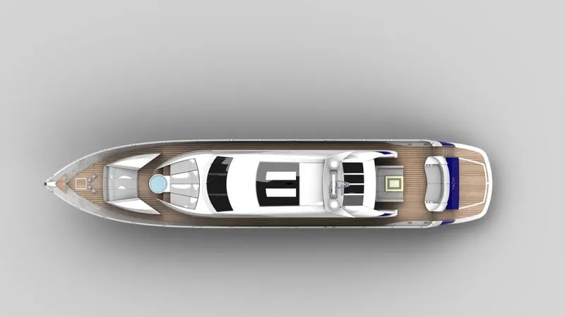
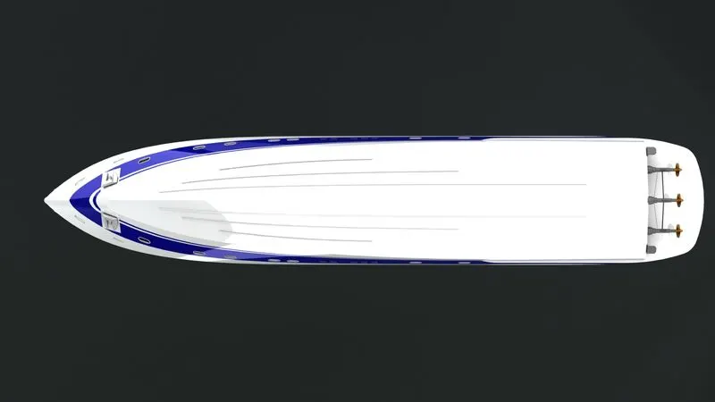
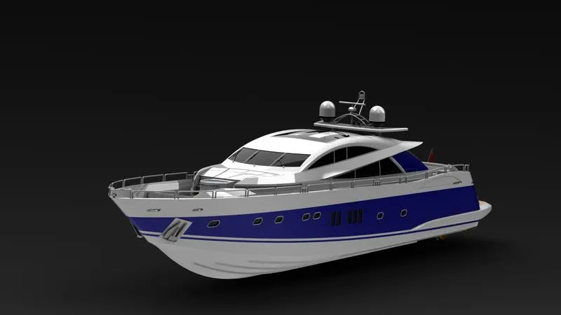
First the HULL is inserted and entered, so that the HULL is inserted in a way that all the planes of the HULL are coincide with all the planes of new assembly file.
Next all the parts are mated with Hull and with the useful mate options like standard, advanced etc and the assembly is done.
RENDERING
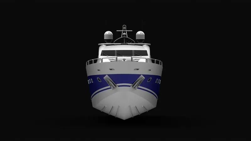
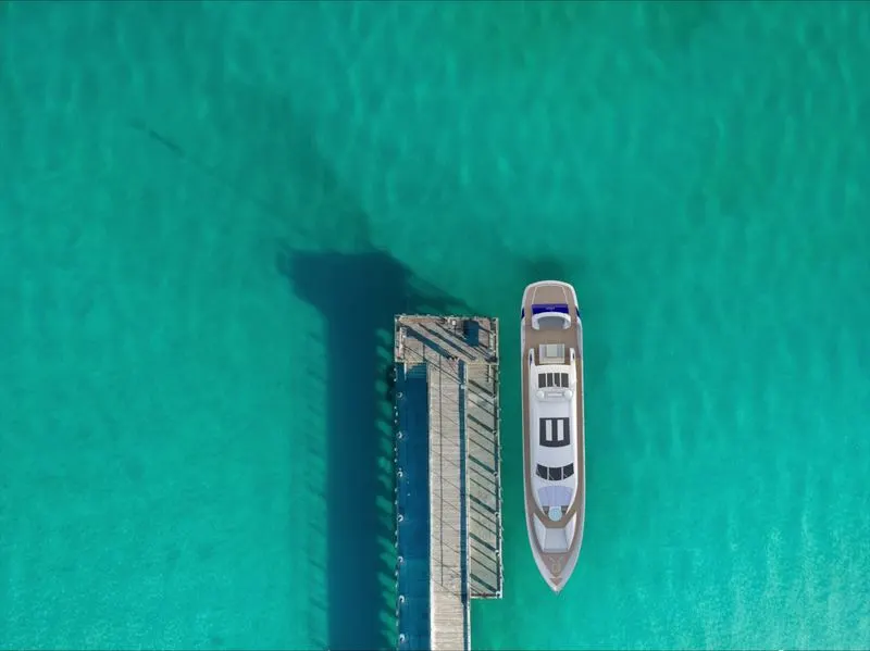
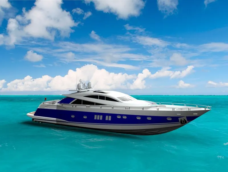
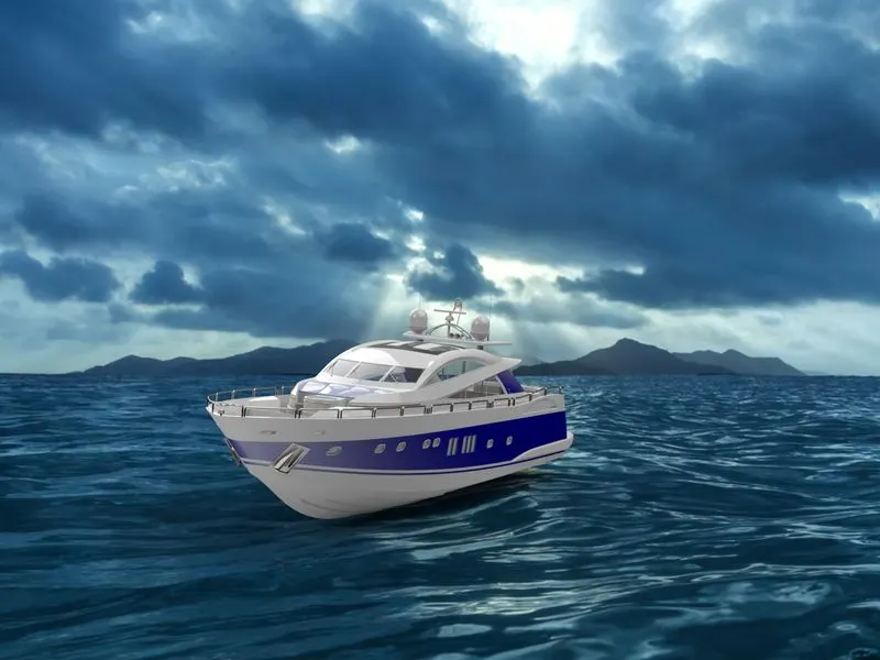
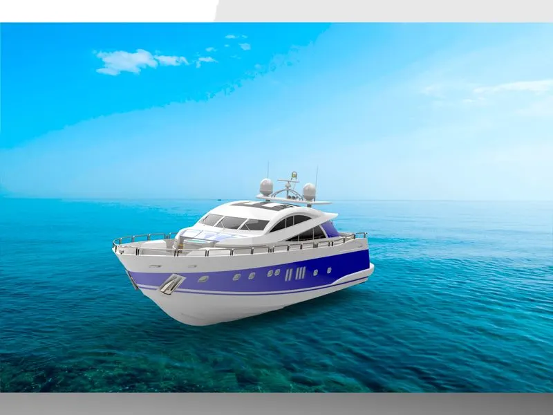
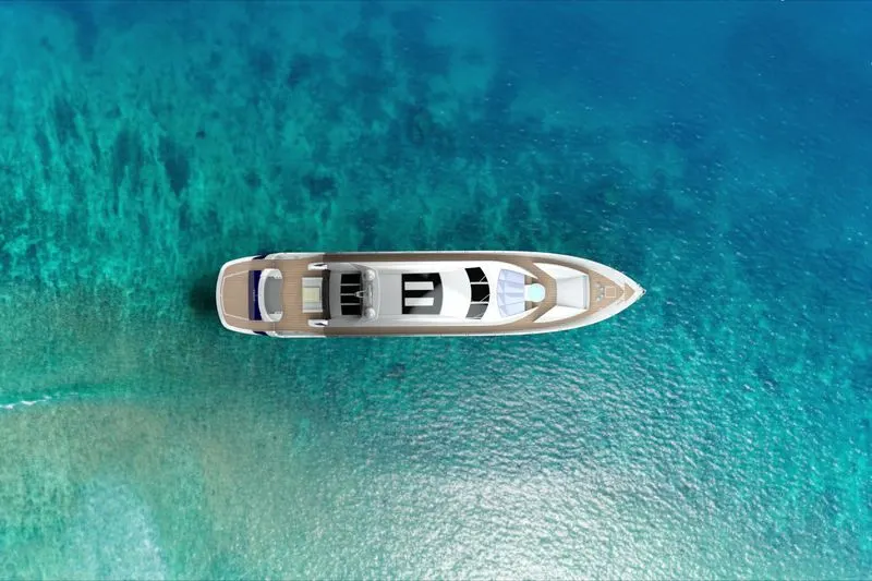
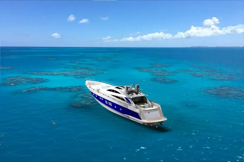
Rendering is the process of generating a photorealistic or non-photorealistic image from a 2D or 3D model by means of a computer program.
CONCLUSION
Hense the YACHT is Assembled and completed with final renderings using SOLIDWORKS PHOTO VIEW 360 and SOLIDWORKS VISUALISE.