MBD Simulation on IC Engine Valve Train
simulation on an IC engine valve Train
Aim:- 1)To Design the parts of the ic engine valve train & assemble them in Solidworks.
2) Run the simulation using the below parameter.
Sr.no cam lift (mm) speed (rpm) material
1 3.5 1500 cast carbon steel
2 6 1500 cast carbon steel
Obtain the follwing
- cam lift
- contact force between
- cam & push rod
- push rod & rocker arm
- rocker arm & valve.
Explain why the contact force between the Rocker arm and valve varies while measuring with respect to the X-direction and measuring with respect to magnitude.
Introduction:-
An IC engine of the valve train is a mechanical system that controls the operation of intake & exhaust valves in an internal combustion engine. The intake valves
control the flow of air or fuel mixture into the combustion chamber. while exhaust valves control the flow of spent exhaust gases out of the combustion chamber once combustion
is completed.
The valvetrain layout is generally dependent on the location of a camshaft. common valve train configuration consists of the cam in a block, overhead camshaft & camless.
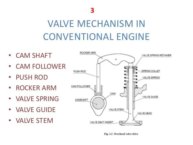
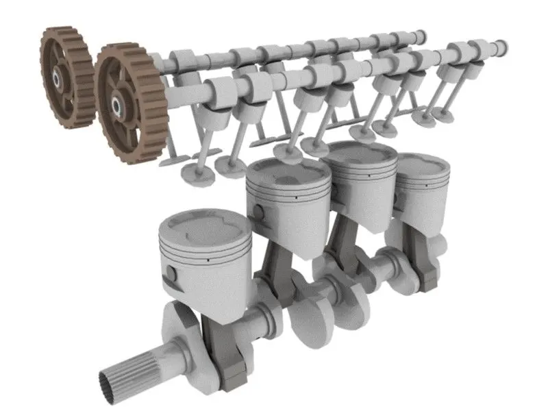
overhead valve drive overhead camshaft engine
Theory:-
The valve train consists of all the components responsible for transferring the rotational movement of the camshaft into the opening & closing of intake & exhaust valves.
there are typical components listed below ordered from the crankshaft to the valves.
STEP 1: Design Of part
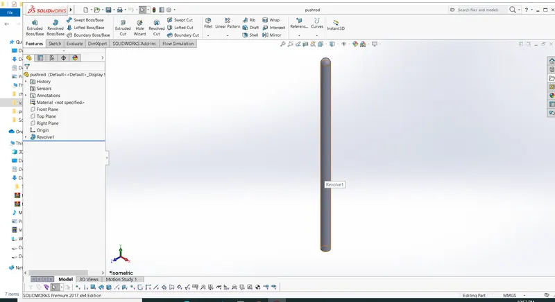
a) Pushrod
Pushrods are long, slender metal rods that are used in valve engines to transfer motion from the crankshaft to the valves. The bottom end of the pushrod is fitted with a lifter.
upon which the camshaft makes contact. The camshaft lobes move the lifter upwards, which moves the pushrod. The top end of the lifter pushes on the rocker arm, which opens the valve.
b) Cam
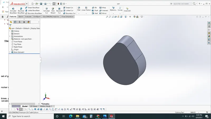
The timing & lift profile of the valve opening events are controlled by the camshaft through the use of a carefully shaped lobe on a rotating shaft. The camshaft is driven by a crankshaft & in the case of a four-stroke engine, it rotates at half the speed of the crankshaft.motion is transferred crankshaft to the camshaft most commonly by a rubber, timing belt, a metallic chain, or set of gears.
c) Rocker arm
According to design, the valves are actuated by rocker arm or bucket tappet. overhead camshaft engine used bucket tappet upon which cam lobes are contacted .overhead valve engine used rocker arm. which are actuated by a rocker pushrod and pivot on a shaft in order to actuate the valves.
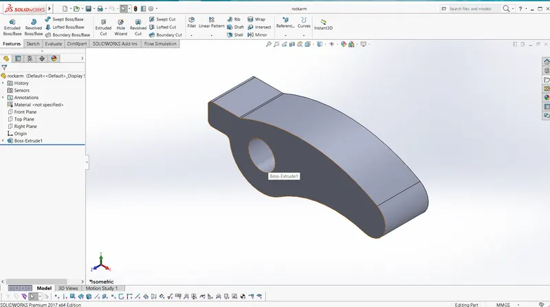
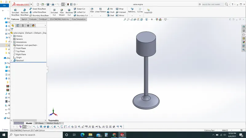
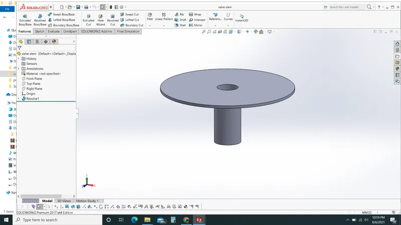
d) valves
There are different types of valves that are used as per their design, most modern engines use poppet valves .although sleeve valves, slide valves & rotary valves have also been used at times. poppet valves are typically opened by the camshaft lobe or rocker arm and closed by a coiled spring called a valve spring. valve float occurs when the valve spring is unable to control the inertia of the valvetrain at high engine speeds.
STEP 2:- ASSEMBLY
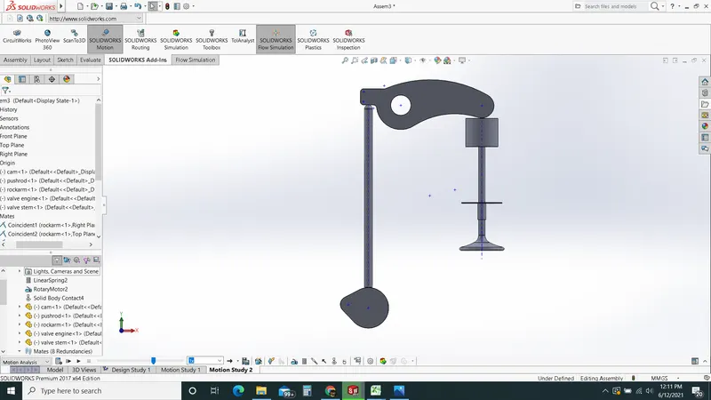
after modeling all parts of ic engine valve train assembly, assembly of all parts take place.
Calculation :
cam lift =(L - R1) +R2
L = Distance between center of two circle
R1 - Radius of the lower circle
R2 - Radioius of the upper circle.
Given - R1 -12.5mm
R2- 5 mm
case1 - cam lift = 3.5
case2 =cam lift = 6
cam lift = (L-R1) +R2 cam lift = (L - R1)+R2
3.5= (L- 12.5)+5 6 = (L-12.5)+5
= 11mm. = 13.5mm.
STEP 3: Simulation &result
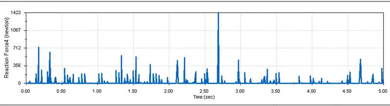
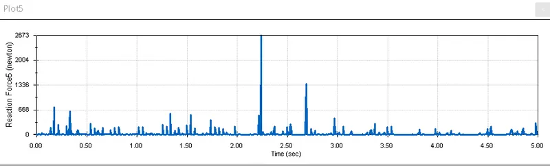
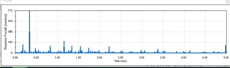
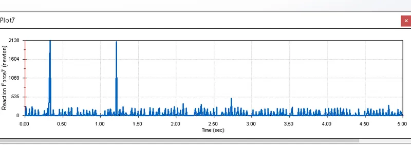
calculate contact force between
CASE 1: cam lift 3.5 mm
cam & Push rod
Pushrod & rocker arm
Rocker arm & valve
CASE 2: CAM LIFT 6MM
cam & Pushrod
Pushrod & rocker arm
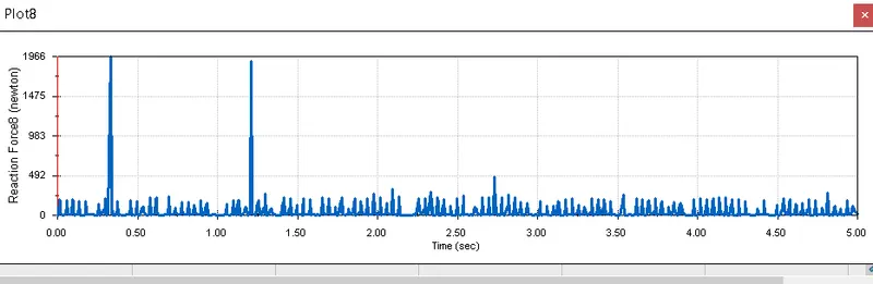
Rocker arm & valve
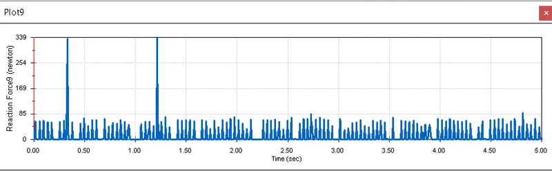
Explain why the contact force between the Rocker arm and valve varies while measuring with respect to the X-direction and measuring with respect to magnitude.
Explanation: The contact force between the rocker arm & valve varies while measuring with respect to the x-direction& magnitude because there are sudden contact force increases.at this min point of contact, cam lift maximum so contact force maximum & varies according to the position.
Results & Conclusion:
1) In the simulation of the ic engine valve train we obtain the result cam lift & contact force between assembly parts rocker arm, pushrod, cam & valve engine.
2) The variation in result of cam lift obtain in while simulation of contact force between rocker arm & valve. a sudden change of result obtains contact force variation occurs, with respect to x-direction & measuring with respect to magnitude.
3) The distance between two centers(L) for cam obtain for 2 cases by using cam lift formula
CAM Lift = (L-R1)+R2
1) L =11mm 2) L= 13.5mm