Flow over an airfoil
Aim: - To Model Flow over a NACA0017 Airfoil & compare the Lift & Drag Force Using Different Angle Of Attack.
Introduction:
An Airfoil is the cross-sectional shape of an object whose motion through a gas is capable of generating significant lift such as a wing, a sail, blades of a propeller, a rotor, or a turbine. a solid body moving through a fluid produces an aerodynamic force. The component of force perpendicular to the relative freestream velocity is called Lift. The component of force parallel to the relative freestream velocity is called Drag. Airfoils can be designed for use at different speeds by modifying their geometry.
Foils of similar Function Designed with water as the working fluid are called hydrofoils, for example -dolphin flipper fin. The lift on an airfoil is primarily the result of its Angle of Attack. This is an example of various airfoils in nature & various vehicles.
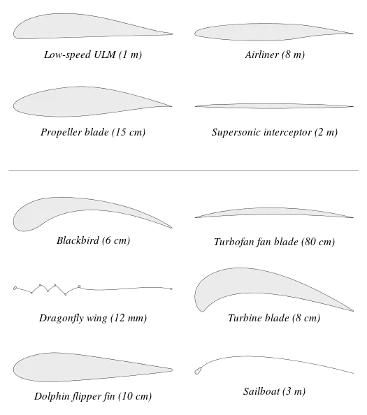
The thin airfoil theory is a simple theory that relates Angle of Attack. for incompressible and inviscid flows.
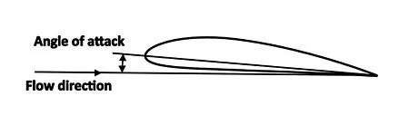
Angle of Attack
An Angle of Attack(`α`) is the angle between the reference line on a body and the vector representing the relative motion between the body & fluid through which it is moving. In aerodynamics angle of attack specifies the chord line of the wing of a fixed-wing aircraft and the vector representing the motion between the aircraft and the atmosphere.
Angle Of Attack
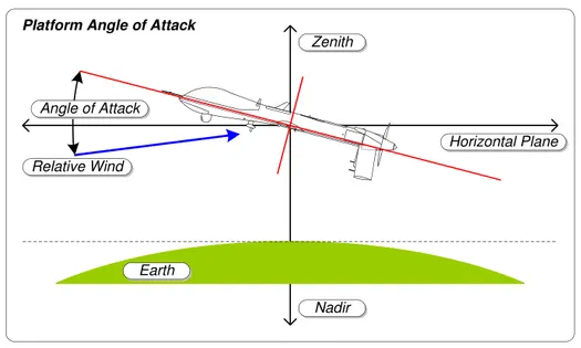
A symmetrical wing has Zero lift at 0 Degrees angle of attack. the lift curved is also influenced by the wing shape, including its airfoil section and wing Platform.
Platform Angle of Attack
Explanation:
Make sure the unit is MKS.
- Download the file of NACA 0017 Airfoil from the below link. http://airfoiltools.com/airfoil/naca4digitMNaca4DigitForm%5Bcamber%5D=0&MNaca4DigitForm%5Bposition%5D=0&MNaca4DigitForm%5Bthick%5D=17&MNaca4DigitForm%5BnumPoints%5D=81&MNaca4DigitForm%5BcosSpace%5D=0&MNaca4DigitForm%5BcosSpace%5D=1&MNaca4DigitForm%5BcloseTe%5D=0&yt0=Plot
- go the Solidworks and select a new part file then click on the insert menu & go to the curve Option after that select curve through XYZpoint.
- After that one dialogue box will appear to select the browse option and open NACA 0017 file ( make sure the file should be in txt. format)
- then coordinate will be displayed on dialogue then click the Ok button.
- Click on the front plane normal sketch option to convert the entity option & select curve to make a sketch of the curve.
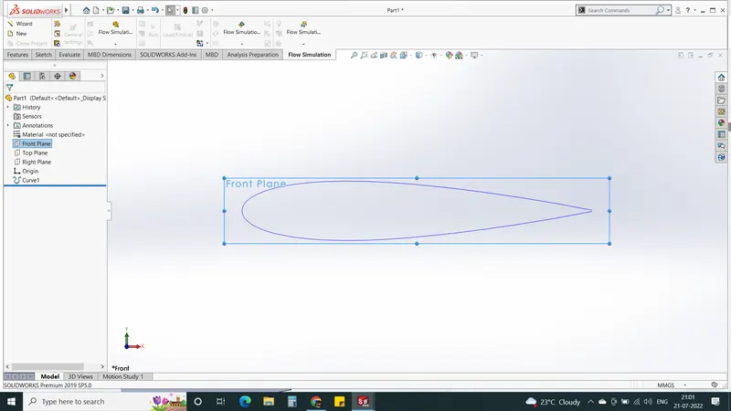
- the curve is an open end close the curve by line command.
- Now Provide Angle to the curve by move entity Option, select Rotate entity then extrude the curve
- The thickness Of an Airfoil is 0.0002m
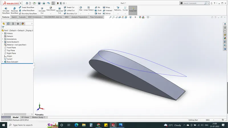
Then Apply the steps Of Flow Simulation ( AOA Analysis)
The parameter should be considered.
- Unit System should be MKS
- The analysis type should be External flow analysis
- Physical parameter Time-dependent. Total analysis time - 5sec & output time step 1s.
- Project Fluid - Air
- Velocity Parameter - velocity in X direction - 600m-s.
- To study the flow analysis we need to select the quantity which we need to study. In order to study the quantity, we need to right-click on the goal and select insert global goals after that select the quantity which you want to study.
- Similarly, study for the surface Goals.
- In order to provide local mesh Right click on Mesh and insert local mesh & select the surface of the airfoil then click ok.
- Now click Run Option Select the New calculation option & click Ok to Start Run Flow simulation.
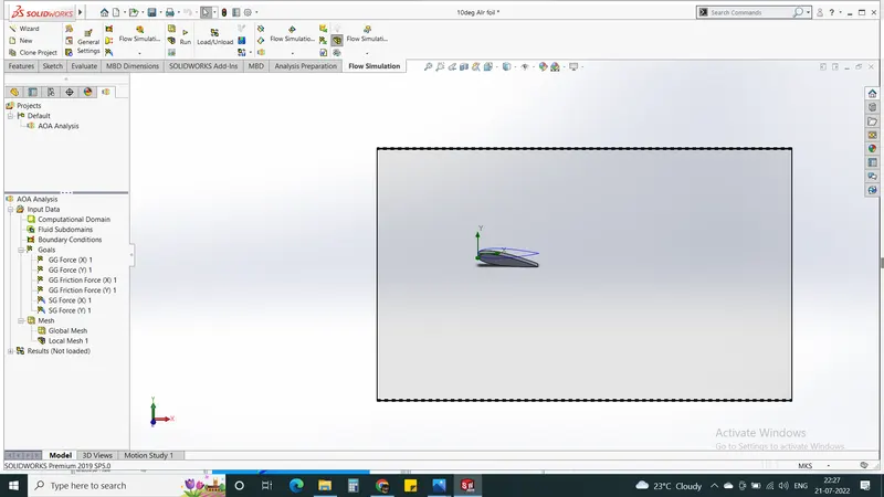
Result:
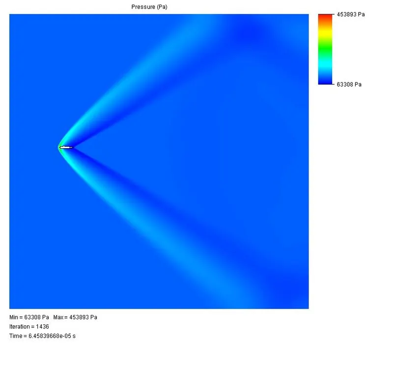
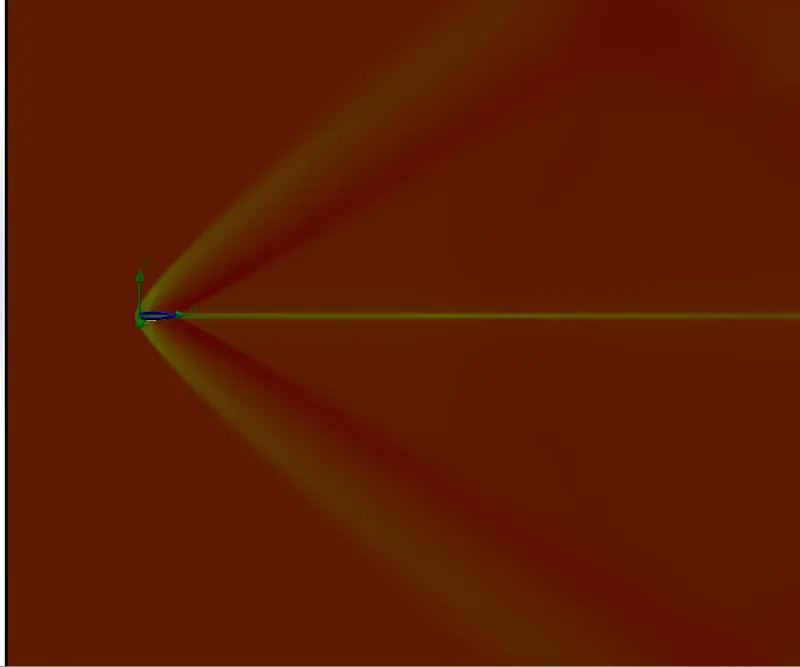
Case 1. When the angle of attack is zero
Pressure plot
Velocity Plot
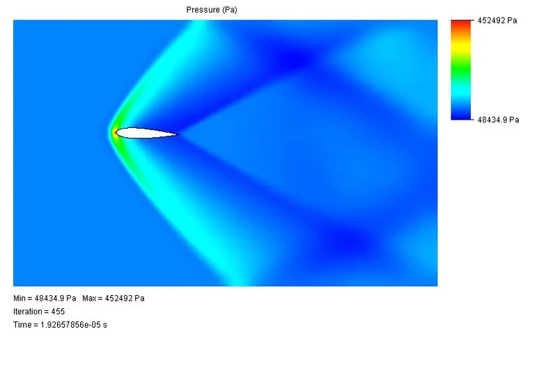
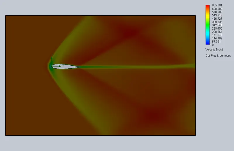
Case 2. When the angle of attack is Two degree.
Pressure plot
Velocity Plot
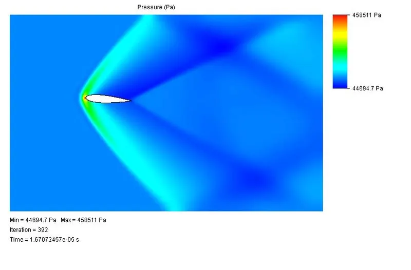
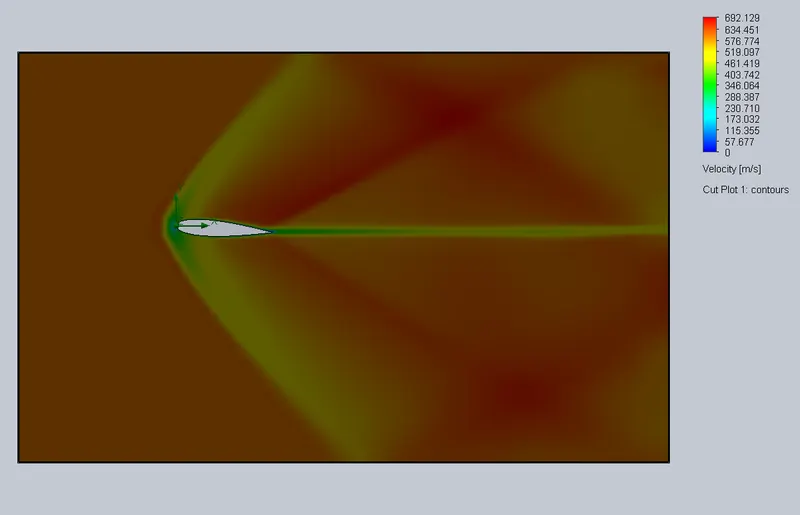
Case 3. When the angle of attack is Four degrees
Pressure plot
Velocity lot
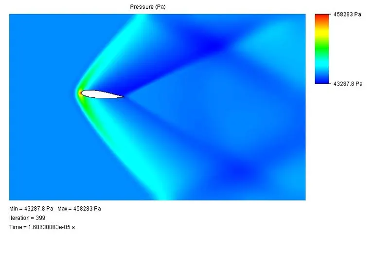
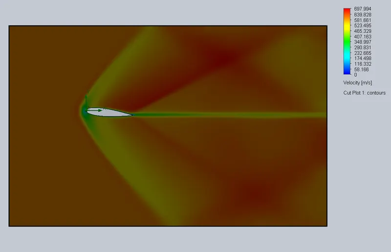
Case 4. When the angle of attack is six degrees
Pressure plot
Velocity Plot
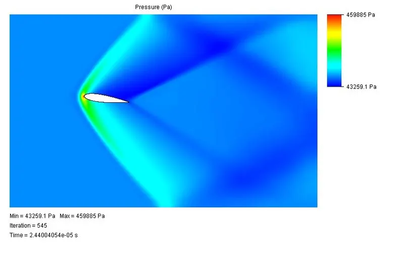
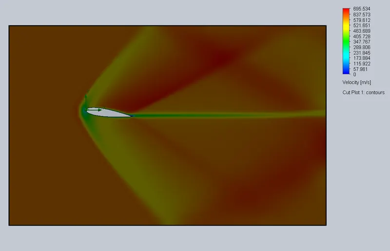
Case 4. When the angle of attack is Eight degrees
Pressure plot
Velocity Plot
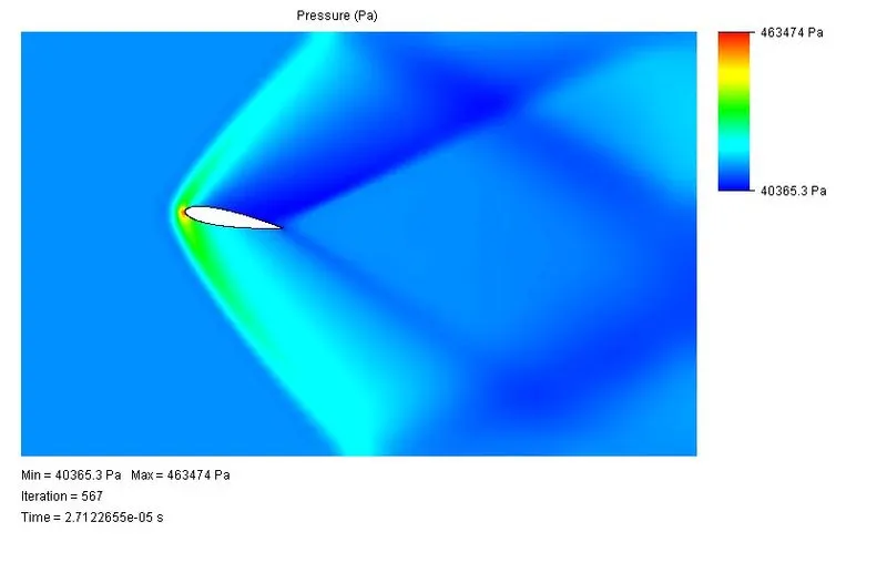
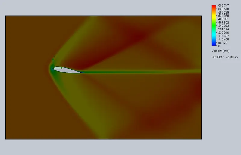
Case 4. When the angle of attack is Ten degrees
Pressure plot
Velocity plot
Comparison Of Lift & Drag Force
| Angle of Attack | Goal Name | Unit | Value | Averaged Value | Minimum Value | Maximum Value | Progress [%] | Use In Convergence | Delta | Criteria |
| 0 | SG Force (X) 1 | [N] | 0.00157 | 0.001564076 | 0.001555581 | 0.001571 | 100 | Yes | 7.32E-07 | 1.94E-05 |
| SG Force (Y) 1 | [N] | 9E-06 | 6.53256E-06 | -4.40014E-06 | 1.53E-05 | 34.8 | Yes | 1.49E-06 | 5.2E-07 | |
| 2 Deg | SG Force (X) 1 | [N] | 0.002 | 0.002 | 0.002 | 0.002 | 100 | Yes | 2.56E-06 | 1.91E-05 |
| SG Force (Y) 1 | [N] | 6.48E-04 | 6.49E-04 | 6.38E-04 | 6.65E-04 | 100 | Yes | 2.94E-06 | 1.24E-05 | |
| 4 | SG Force (X) 1 | [N] | 0.002 | 0.002 | 0.002 | 0.002 | 100 | Yes | 3.77E-06 | 2.13E-05 |
| SG Force (Y) 1 | [N] | 0.001 | 0.001 | 0.001 | 0.001 | 100 | Yes | 5.03E-06 | 2.40E-05 | |
| 6 | SG Force (X) 1 | [N] | 0.002 | 0.002 | 0.002 | 0.002 | 100 | Yes | 1.24E-06 | 2.50E-05 |
| SG Force (Y) 1 | [N] | 0.002 | 0.002 | 0.002 | 0.002 | 100 | Yes | 2.56E-06 | 3.47E-05 | |
| 8 | SG Force (X) 1 | [N] | 0.002 | 0.002 | 0.002 | 0.002 | 100 | Yes | 1.19E-06 | 2.85E-05 |
| SG Force (Y) 1 | [N] | 0.003 | 0.003 | 0.003 | 0.003 | 100 | Yes | 1.96E-06 | 4.45E-05 | |
| 10 | SG Force (X) 1 | [N] | 0.002 | 0.002 | 0.002 | 0.002 | 100 | Yes | 7.62E-07 | 3.39E-05 |
| SG Force (Y) 1 | [N] | 0.003 | 0.003 | 0.003 | 0.003 | 100 | Yes | 1.06E-06 | 5.39E-05 |
Conclusion:
- The lift & Drag Force Increases with the increasing Angle Of An Attack.
- The increase in Maximum Pressure & Velocity is not very Significant with the angle of attack being increased in the Airfoil.
- The thickness of an airfoil is min, so there not much change was observed in the result.
- With an Increase Angle Of Attack the velocity of the Air over the airfoil increases.