MBD Simulation on a Piston Assembly
MBD Simulation On a piston Assembly
Aim:- a)To design & assemble the parts in Solidworks.
b) To study motion analysis using three different conditions.
c) obtain the linear displacement of the piston head in all three cases.
Sr.no Wrist Pin offset crank speed(rpm)
1 '0' 10
2 '10'mm positive 10
3 '10' mm negative 10
Introduction:-
A piston is a component of reciprocating & engines, reciprocating pumps, gas compressors, hydraulic & pneumatic cylinders among other similar mechanism. it is a moving component that is contained by a cylinder & is made gas-tight by piston rings. in an engine, its purpose is to transfer force from expanding gas in the cylinder to the crankshaft via the piston rod or connecting rod. in some engines, the piston act as a valve by covering & uncovering ports in the cylinder. various application is used piston assembly such as hydraulic cylinder, shock absorber, fire piston & syringe.
Theory:
The piston is used in various types of engines as per their requirement. such as trunk pistons, crosshead piston, slipper piston, deflector piston & racing piston .piston assembly consist of various parts complete cycle.piston, crank, gudgeon pin (wrist pin), end cap & connecting rod.
STEP 1:- Design of Part
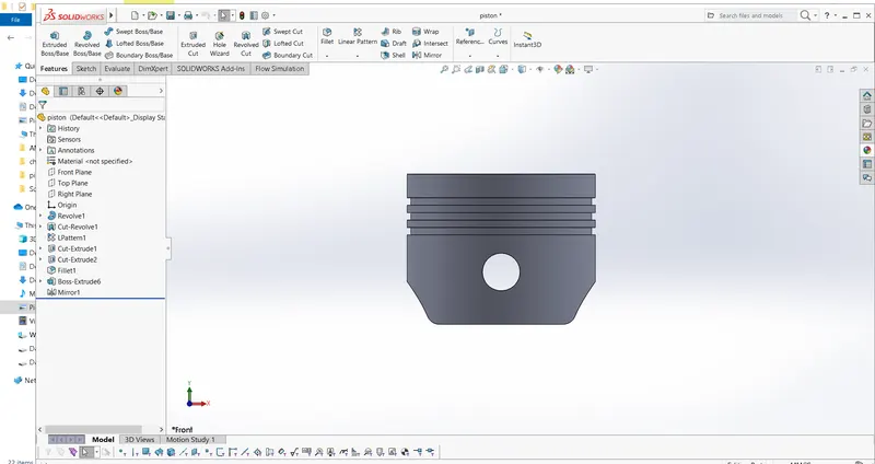
Piston
The piston is a moving disk enclosed in a cylinder that is made gas-tight by piston rings. A piston aids in the transformation of heat energy into mechanical work& vice versa. pistons are a key component of heat engines. pistons are worked by transforming force output by expanding gas cylinder to a crankshaft which provides rotational momentum to a flywheel such system is known as ' reciprocating engine'.
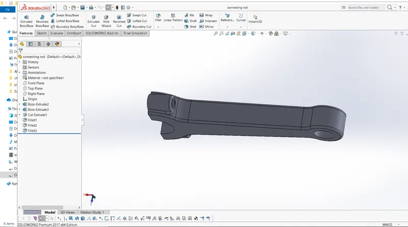
connecting rod & end cap
A connecting rod is the part of a piston that end connects the piston to the crankshaft together with the crank. the connecting rod converts the reciprocating motion of the piston into the crankshaft. The connecting rod is required to transmit the compressive & tensile force from the piston.in an internal combustion engine, it allows pivoting on the piston end & rotation on the shaft end.its most common usage allows internal combustion engine & steam engine.
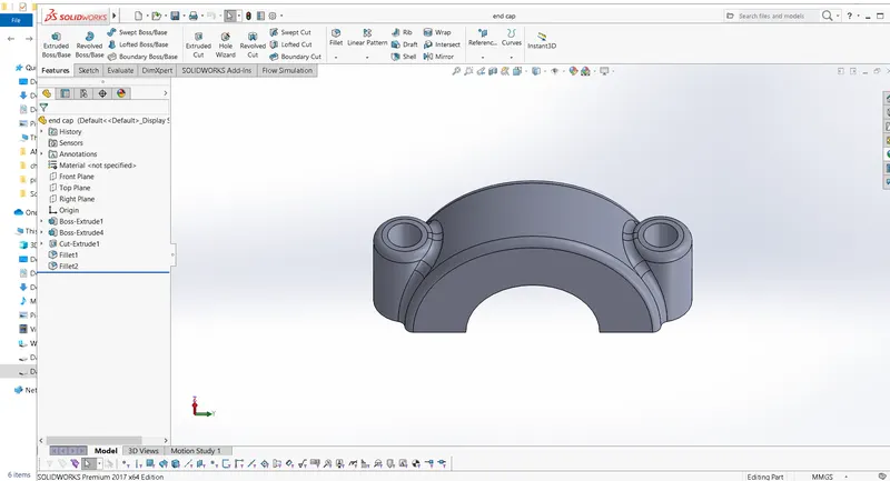
An end cap is the removable section of a two-piece connecting rod that provides a bearing surface for a crankpin journal.
Connecting rod
cap end
crank
A crank is an arm attached at a right angle to a rotating shaft by which circular motion is imparted from the shaft. in a reciprocating engine, it translates reciprocating motion into rotational motion.
crank is a rotating part of the piston assembly.
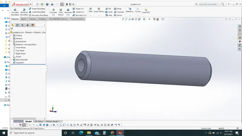
Gudgeon Pin (Wrist Pin)
In an IC engine, the gudgeon pin connects the piston to the connecting rod. provides bearing for the connecting rod to pivot upon as the piston moves.
STEP 2:- assembly Of Part
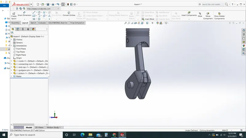
The following mates are used for piston assembly.
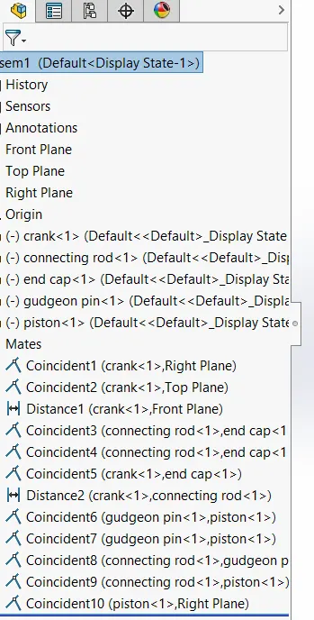
STEP 3:- Simulation of Piston assembly
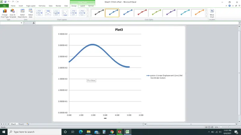
linear Displacement with '0'mm Offset
after simulation with given constraint, the result we get is, with '0' mm offset linear displacement is 303.15mm.
linear Displacement with '+10' mm offset
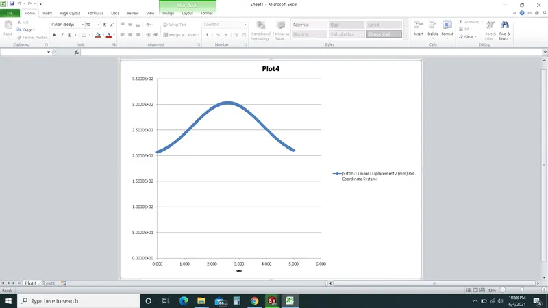
linear displacement with '-10' mm offset
Then Required result for linear displacement for both the offset('+10'&'-10') is the same i.e 303.16mm.
Then after all superimposition of data takes place for 3 cases
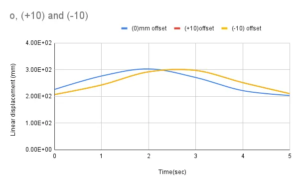
from the above information, we observed that result obtained is the same303mm.
conclusion:-
1)from above these all 3 cases are observed that result we got for linear displacement 303mm near by same.
2) generally we observed that bigger engine displacement developed more torque, but small engine spin faster with maximum horsepower output .
3)To given offset cylinder axis & crankshaft axis minimize rod angularity when cylinder pressure at its highest .reduce angularity leads to lower piston thrust force, hence lower frictional losses.
NOTE:- changes in input, the parameter of crank speed take due to some technicality issues that occur while a simulation.
actual rpm - 2000rpm & change -10rpm .