Gate Valve Parametric Study
Aim :
To Perform Parametric study on the gate valve
Introduction :
A gate valve, also known as a sluice valve, is a valve that opens by lifting a barrier (gate) out of the path of the fluid. Gate valves require very little space along the pipe axis and hardly restrict the flow of fluid when the gate is fully opened.
Theory :
Gate valves are used to shut off the flow of liquids rather than for flow regulation. When fully open, the typical gate valve has no obstruction in the flow path, resulting in very low flow resistance. The size of the open flow path generally varies in a nonlinear manner as the gate is moved. This means that the flow rate does not change evenly with stem travel. Depending on the construction, a partially open gate can vibrate from the fluid flow.
Gate valves are mostly used with larger pipe diameters since they are less complex to construct than other types of valves in large sizes.At high pressures, friction can become a problem. As the gate is pushed against its guiding rail by the pressure of the medium, it becomes harder to operate the valve. Large gate valves are sometimes fitted with a bypass controlled by a smaller valve to be able to reduce the pressure before operating the gate valve itself.
In this study we are going to move the Gate-Disk and will calculate mass flow rate for it .
Solving & Modelling approach
Governing Equation
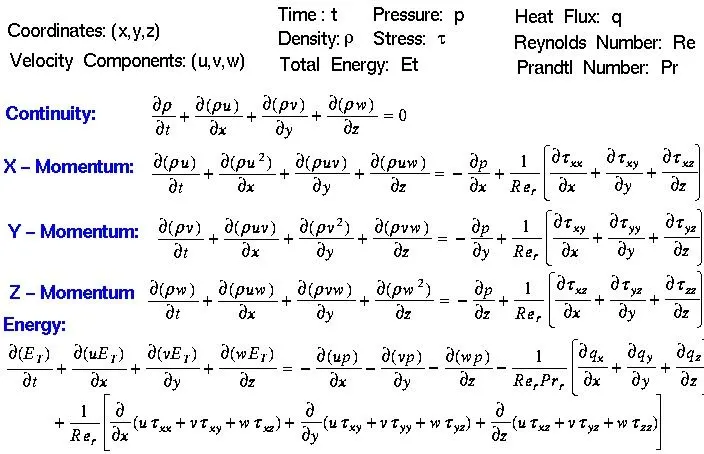
`K_v = Q*sqrt((SG)/(triangleP)` - Flow Factor
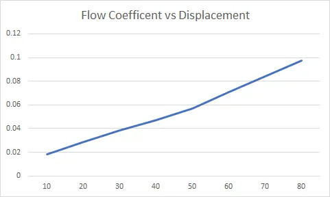
`C_v = (K_v)/(0.865)` - Flow Coefficient
Pre-processing and solver setting
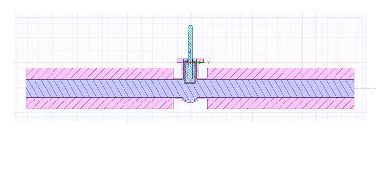
Geometry :
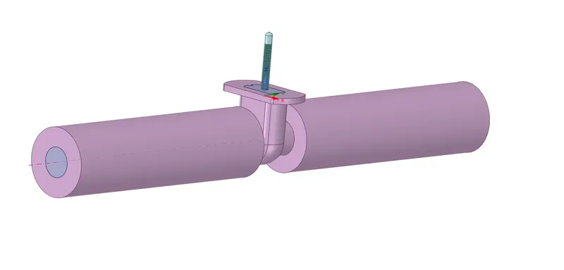
Gate Disk Lift = 0.01 m
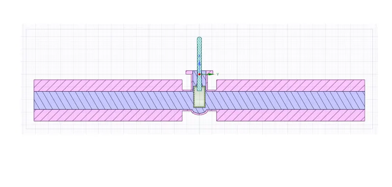
Gate Disk Lift = 0.02
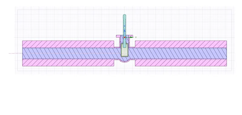
Gate Disk Lift = 0.03
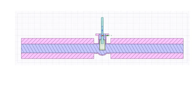
Gate Disk Lift = 0.04
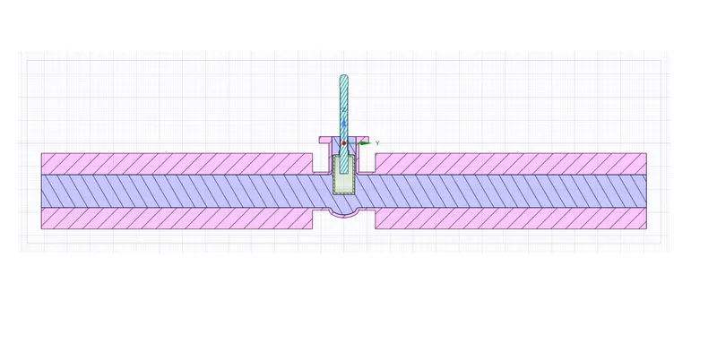
Gate Disk Lift = 0.05
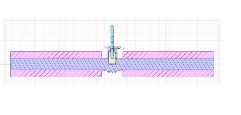
Gate Disk Lift = 0.06
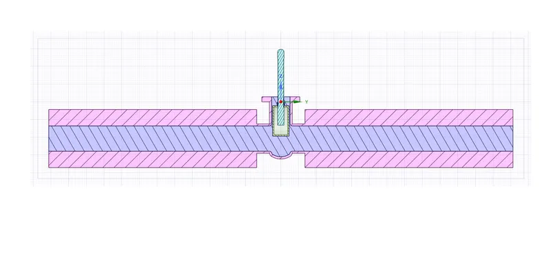
Gate Disk Lift = 0.07
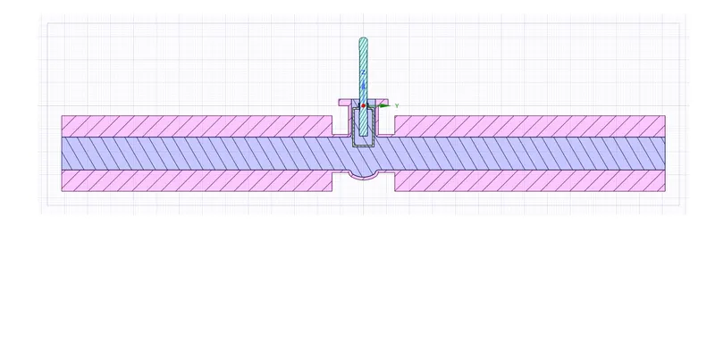
Gate Disk Lift = 0.08
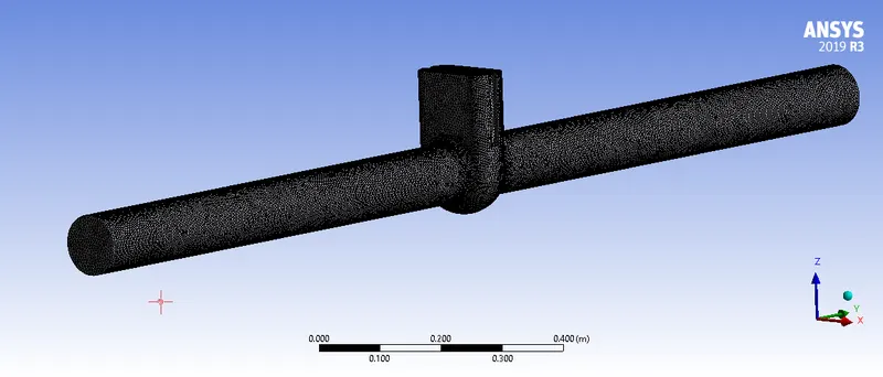
Mesh
Boundaries
Inlet :
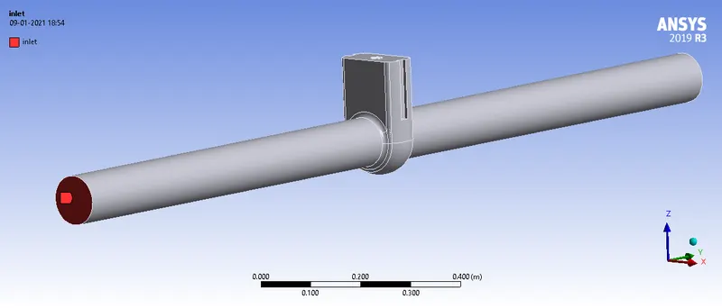
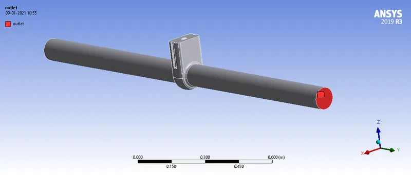
Outlet :
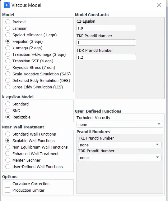
Viscous Model
Results :
Residuals
Gate disk lift = 0.01 m
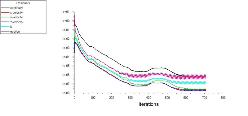
Gate disk lift = 0.02 m
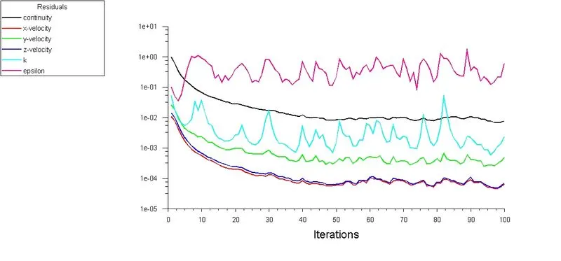
Gate disk lift = 0.03 m
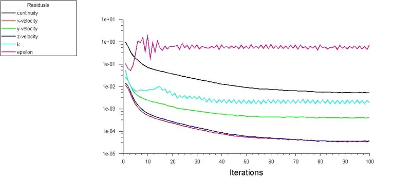
Gate disk lift = 0.04 m
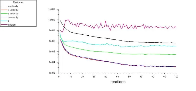
Gate disk lift = 0.05 m
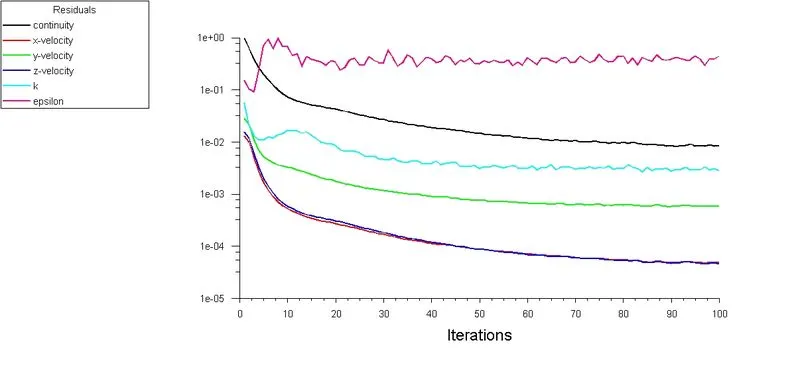
Gate disk lift = 0.06 m
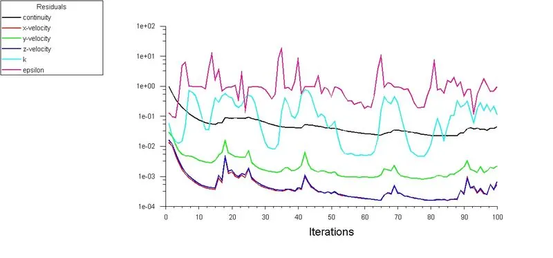
Gate disk lift = 0.07 m
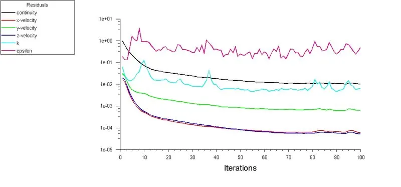
Gate disk lift = 0.08 m
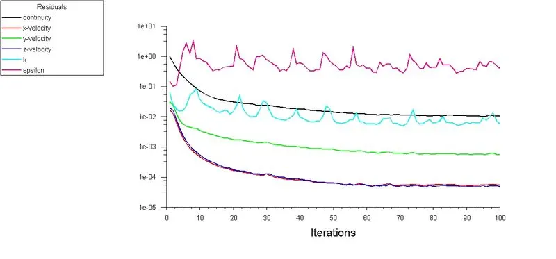
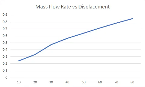
Mass Flow Rate
Gate disk lift = 0.01 m
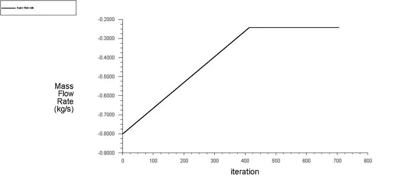
Gate disk lift = 0.02 m
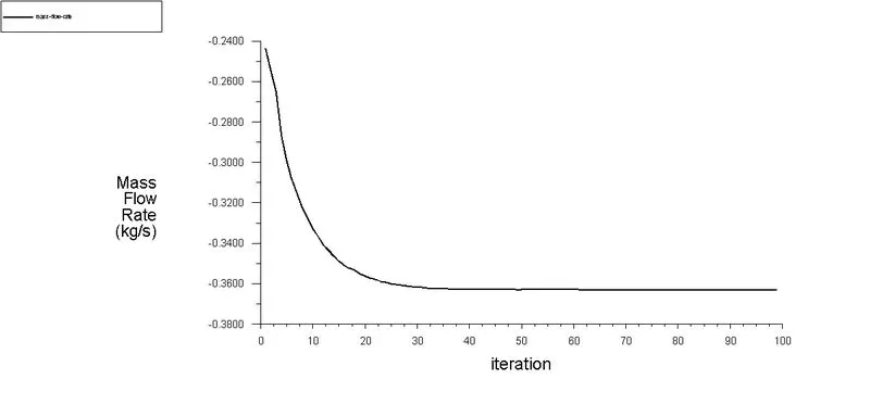
Gate disk lift = 0.03 m
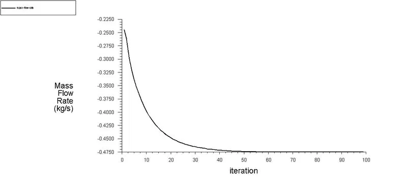
Gate disk lift = 0.04 m
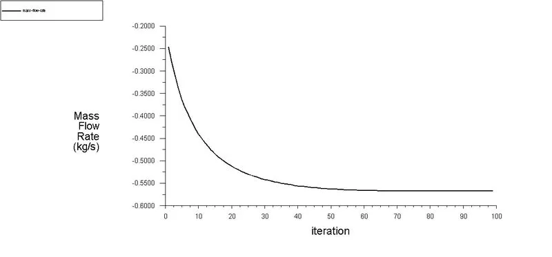
Gate disk lift = 0.05 m
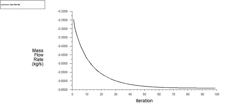
Gate disk lift = 0.06 m
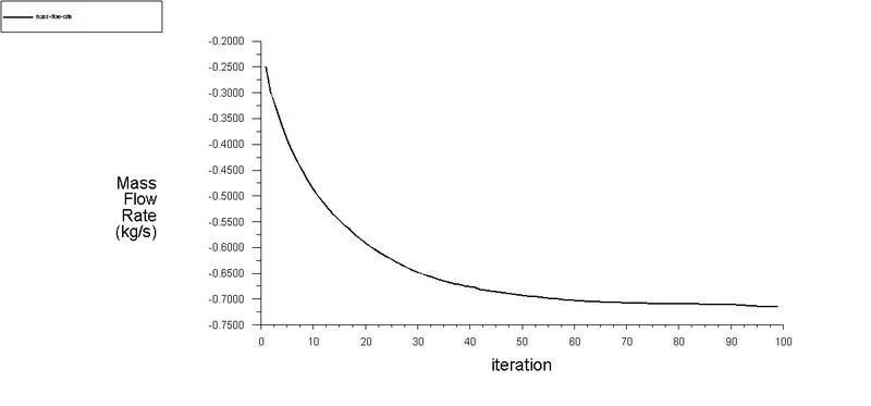
Gate disk lift = 0.07 m
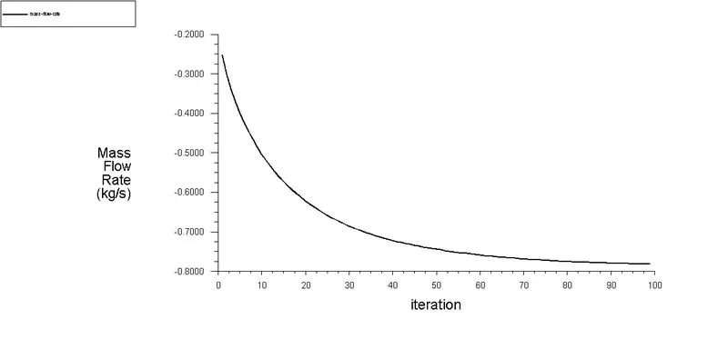
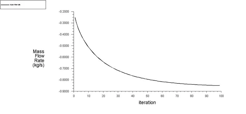
Gate disk lift = 0.08 m
Table
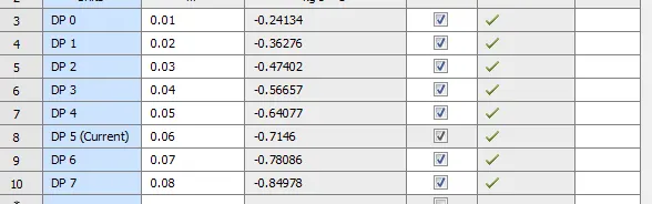
Mass Flow outlet Pressure Drop Flow Factor Flow Coefficient

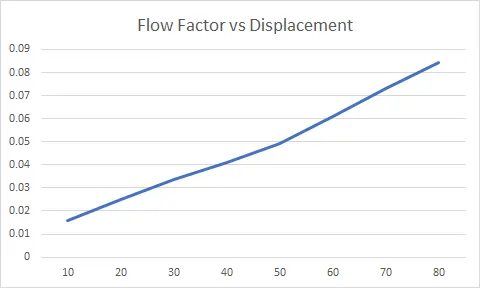
Conclusions :
- It was observed that Mass Flow rate, Flow coefficient, Flow Factor increases on increasing the Disk Displacement