Cyclone Separator Challenge
Aim:- To perform analysis on cyclone separator and calculate the separation efficiency and pressure drop.
Introduction :
A cyclone separator is a device for removing particulates from an air, gas, or liquid stream, without the use of filters, through vortex separation. When removing particulate matter from liquid, a hydro-cyclone is used; while from gas, a gas cyclone is used. Rotational effects and gravity are used to separate mixtures of solids and fluids. The cyclone separator can also be used to separate fine droplets of liquid from a gaseous stream.
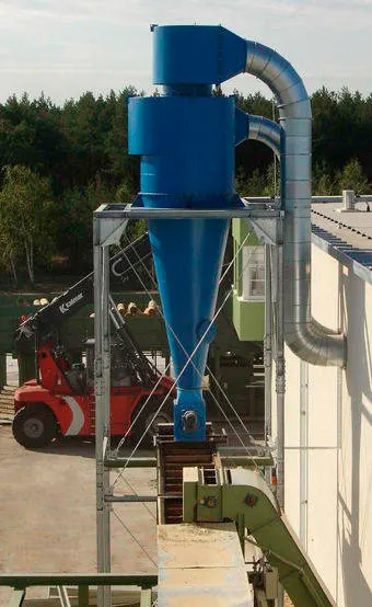
A real-world separator
Theory :
Working
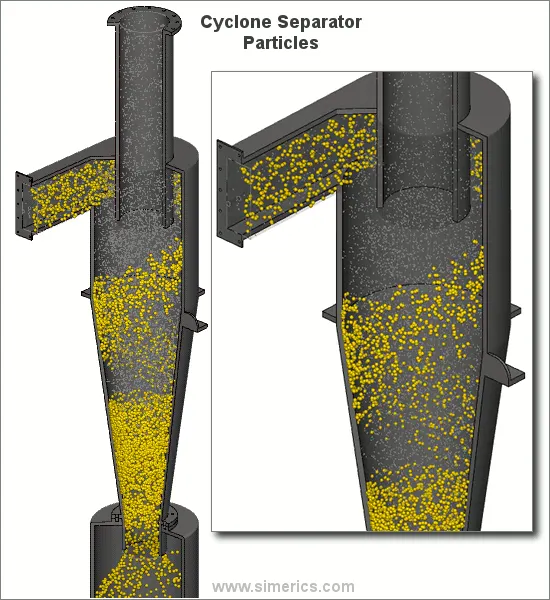
Cyclone separators work much like a centrifuge, but with a continuous feed of dirty air. In a cyclone separator, dirty flue gas is fed into a chamber. The inside of the chamber creates a spiral vortex, similar to a tornado. The lighter components of this gas have less inertia, so it is easier for them to be influenced by the vortex and travel up it. Contrarily, larger components of particulate matter have more inertia and are not as easily influenced by the vortex. Since these larger particles have difficulty following the high-speed spiral motion of the gas and the vortex, the particles hit the inside walls of the container and drop down into a collection hopper. These chambers are shaped like an upside-down cone to promote the collection of these particles at the bottom of the container. The cleaned flue gas escapes out the top of the chamber. Most cyclones are built to control and remove particulate matter that is larger than 10 micrometers in diameter. However, there do exist high-efficiency cyclones that are designed to be effective on particles as small as 2.5 micrometers. As well, these separators are not effective on extremely large particulate matter. For particulates around 200 micrometers in size, gravity settling chambers or momentum separators are a better option.
Effectiveness
Cyclone separators are generally able to remove somewhere between 50-99% of all particulate matter in the flue gas. How well the cyclone separators are actually able to remove this matter depends largely on particle size. If there is a large amount of lighter particulate matter, less of these par0ticles are able to be separated out. Because of this, cyclone separators work best on flue gases that contain large amounts of big particulate matter.
Empirical models used to calculate the cyclone separator efficiency
1. Iozia and Leith Model
Iozia and Leith's logistic model is a modified version of the Barth Model, which is developed based on force balance. The model assumes that a particle carried by the vortex endures the influence of two forces: a centrifugal force, Z, and flow resistance, W. The collection efficiency `eta_(i)` of particle diameter `d_(p i)`can be calculated from
`eta_(i) = 1/(1 + (d_(p c)/d_(p i))^(beta)`
`beta` is an expression for slope parameter derived based on the statistical analysis of experimental data of a cyclone with D = 0.25 m given as
`beta = 0.62 - 0.87*ln(d_(pc)/100) + 5.21*ln((ab)/D^2) + 1.05*(ln((ab)/D^2) )^2`
and `d_(pc)` is the 50% cut size given by Barth
`d_(pc) = [(9*mu*Q)/(pi*rho_(p)*z_(c)*(v_(t max)^2))]^0.5`
where core length, zc, and core diameter, dc, are given as
`z_c = (H-S) - [(H - S)/((D/B - 1))][(d_c/B) - 1]`
`z_c = (H-S ) if d_c`
`d_c = 0.47*D*((ab)/D^2)^(-0.25) *(D_e/D)^1.4`
2. Li and Wang Model
The Li and Wang model include particle bounce or re-entrainment and turbulent diffusion at the cyclone wall. A two-dimensional analytical expression of particle distribution in the cyclone is obtained. Li and Wang's model was developed based on the following assumptions:
I . The radial particle velocity and the radial concentration profile are not constant for uncollected particles within the cyclone.
II . Boundary conditions with the consideration of turbulent diffusion coefficient and particle bounce re-entrainment on the cyclone wall are :
`c = c_o`
`D_r*((delc)/(delr)) = (1 - alpha)*w*c`
`c(r,theta) = (c_0(r_w-r_n)*exp{-lamda*[(1/(K.(1+n)))*r^(1+n)]})/(int_(r_n)^(r_w)*exp{(1/(K*(1+n))*r^(n+1))}`
`K = ((1-n)*(rho_p-rho_g)*d^2*Q)/(18*mu*b*(r_w^(1-n) - r_n^(1-n))`
3. Koch and Licht Model
Koch and Licht's collection theory recognized the inherently turbulent nature of cyclones and the distribution of gas residence times within the cyclone. Koch and Licht described particle motion in the entry and collection regions with the additional following assumptions:
I. The tangential velocity of a particle is equal to the tangential velocity of the gas flow, i.e. there is no slip in the tangential direction between the particle and the gas.
II. The tangential velocity is related to the radius of the cyclone by `u.R^n` = constant.
`G = (8*K_c)/(K_a^2*K_b^2)`
`eta = 1 - {1 - (12*D)^0.4/(2.5)}*{(T+460)/530}^0.3`
`tau_i = (rho_p*d_(p i)^2)/(18*mu)`
4. Koch Model
Lapple model was developed based on force balance with out considering the flow resistance. Lapple assumed that a partcle entering the cyclone is evenly distributed across the inlet
opening. The particle that travels from inlet half width to the wall in the cyclone is collected with 50% efficiency. The semi empirical relationship developed by Lapple [1] to calculate a
50% cut diameter, `d_(pc)`, is
`d_(pc) = [(9*mub)/(2*pi*nu_(i)*(rho_p-rho_g))]^(1/2)`
`N_e = 1/a*[h + (H-h)/2]`
`eta_i = 1/(1 + (d_(p c)/d_(p i))^2`
Solving & Modelling approach
There are two objectives here:
- Solve for the particle size of 1 and 5 micrometers with 3 metre per second
- Solve for 1,3,5 metre per second for particle diameter of 5 micrometers
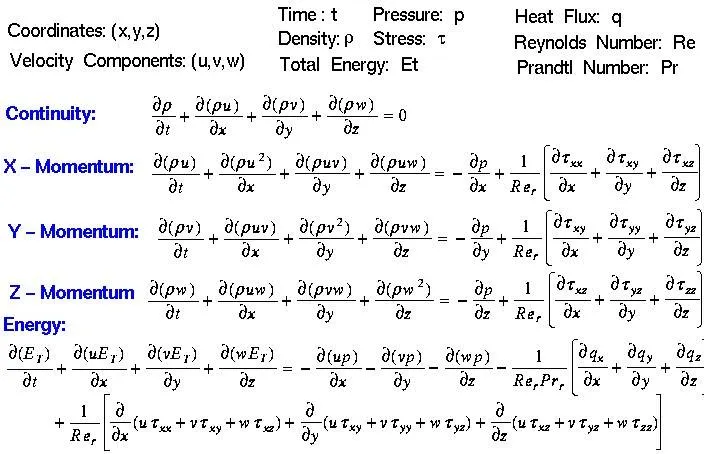
Governing Equations :
Pre-processing and solver setting
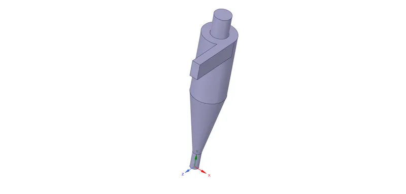
Geometry
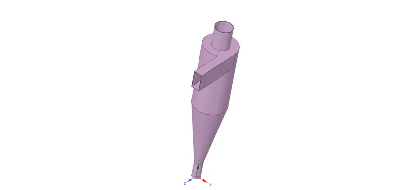
Geometry - extracted volume
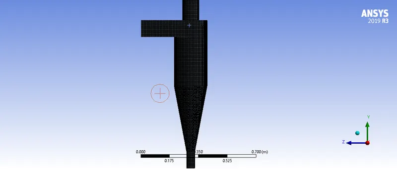
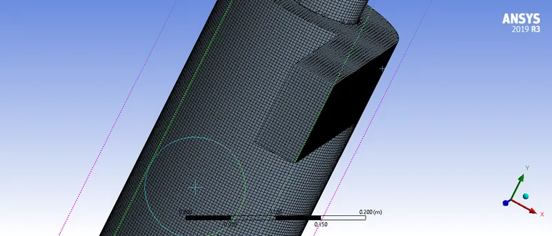
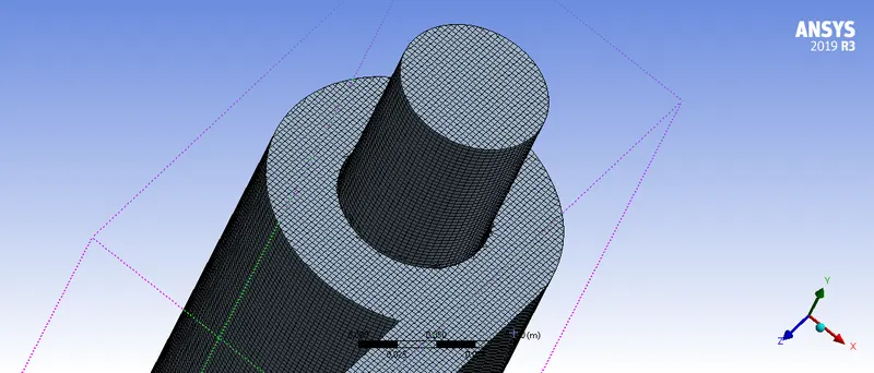
Mesh
Assembly Meshing Method - Cut cell
Element size - 5 mm
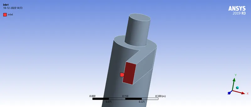
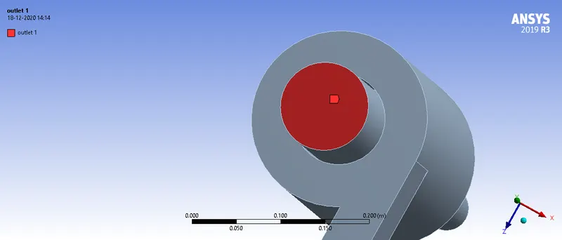
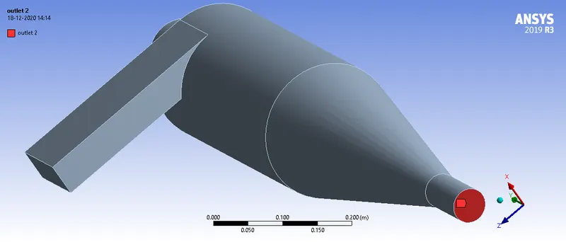
Boundaries
Inlet
Outlet 1
Outlet 2
Solver
Gravity was turned on this case and a Pressure based solver was used
Viscous Model :
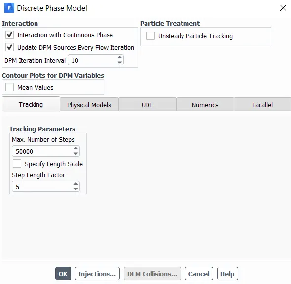
Discrete Phase Model:
Initialization :
Standard - compute from the inlet
Results
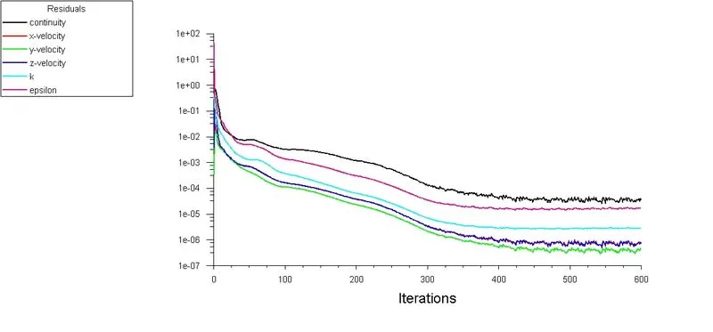
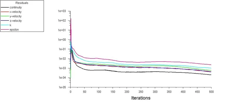
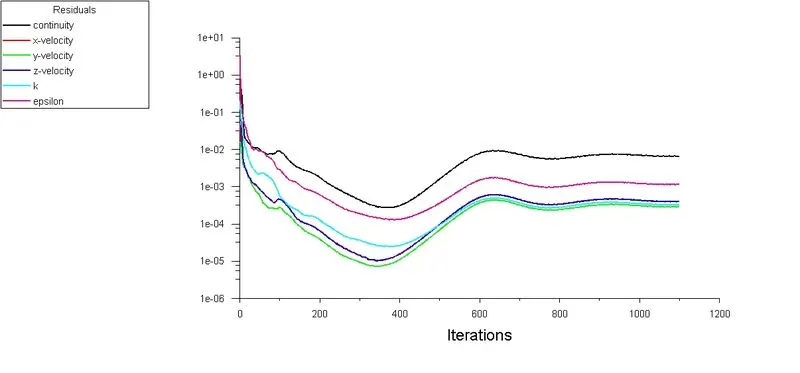
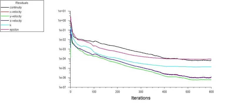
Residuals
For velocities 1,3,5 `ms^-1` for diameter 5`mu`m
1 `ms^-1`
3`ms^-1`
5`ms^-1`
For particle size 1`mu`m and 5 `mu` m for velocity 3`ms^-1`
For 1`mu` m
For 5 `mu`m
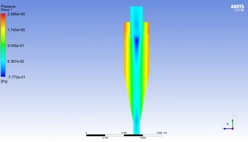
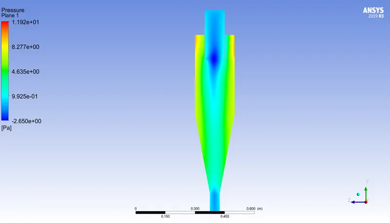
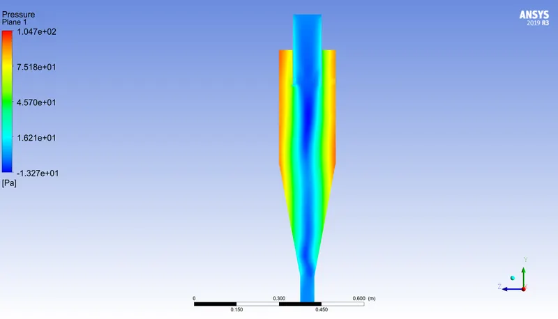
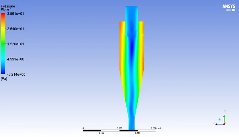
Pressure Drop
| S.No | Particle Size `mu`m | Velocity `ms^-1` | Gauge Pressure at (inlet) | Gauge Pressure at (outlet-2) | Drop |
| 1 | 5 | 1 |
2.5324959 |
0 |
2.5324959 |
| 2 | 5 | 3 |
10.847379 |
0 |
10.847379 |
| 3 | 5 | 5 |
100.05865 |
0 |
100.05865 |
| 4 | 1 | 3 |
34.123147 |
0 |
34.123147 |
| 5 | 3 | 3 |
34.123147 |
0 |
34.123147 |
Separator efficiency
| S.No | Particle Size `mu`m | Velocity `ms^-1` | Trapped particle | Tracked | Incomplete Particle | Efficiency |
| 1 | 5 | 1 | 9 | 465 | 363 | 8.82 |
| 2 | 5 | 3 | 322 | 465 | 0 | 69.2 |
| 3 | 5 | 5 | 1 | 465 | 456 | 11.1 |
| 4 | 1 | 3 | 5 | 465 | 317 | 3.37 |
| 5 | 5 | 3 | 0 | 465 | 462 | 0 |
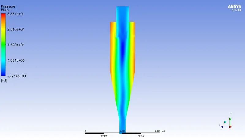
Pressure Contour
Velocity - 1 `ms^-1` , Particle Diameter - 5`mu`m
Velocity - 3 `ms^-1` , Particle Diameter - 5`mu`m
Velocity - 5 `ms^-1` , Particle Diameter - 5`mu`m
Velocity - 3 `ms^-1` , Particle Diameter - 1`mu`m
Velocity - 3`ms^-1` , Particle Diameter - 5`mu`m
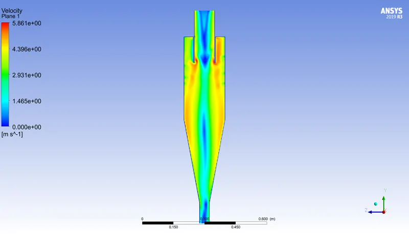
Velocity Counotur
Velocity - 1 `ms^-1` , Particle Diameter - 5`mu`m
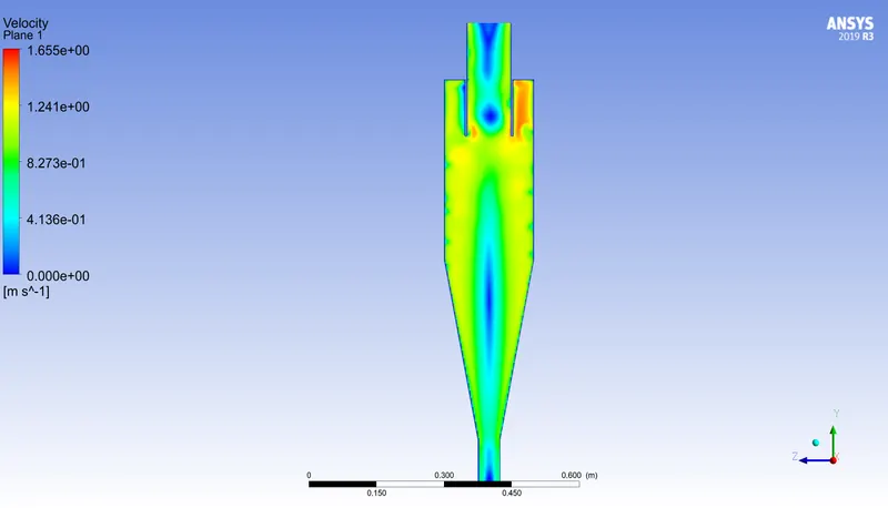
Velocity - 3 `ms^-1` , Particle Diameter - 5`mu`m
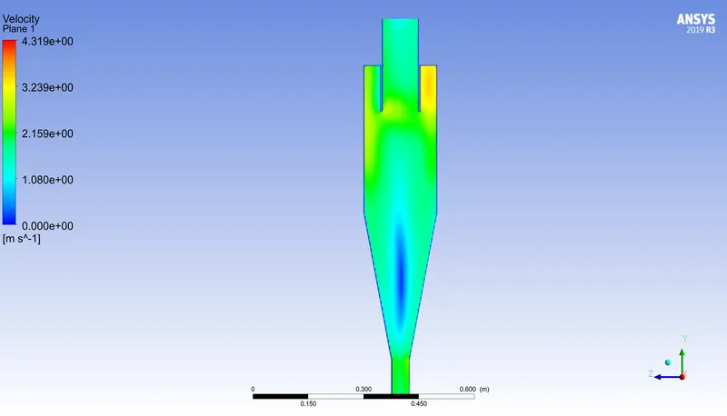
Velocity - 5 `ms^-1` , Particle Diameter - 5`mu`m
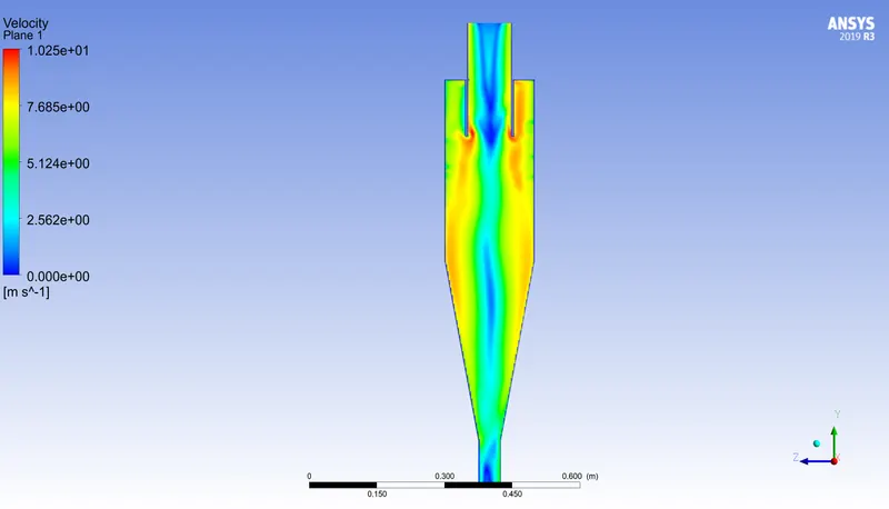
Velocity - 3 `ms^-1` , Particle Diameter - 1`mu`m
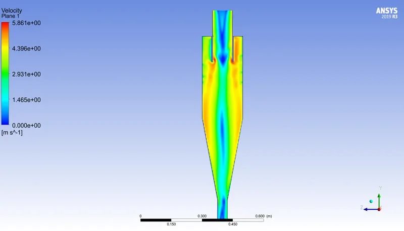
Velocity - 3`ms^-1` , Particle Diameter - 5`mu`m
Vortex
Velocity - 1 `ms^-1` , Particle Diameter - 5`mu`m
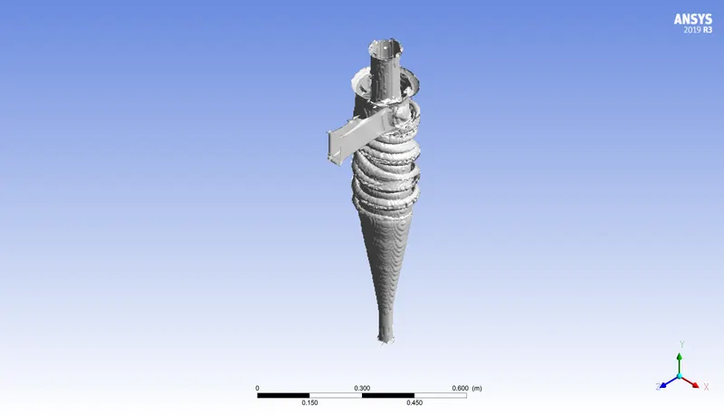
Velocity - 3 `ms^-1` , Particle Diameter - 5`mu`m
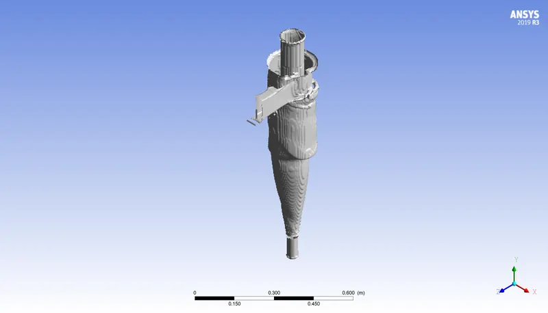
Velocity - 5 `ms^-1` , Particle Diameter - 5`mu`m
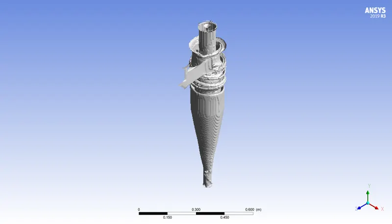
Velocity - 3 `ms^-1` , Particle Diameter - 1`mu`m
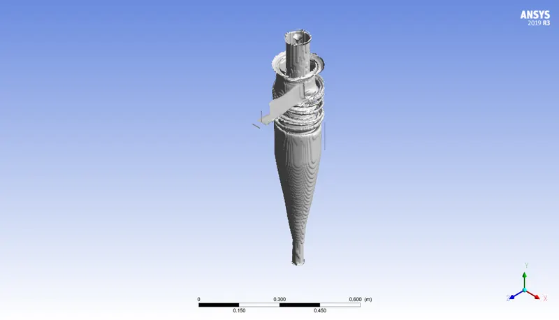
Velocity - 3 `ms^-1` , Particle Diameter - 5`mu`m
Particle Time
Velocity - 1 `ms^-1` , Particle Diameter - 5`mu`m
Velocity - 3 `ms^-1` , Particle Diameter - 5`mu`m
Velocity - 5 `ms^-1` , Particle Diameter - 5`mu`m
Velocity - 3 `ms^-1` , Particle Diameter - 1`mu`m
Velocity - 3 `ms^-1` , Particle Diameter - 5`mu`m
Conclusion
- It can be seen that the particle size has no effect on pressure drop and but pressure drop increases on an increase in particle velocity
- Efficiency has a very random effect on it with velocity and particle size variation