Exhaust Port Challenge
Aim :
To perform CHT analysis on exhaust port using ANSYS-FLUENT
Introduction :
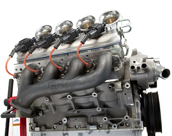
An exhaust system is usually piping used to guide reaction exhaust gases away from a controlled combustion inside an engine or stove. The entire system conveys burnt gases from the engine and includes one or more exhaust pipes. In this project was simulation was performed on two meshes. First with automatically generated mesh and other with the refined mesh while maintaining y+.
Theory :
The contemporary conjugate convective heat transfer model was developed after computers came into wide use in order to substitute the empirical relation of proportionality of heat flux to temperature difference with heat transfer coefficient which was the only tool in theoretical heat convection since the times of Newton. This model, based on a strictly mathematically stated problem, describes the heat transfer between a body and a fluid flowing over or inside it as a result of the interaction of two objects. The physical processes and solutions of the governing equations are considered separately for each object in two subdomains. Matching conditions for these solutions at the interface provide the distributions of temperature and heat flux along the body–flow interface, eliminating the need for a heat transfer coefficient.
One simple way to realize conjugation is to apply the iterations. The idea of this approach is that each solution for the body or for the fluid produces a boundary condition for other components of the system. The process starts by assuming that one of the conjugate conditions exists on the interface. Then, one solves the problem for the body or for fluid applying the guessing boundary condition and uses the result as a boundary condition for solving a set of equations for another component, and so on. If this process converges, the desired accuracy may be achieved. However, the rate of convergence highly depends on the first guessing condition, and there is no way to find a proper one, except through trial and error.
Solving & Modelling approach :
Simulations were performed using commercial CFD software ANSYS - FLUENT
Mach Number :
`Mach = 5/492 = 0.01016`
which is less than 0.3 hence it is the case of incompressible solver
Governing Equation :
Navier - Stokes
`rho*(DV)/(Dt) = -nabla*p + rho*g + mu*nabla^2*V`
Continuity
`nabla*vecV = 0`
Convection Equation
`dq = h*dT`
Pre-processing and solver setting :
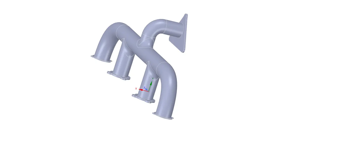
Geometry :
Meshing :
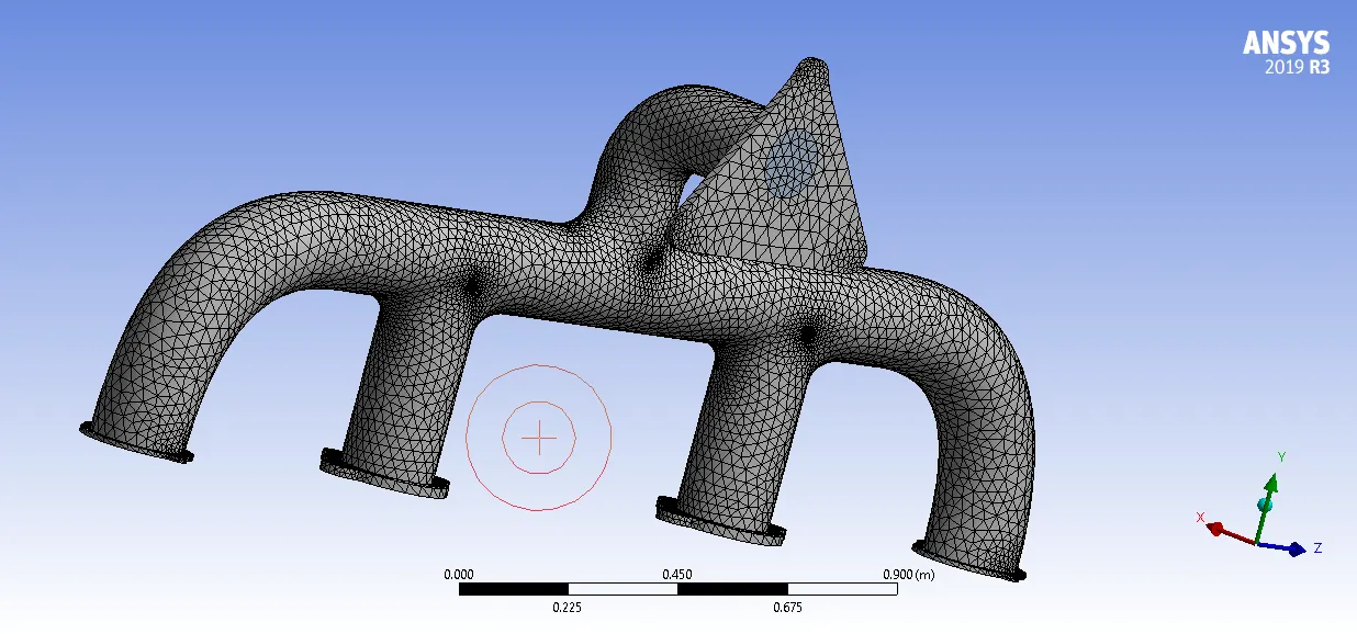
Non Refined :
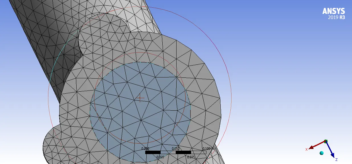
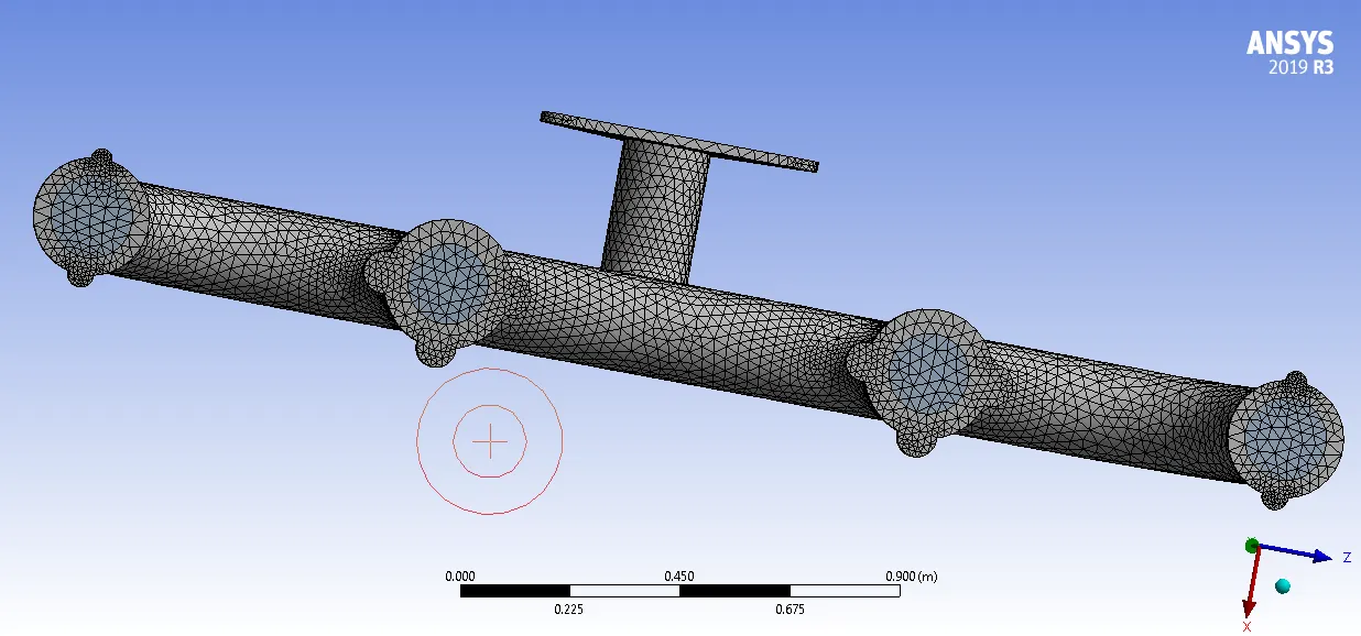
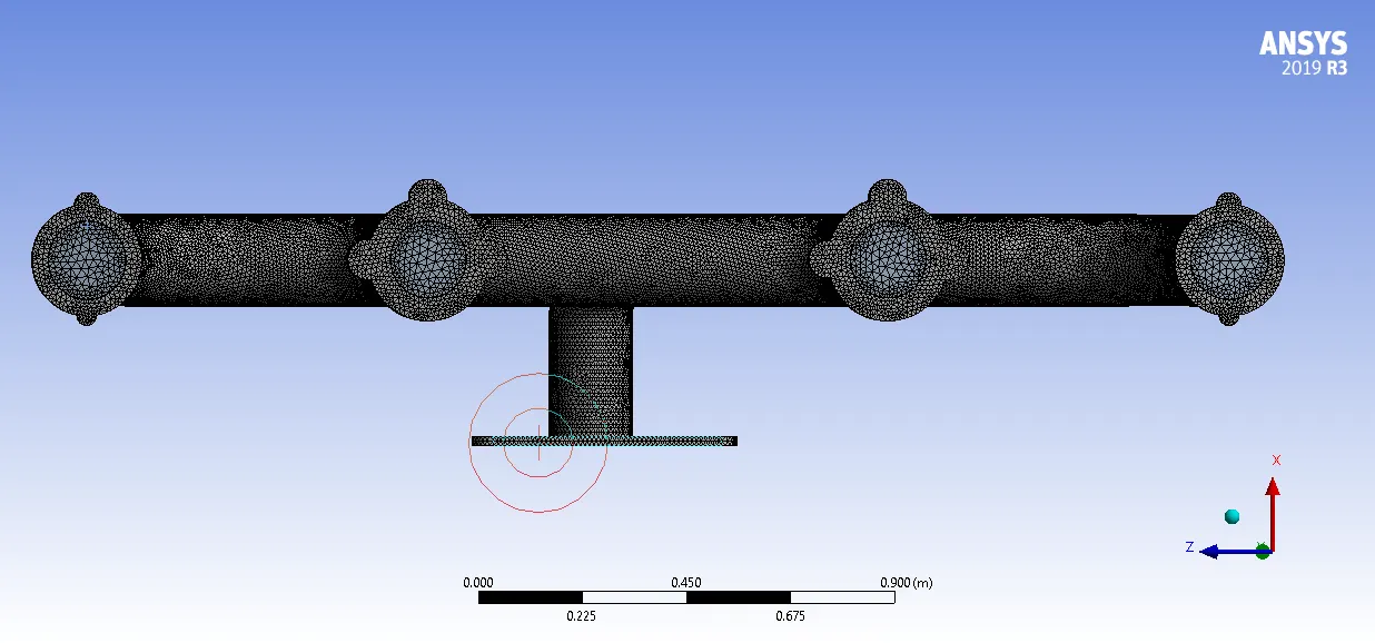
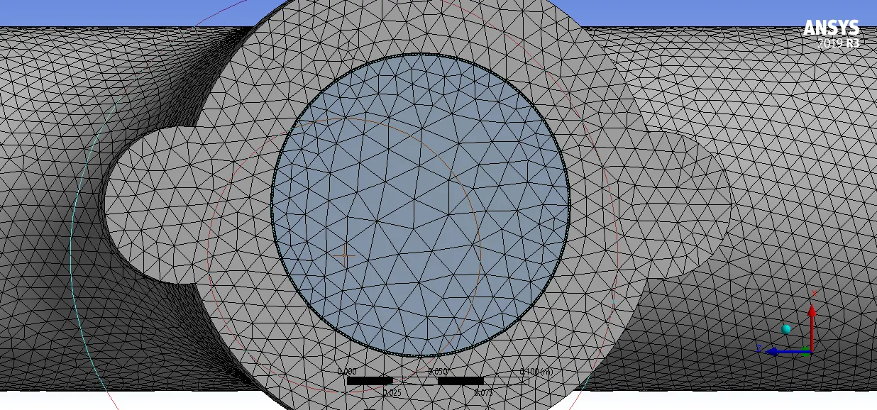
Refined :
Element size = 0.01 m
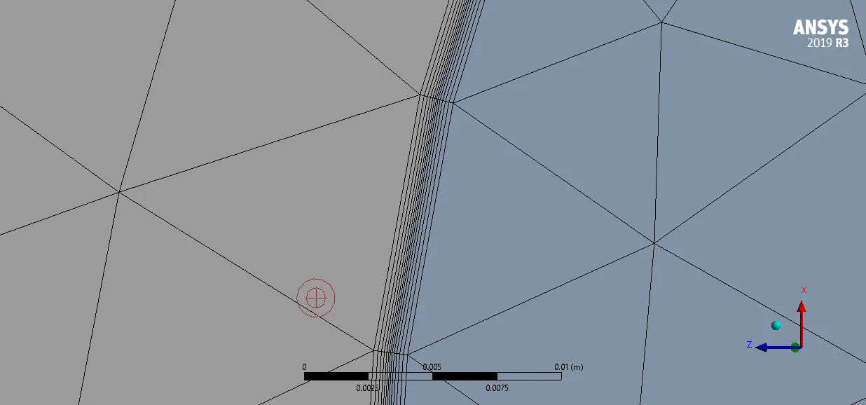
Inflation layer at inlet :
Boundaries :
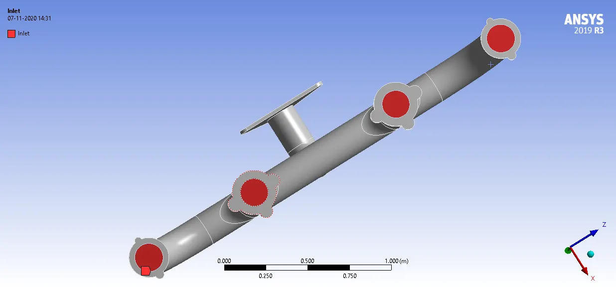
INLET
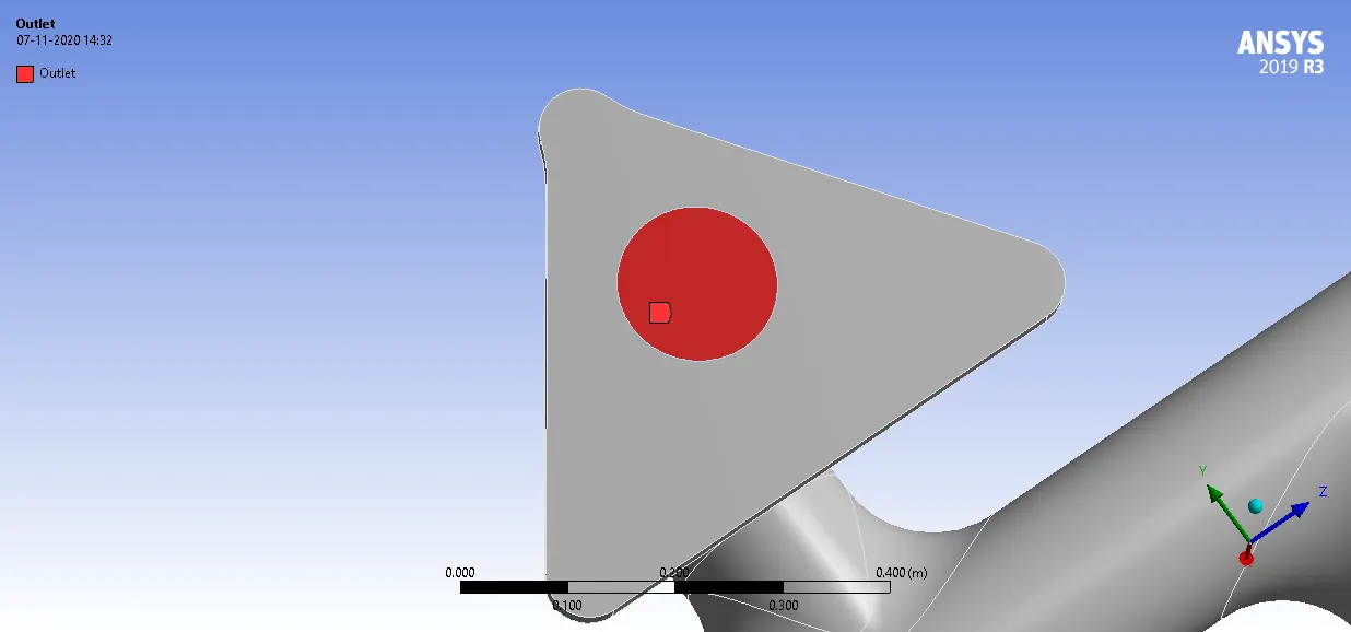
OUTLET
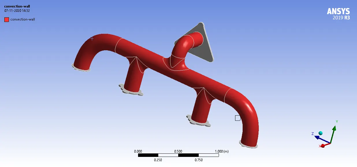
CONVECTION WALL
Boundary Conditions :
| Inlet | 5 m/s |
| Outlet | Pressure Outlet - Gauge = 0 |
| Convection wall | h = 20 W/m-K |
SOLVER :
The energy equation was turned on
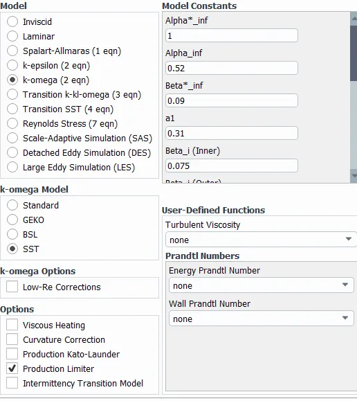
Turbulence Model :
Results :
Unrefined :
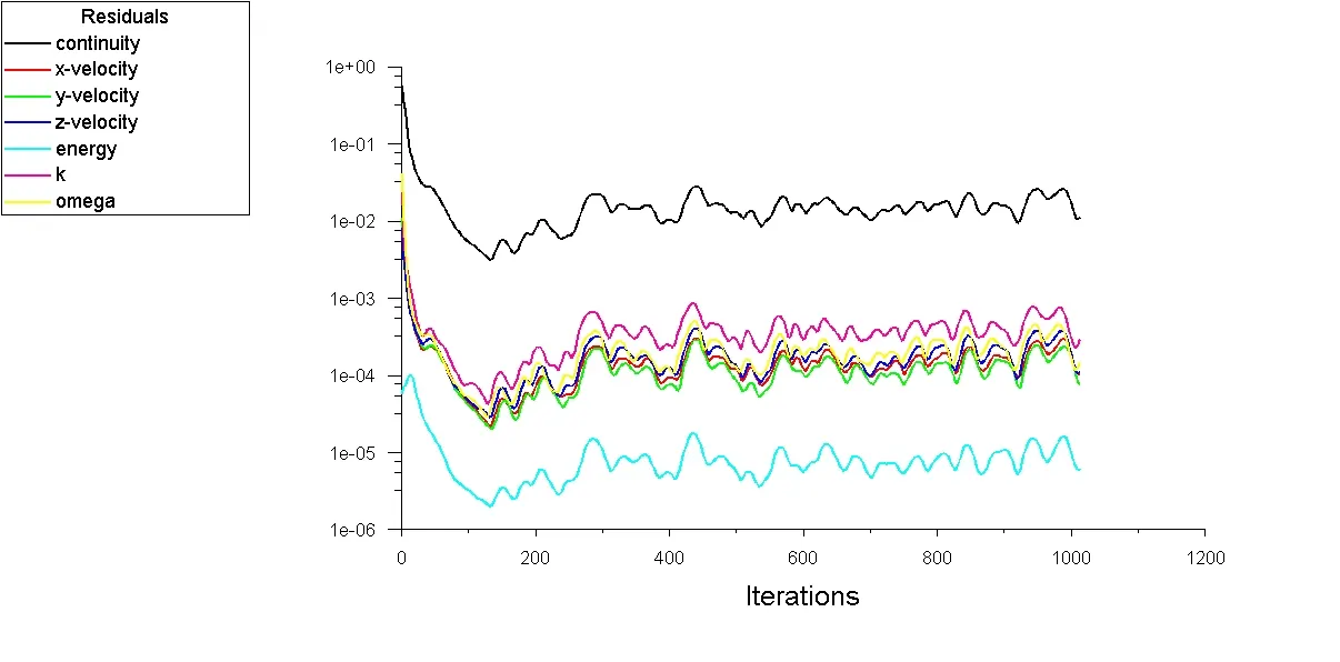
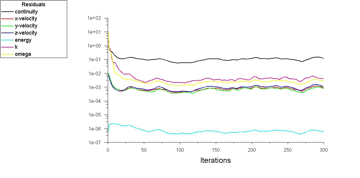
Residuals
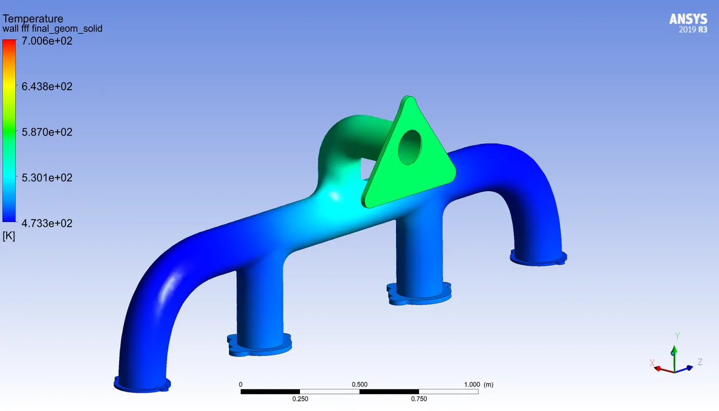
Temperature Distribution on the wall :
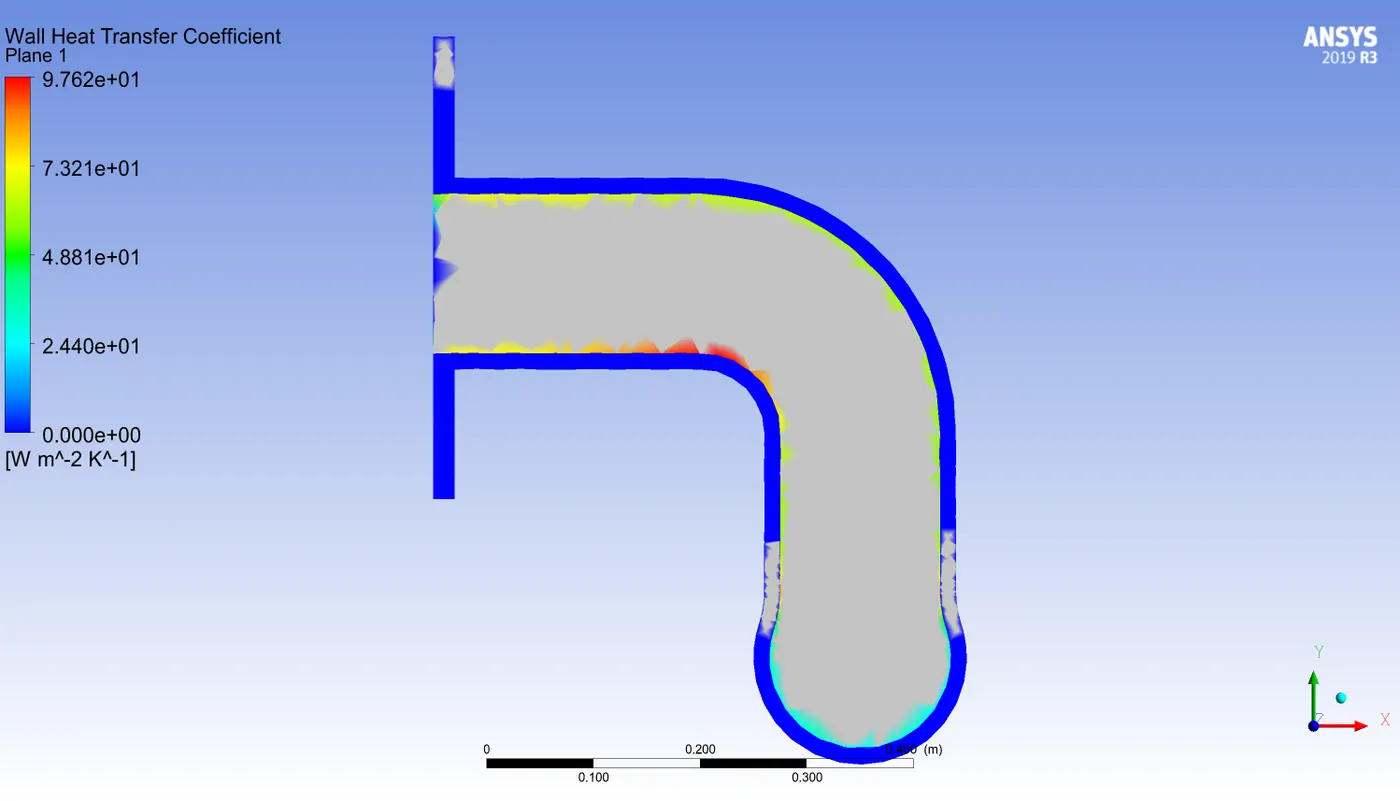
heat transfer coefficient :
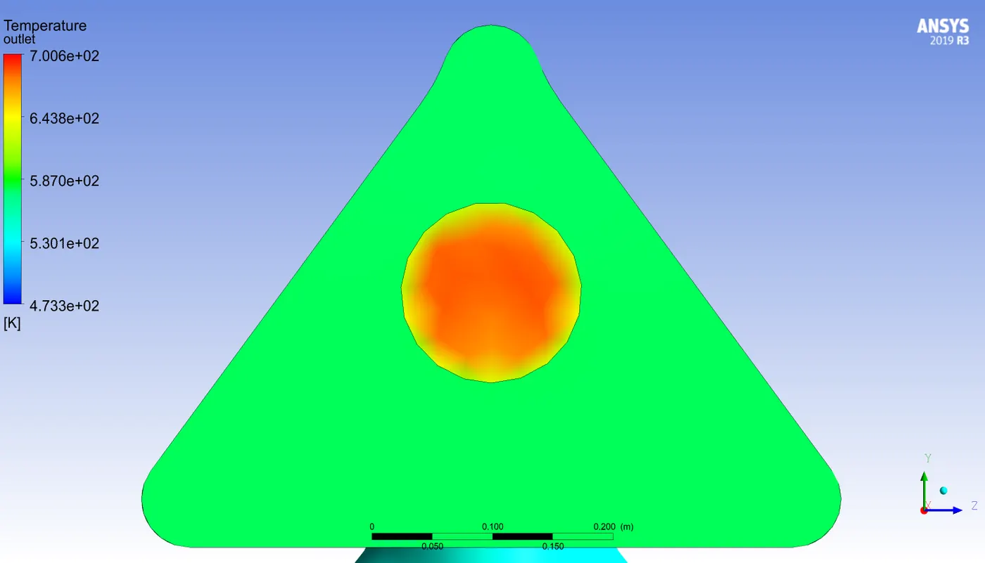
outlet temperature variation:
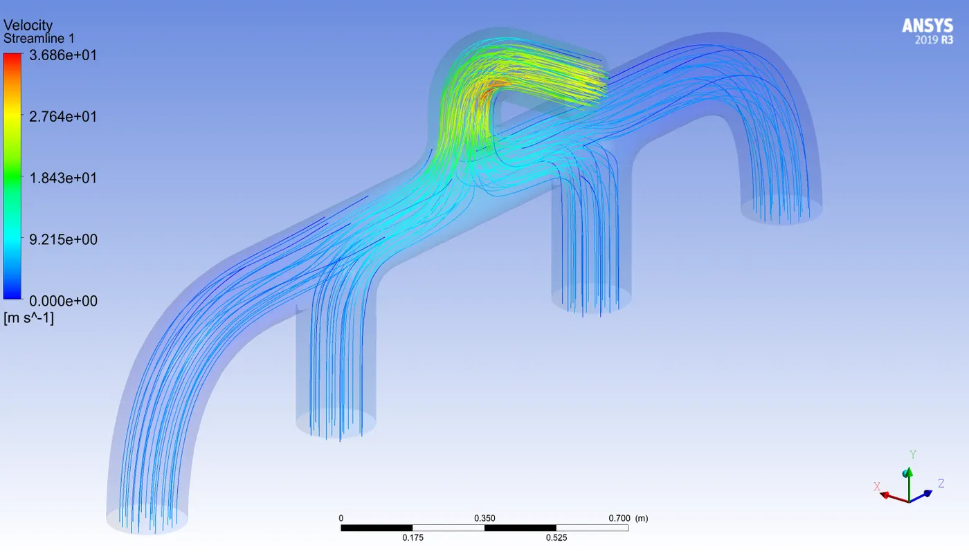
Streamlines :
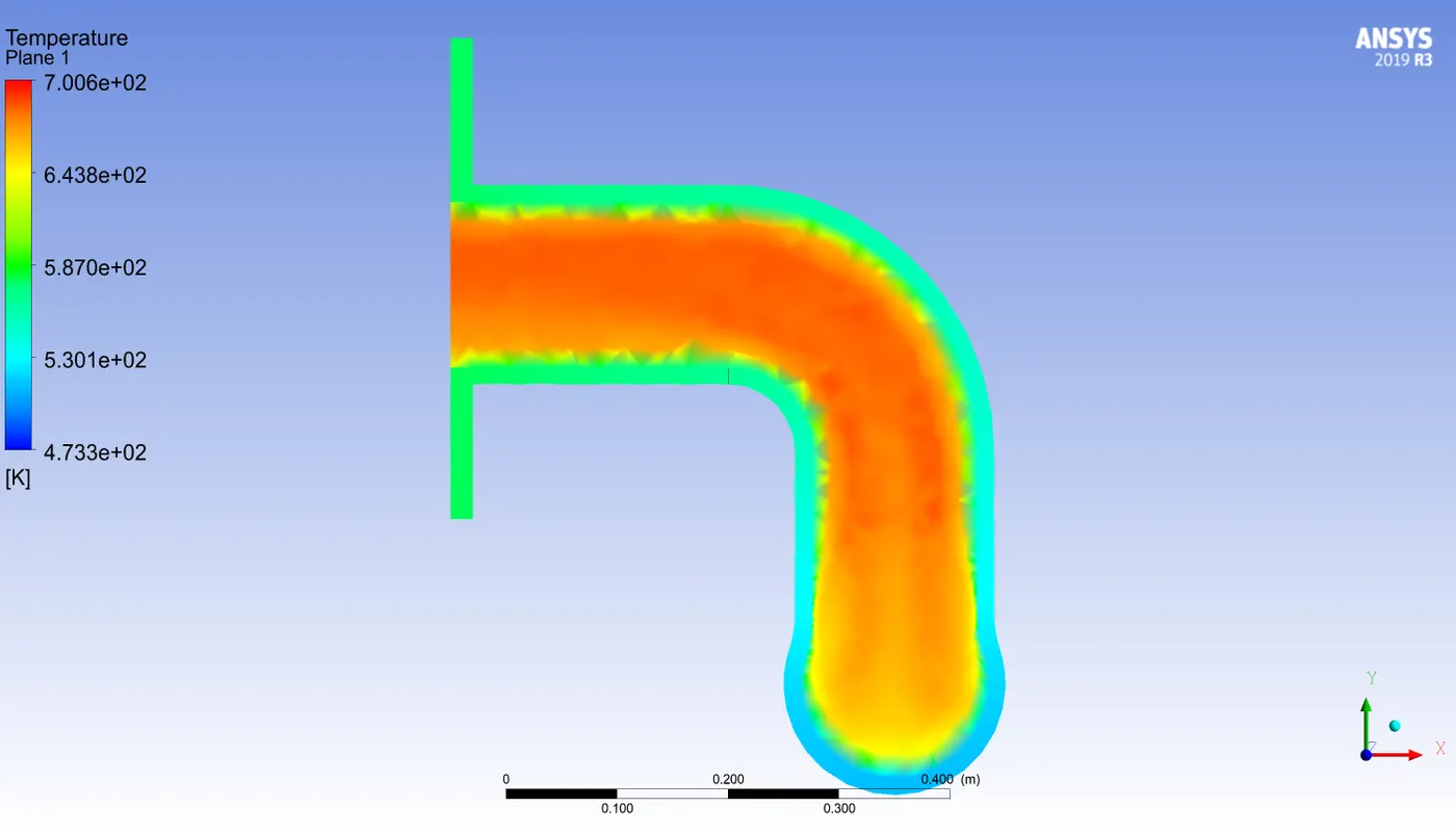
temperature variation on the plane :
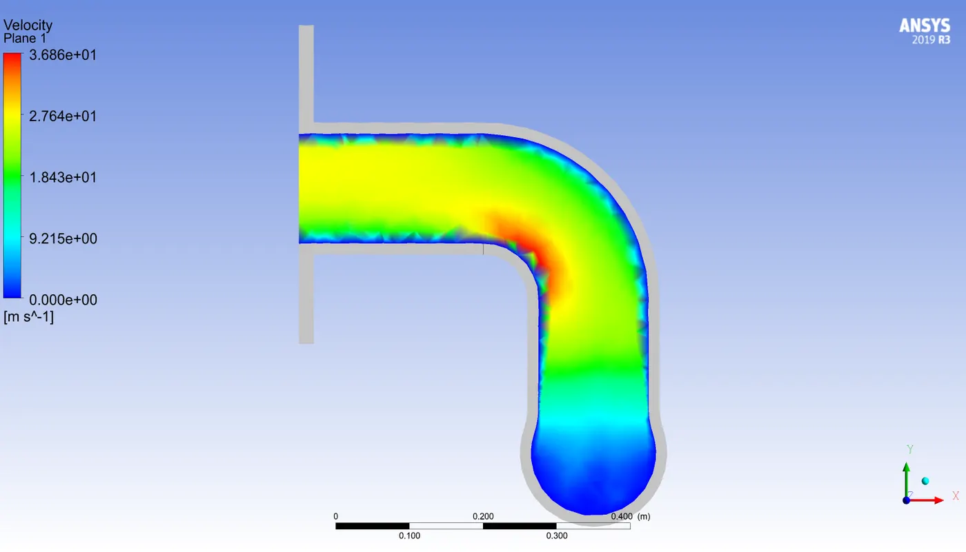
Velocity variation on the plane :
Refined :
Residuals :
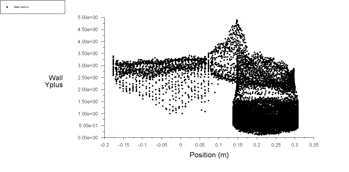
Y+ value maintained between 0 - 5 (which is desirable for k-omega SST) :
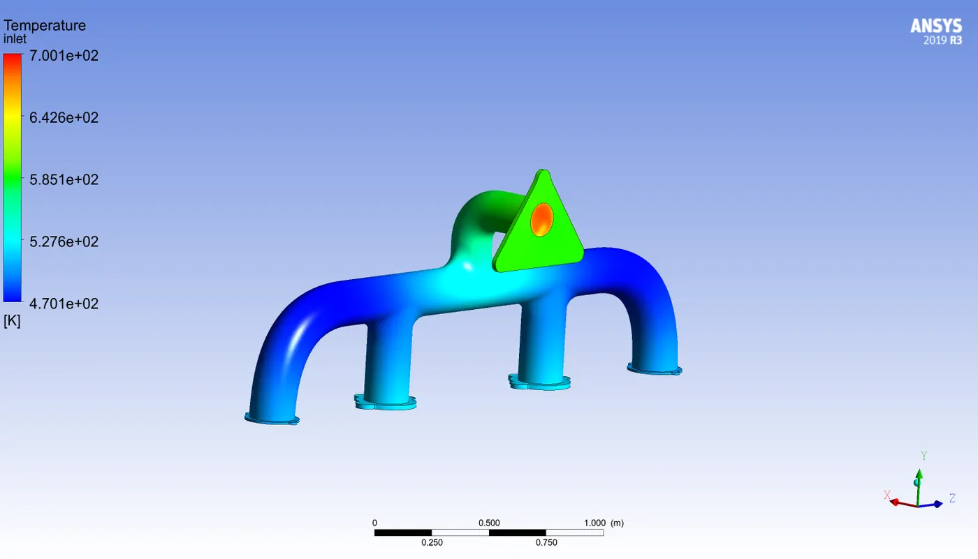
Temperature distribution front view :
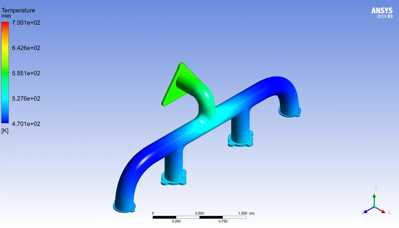
Temperature Distribution back view :
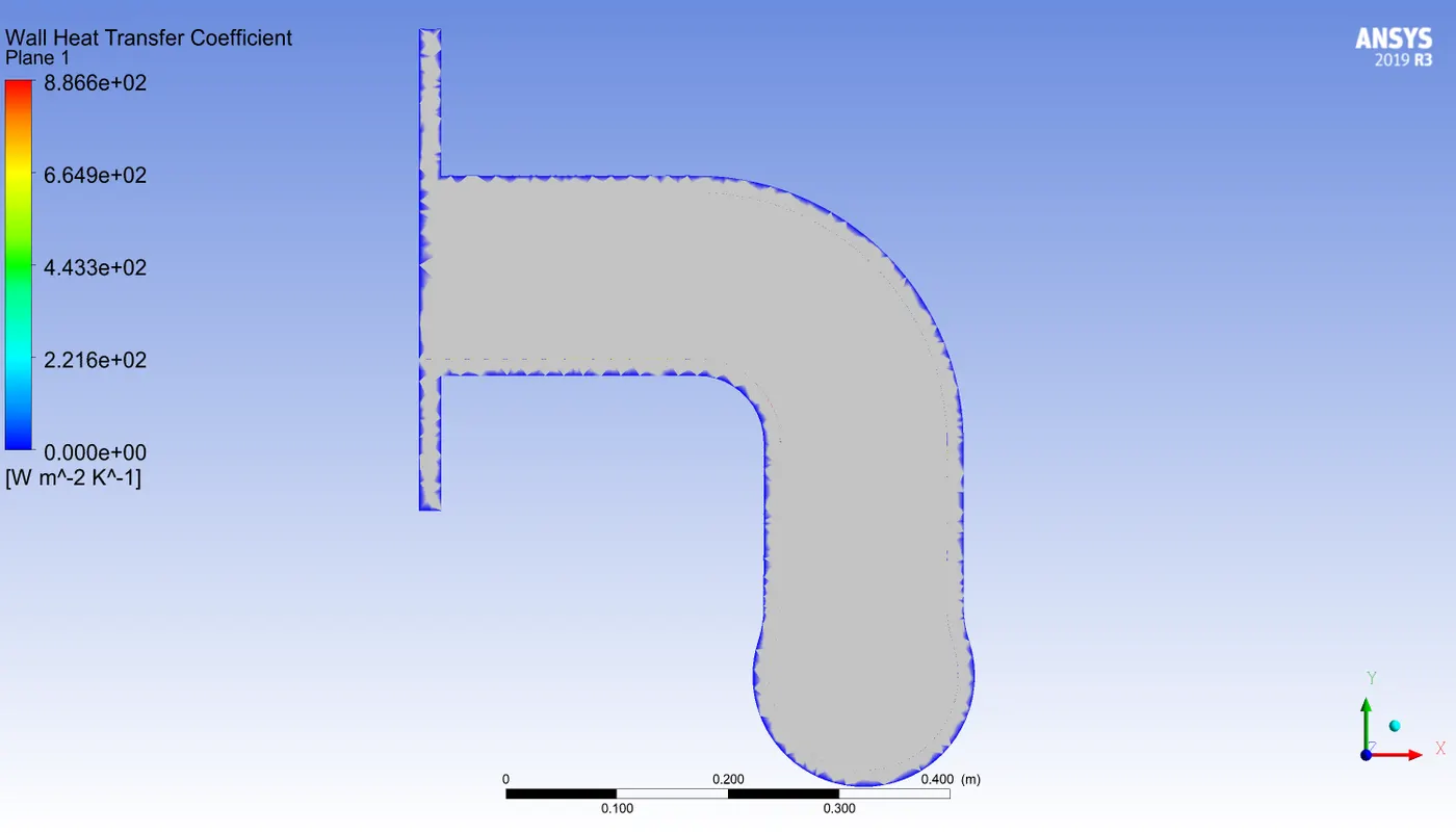
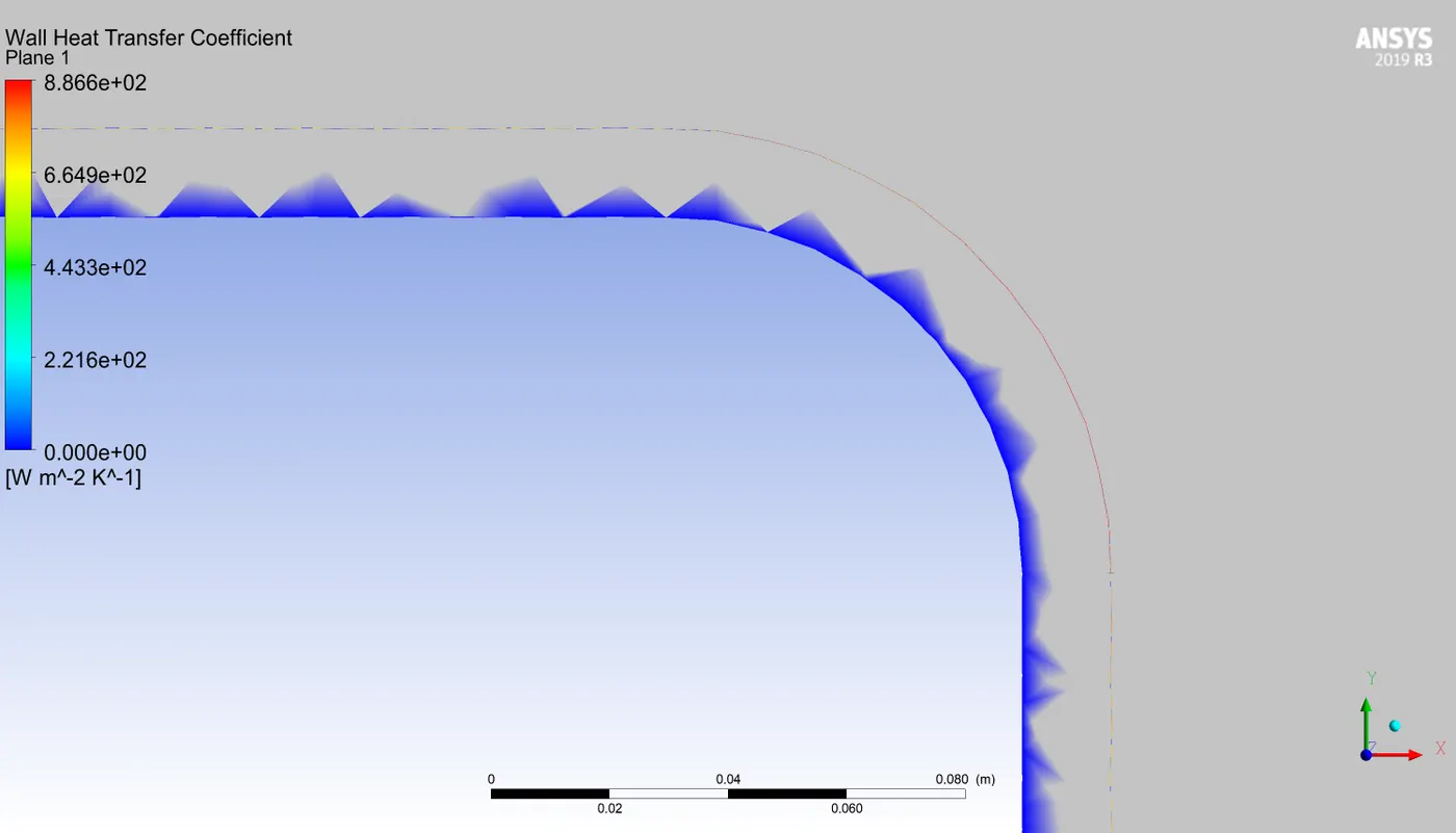
heat transfer coefficient :
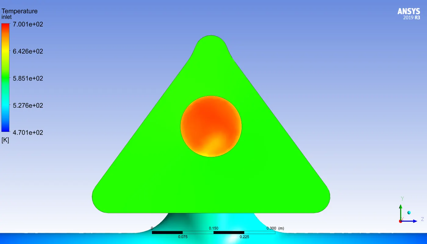
Outlet temperature variation :
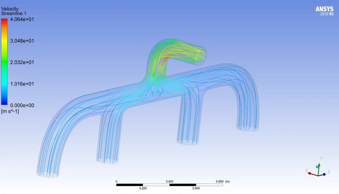
Streamline variation :
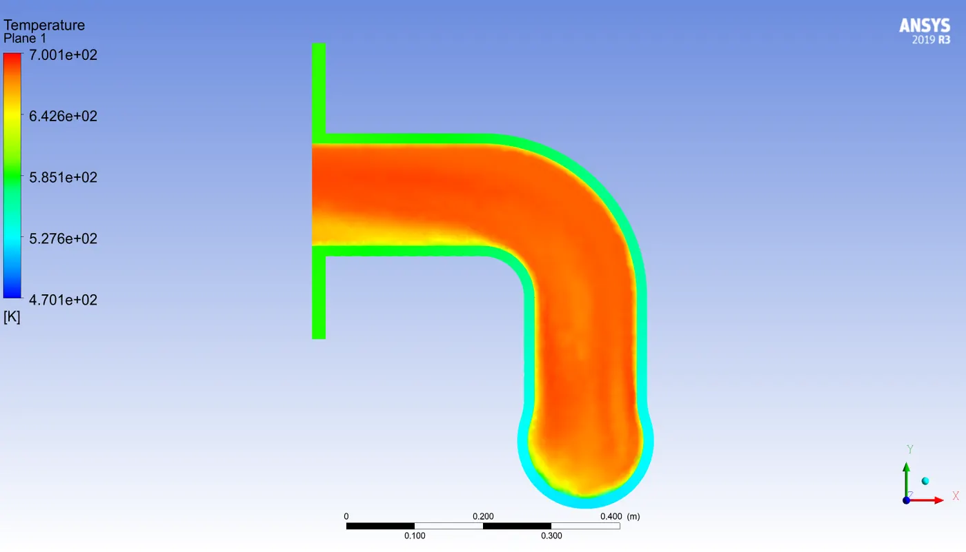
temperature distribution in the plane :
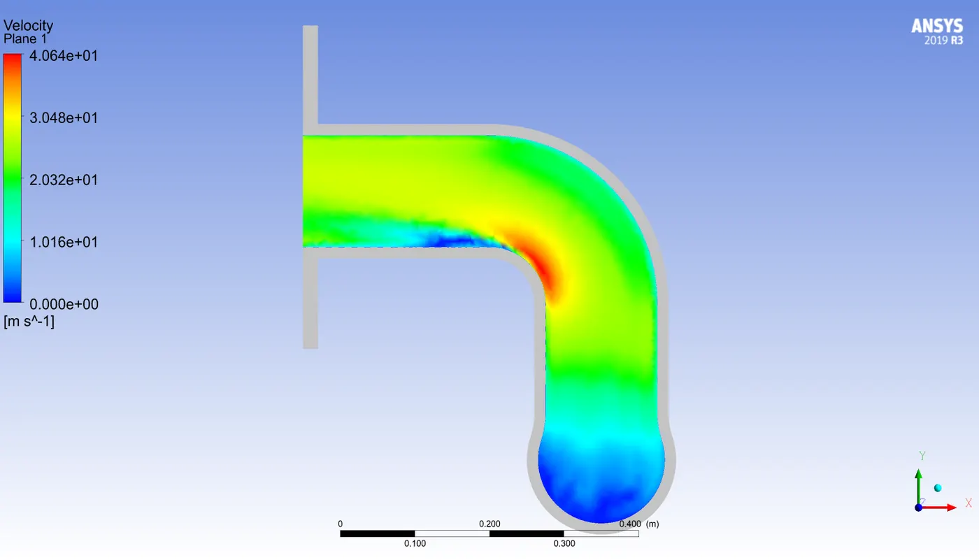
Velocity distribution in the plane :
 \
\
Animation
Animation - Particle Track - temperature
| Mesh Type | Heat transfer coefficient (W/m^2-K) |
| Non-Refined |
21.293912 |
| Refined |
21.124894 |
Conclusion :
-
Here the convection type is forced convection type and for forced convection type situation h should like between 10- 100 and in the performed simulation, it is near 21
- Fluid velocity suddenly starts increasing on passing through the junction. it is because of the change in the area and due to continuity.
Validation :
From the conservation of energy :
`sumQ_(i n l et) = sumQ_(out) + `heat absorbed by wall`
`sumQ_(i) = Q_1 + Q_2 + Q_3 +Q_4`
`sumQ_(i) = 320458.12`
`sumQ_(out) = 300964.54`
``heat absorbed = 218913.86`
There is some error in right side beacuse it is a numerical solution, but it approximately becomes equal to left side.
References :
- Perelman, T. L. (1961). "On conjugated problems of heat transfer". International Journal of Heat and Mass Transfer.
- Luikov, A. V.; Perelman, T. L.; Levitin, R. S.; Gdalevich, L. B. (1971). "Heat transfer from a plate in a compressible gas flow". International Journal of Heat and Mass Transfer.
- Patankar, S. V., 1980, Numerical Heat Transfer, and Fluid Flow. Taylor & Franci