Ahmed Body Challenge
1. Introduction
Standard wind tunnel models, also known as reference models, calibration models, or test check-standards are objects of relatively simple and precisely defined shapes, having known aerodynamic characteristics, that are tested in wind tunnels and Ahmed body is an example of one of those model. Ahmed body is nothing but a basic car body, it is designed in such a way that we can get a rough estimation of desired aerodynamic quantities, and their variation around a car. It is modified in such a way that its shape is simple enough to allow for accurate flow simulation but retains some important practical features relevant to automobile bodies. In this simulation, we are trying to perform an external simulation over a body
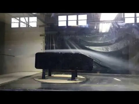
Real-World Model of Ahmed Body
2. Solving and Modelling Approach
2.1 Governing Equations :
`nabla.vecV = 0` Continuity equation
`rho*(DvecV)/(Dt) = -nablap + rho*vecg + mu*nabla^2.vecV` Momentum Equation
2.2 Environment
All the simulations were performed in commercial CFD software ANSYS Fluent v2019R3.
The complete analysis is being done at Air temperature = 300K. Inlet velocity is equal to 25 `ms^(-1)` so at 300K Velocity of sound 330 ms^(-1)
so, Mach number = `25/300 = 0.075` which is clearly less than `0.3` and hence the flow will be considered as incompressible
And the air is considered as fluid and expected to be turbulent flow and with following k -`epsilon` model
3. Pre-processing and solver setting
3.1 Geometry
A Prescribed dimension Ahmed body was developed with its length = 1.04 m
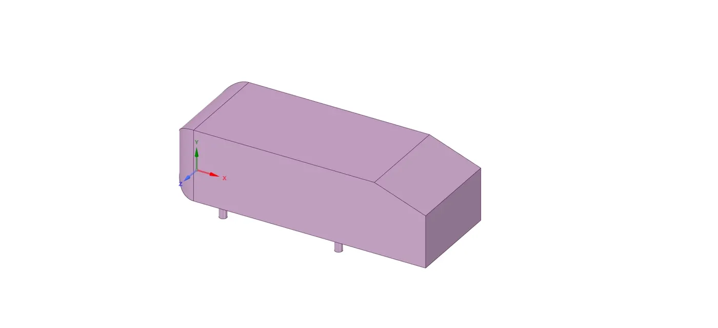
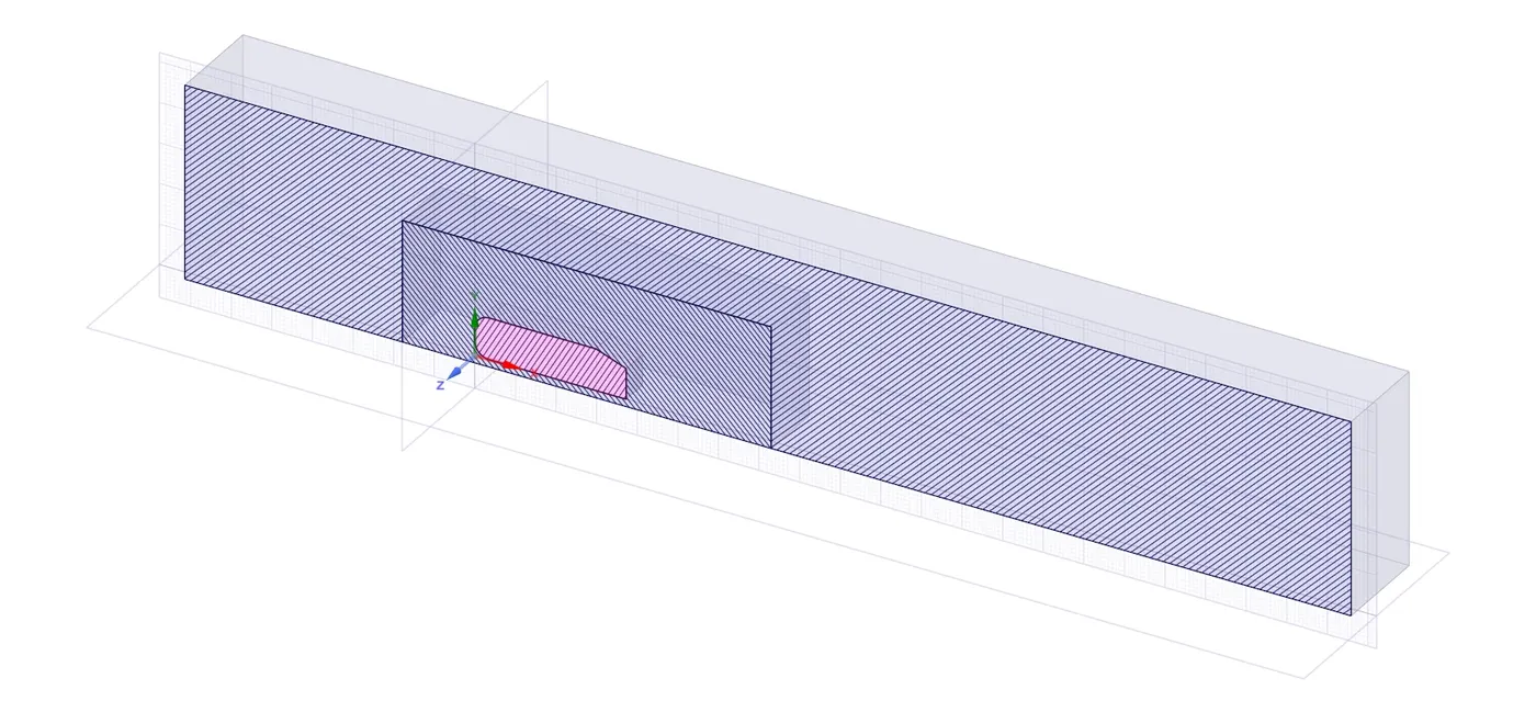
It was enclosed than in a cuboid which was later treated as a domain
Front and Side view of a larger enclosure
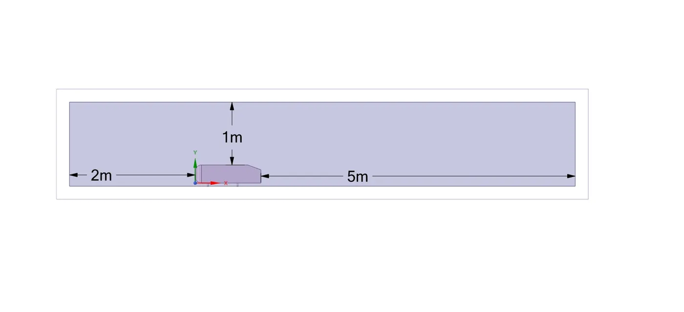
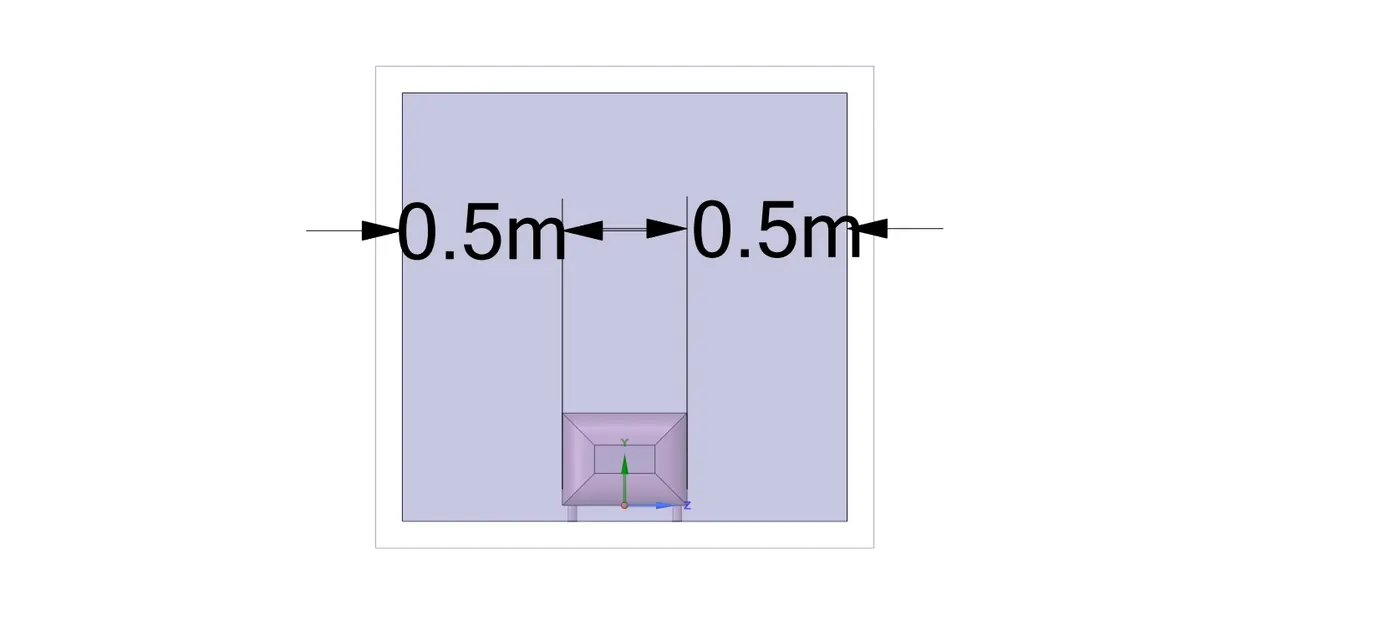
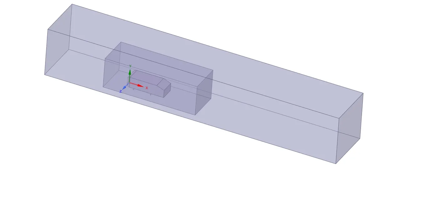
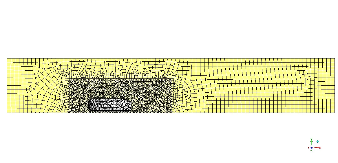
For mesh refining purpose, a smaller enclosure was added inside a large enclosure
Front and Side view of the smaller enclosure
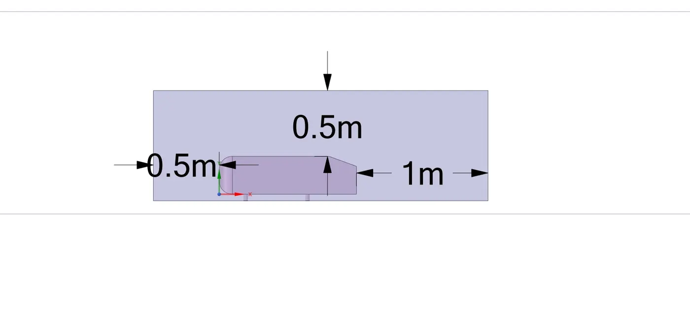
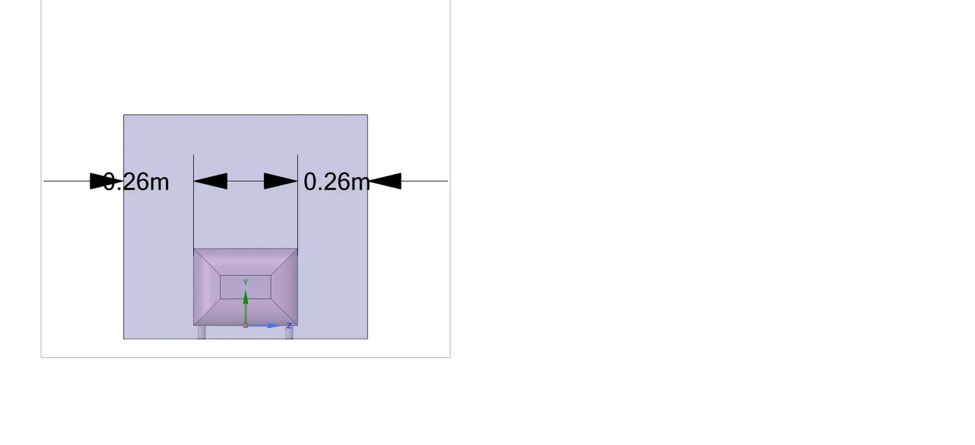
Final View of the complete geometry setup
(Note - Ahmed body is suppressed for physics here, because we don't want results inside the body rather we want the results over the body and outside it hence there is no need for the internal portion of Ahmed body for performing simulations and results will be symmetric about XY plane)
As the domain is completely symmetric about XY plane so we will rather split it in half and will perform simulation over half of the portion so we can reduce our time as well as simulation cost
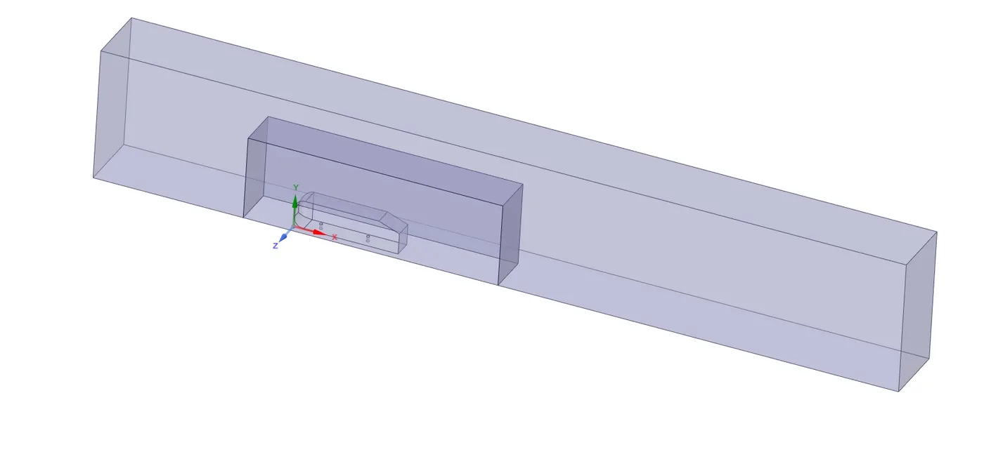
The intersection of cross-sections of both enclosure
3.2 Meshing
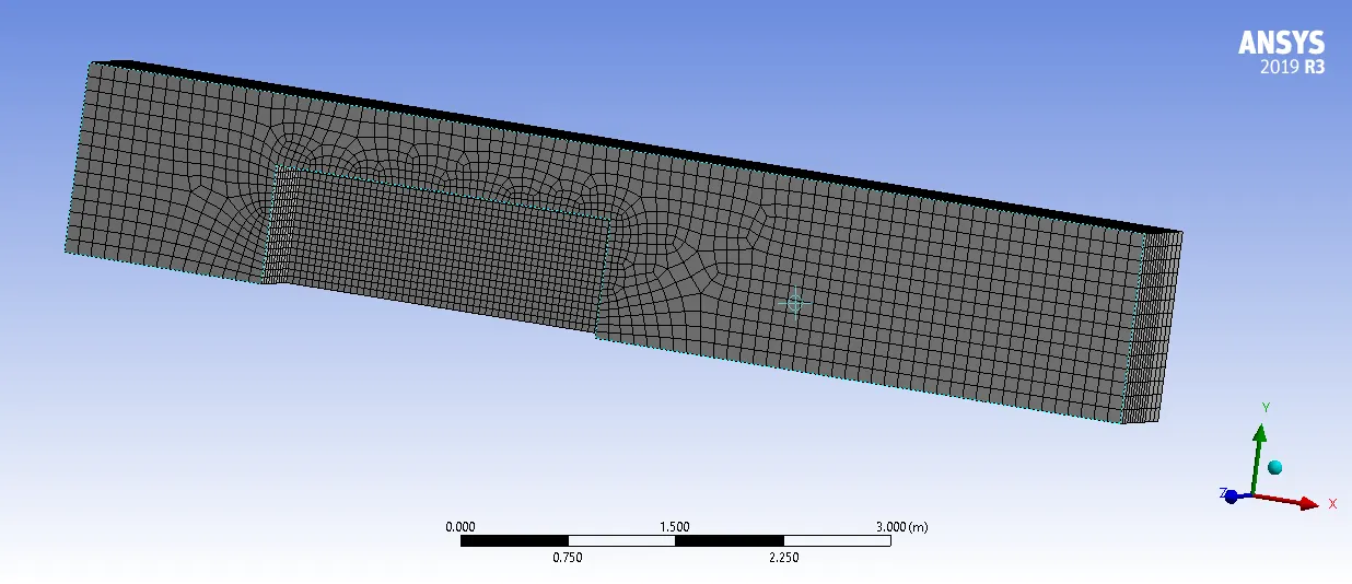
Outer enclosure
For the outer enclosure, element size was chosen 0.1 m with Adaptive sizing turned on and the multizone method was used over it
Inner enclosure
On inner enclosure element size of 0.05 m was chosen
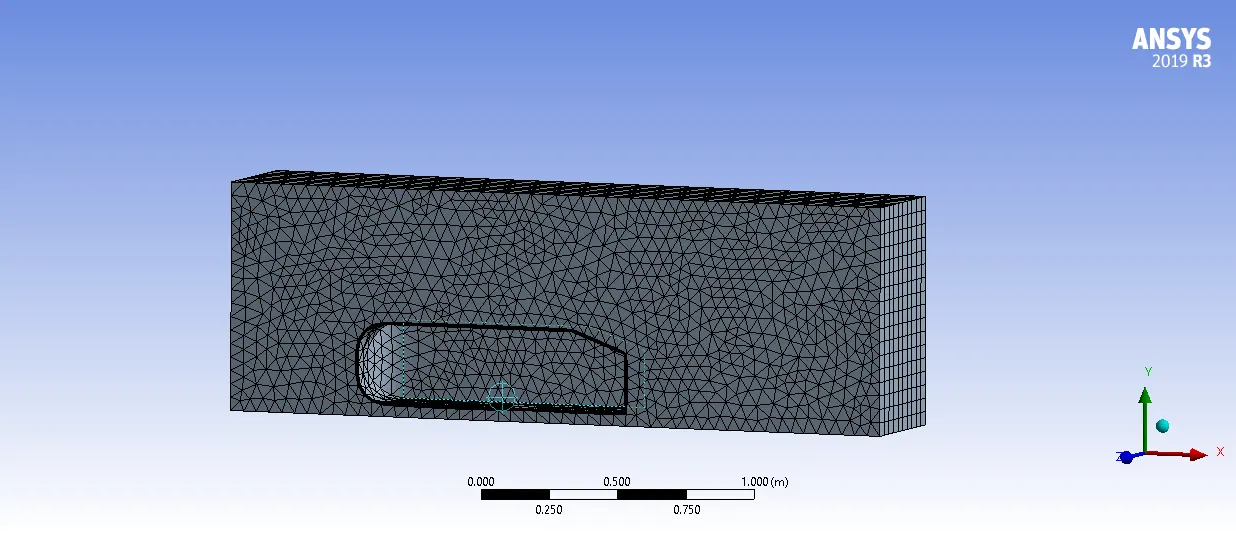
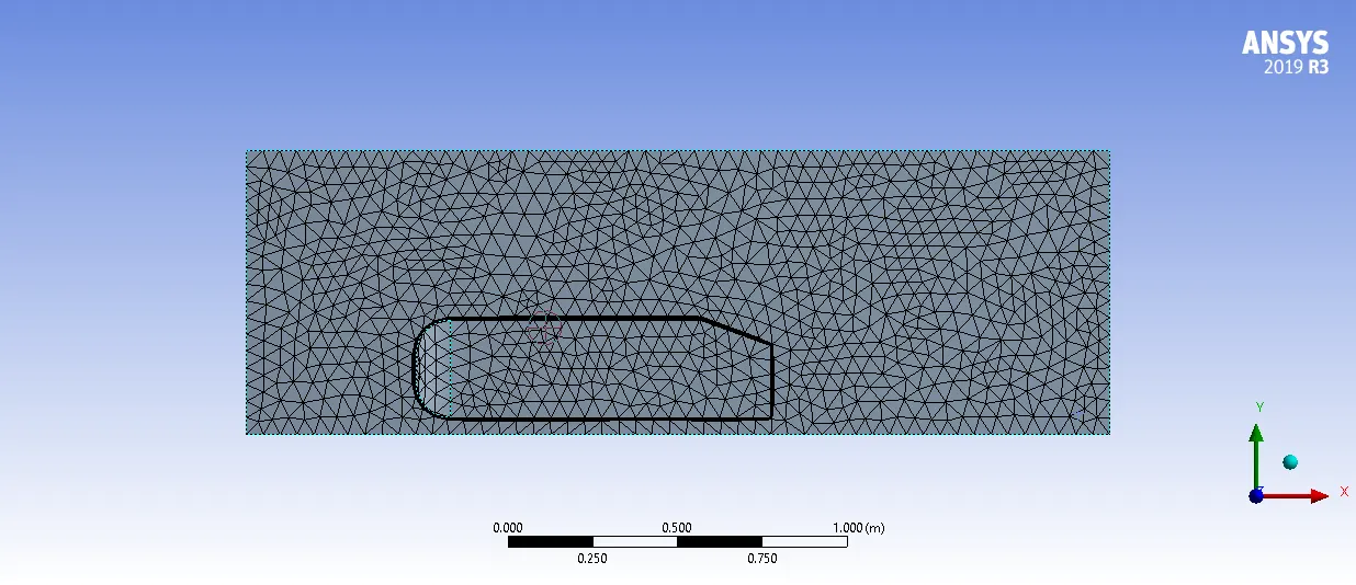
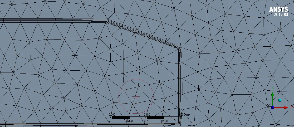
to improve results and accuracy an inflation layer of 0.012446m was used around the Ahmed body wall with 5 layers and a growth rate of 1.2
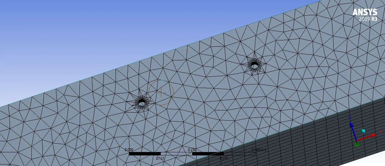
and mesh quality of support wall was improved using face meshing on supports of the Ahmed Body with an element size of 0.005m
3.3 Boundaries
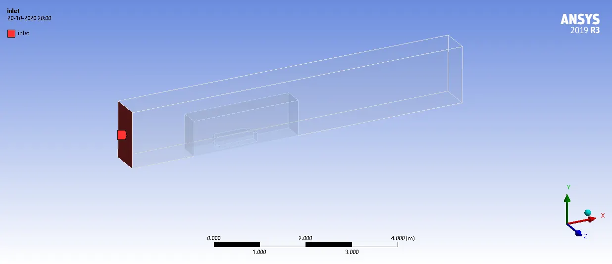
INLET - The inlet for domain
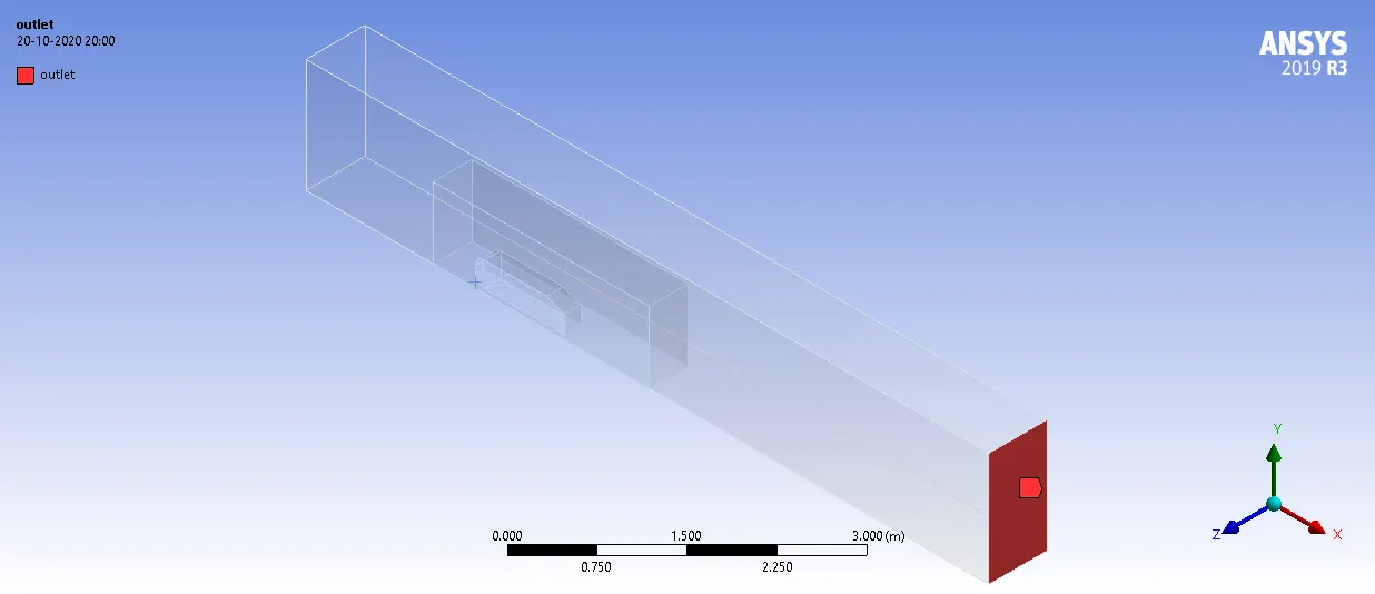
OUTLET - The outlet for domain
WALL = The stationary wall of Ahmed Body
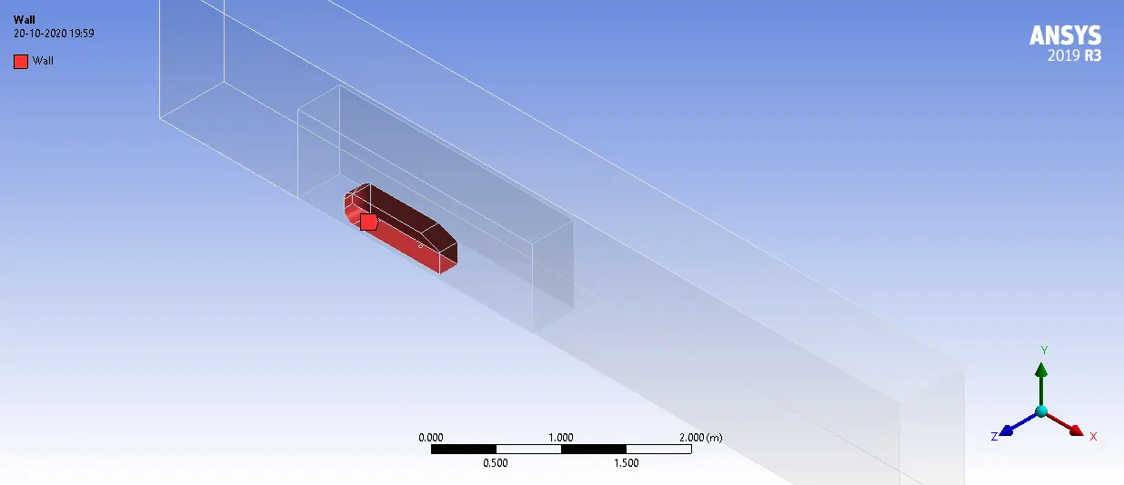
Rest all walls were marked as symmetry
3.3 Solver settings
K-`epsilon` model (Turbulent) was used as a Visocus model
A steady-state Solver was used
Reference values:
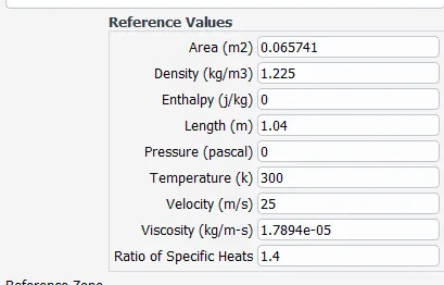
Fluid properties :
Here Fluid is Air
| Density | 1.225 |
| Specific Heat Capacity | 1006.43 |
| Thermal Conductivity | 0.0242 |
| Viscosity | 1.7894e-05 |
Boundary Conditions :
- Inlet - Velocity Inlet - Velocity = 25 `ms^(-1)`
- Outlet - Pressure Outlet - Gauge pressure = 0
- Wall - Stationary outer wall of Ahmed Body
- And Rest all faces of Domain are considered as Symmetry
Initialization :
Hybrid Initialisation
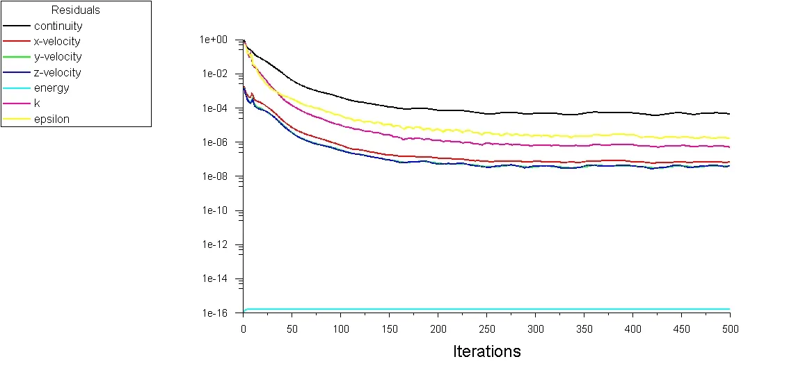
A total of 500 iterations were performed
4. Results
4.1 Graphs
Residual
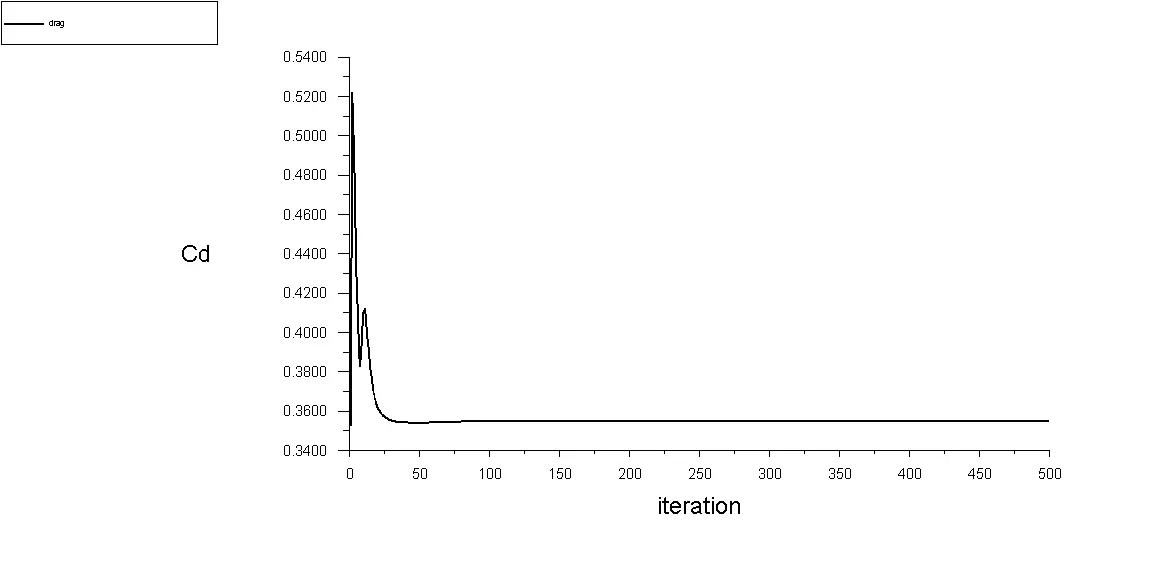
Drag coefficient `C_(d)`:
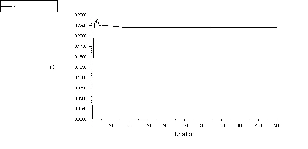
Lift Coefficient `C_(l)` :
4.2 Contours
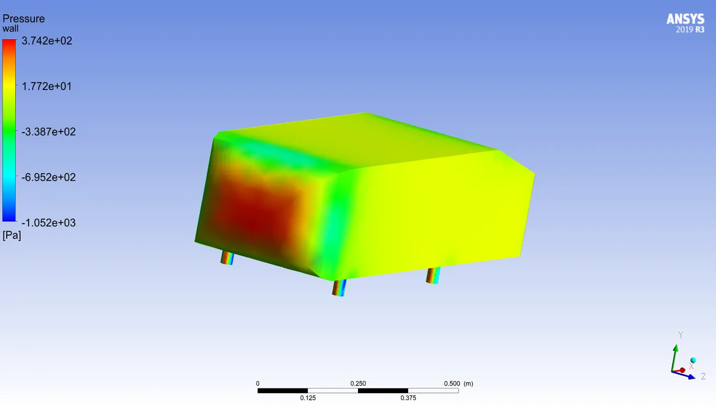
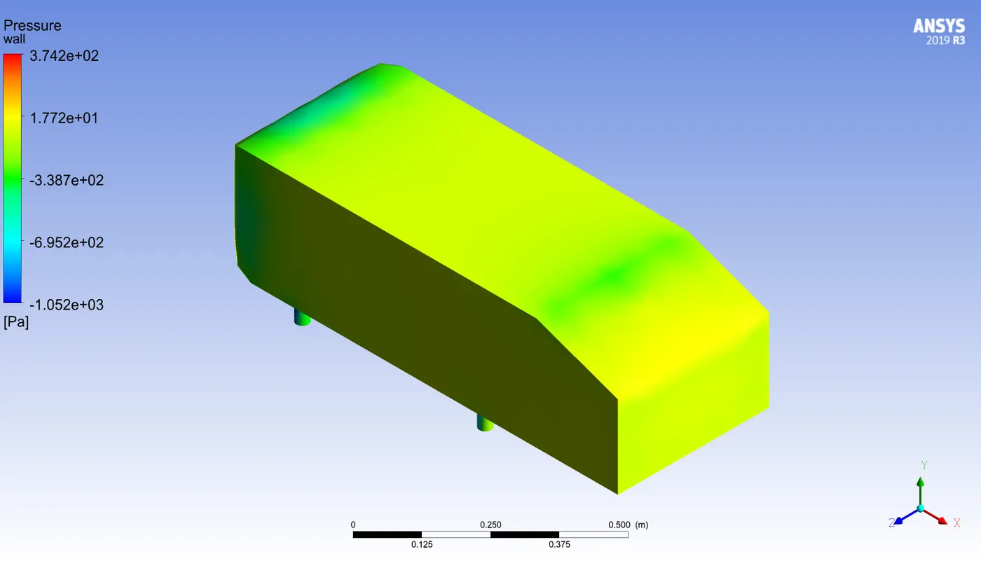
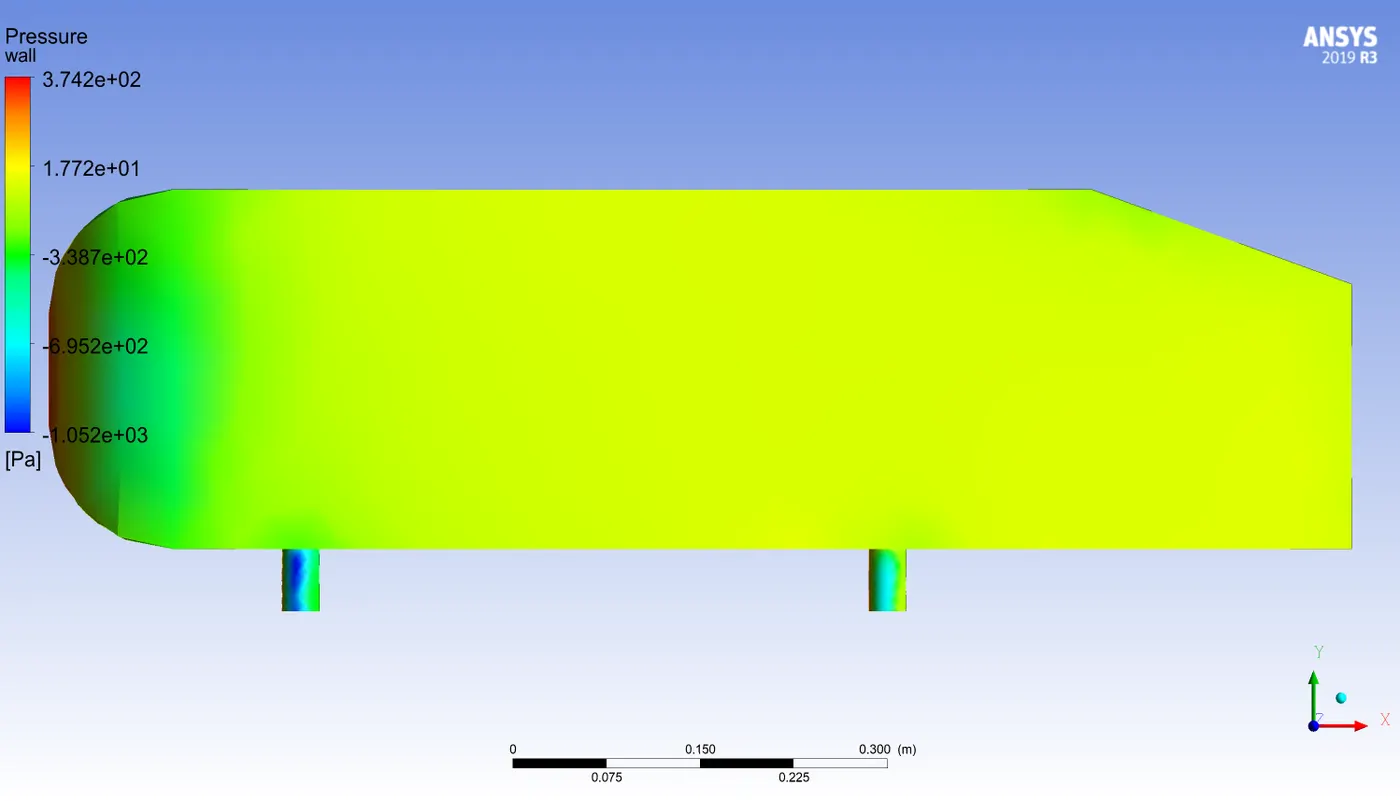
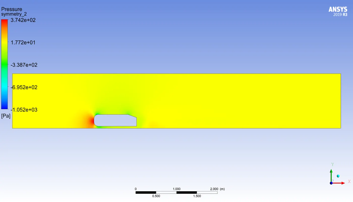
Pressure distribution over Ahmed body
(Note - Pressure is negative in some portions)
Pressure contour
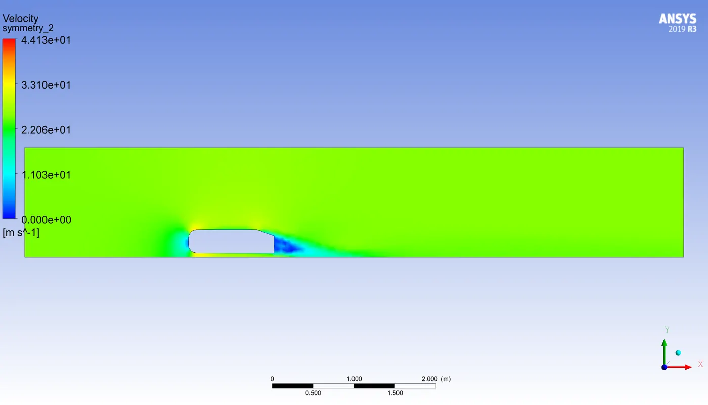
Velocity Contours (XY plane)
Velocity Contours - Vectors
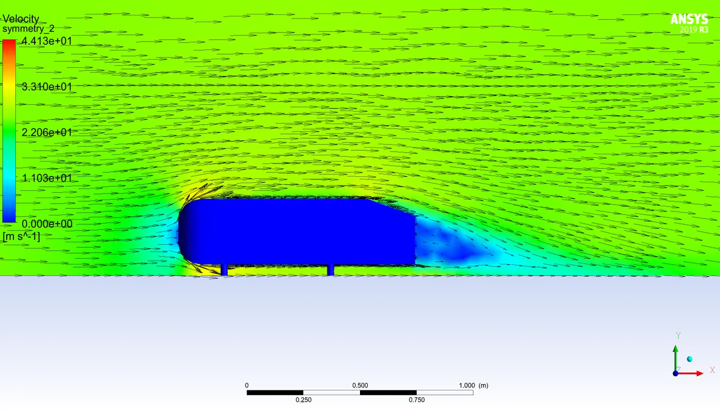
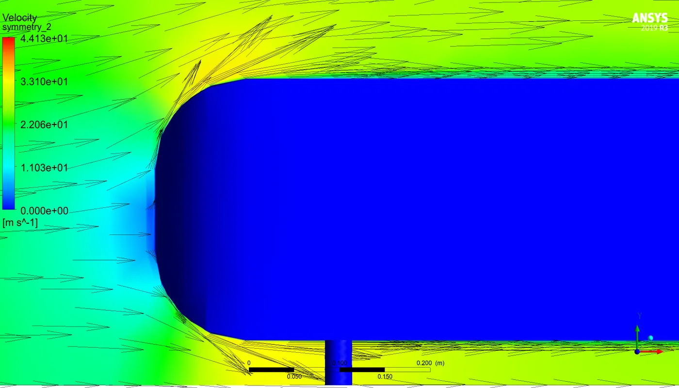
Velocity Contours - Vectors - Enlarged - Front (wake formation)
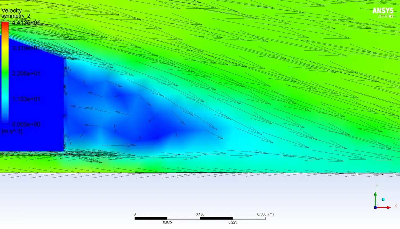
Velocity Contours - Vectors - Enlarged - Rear
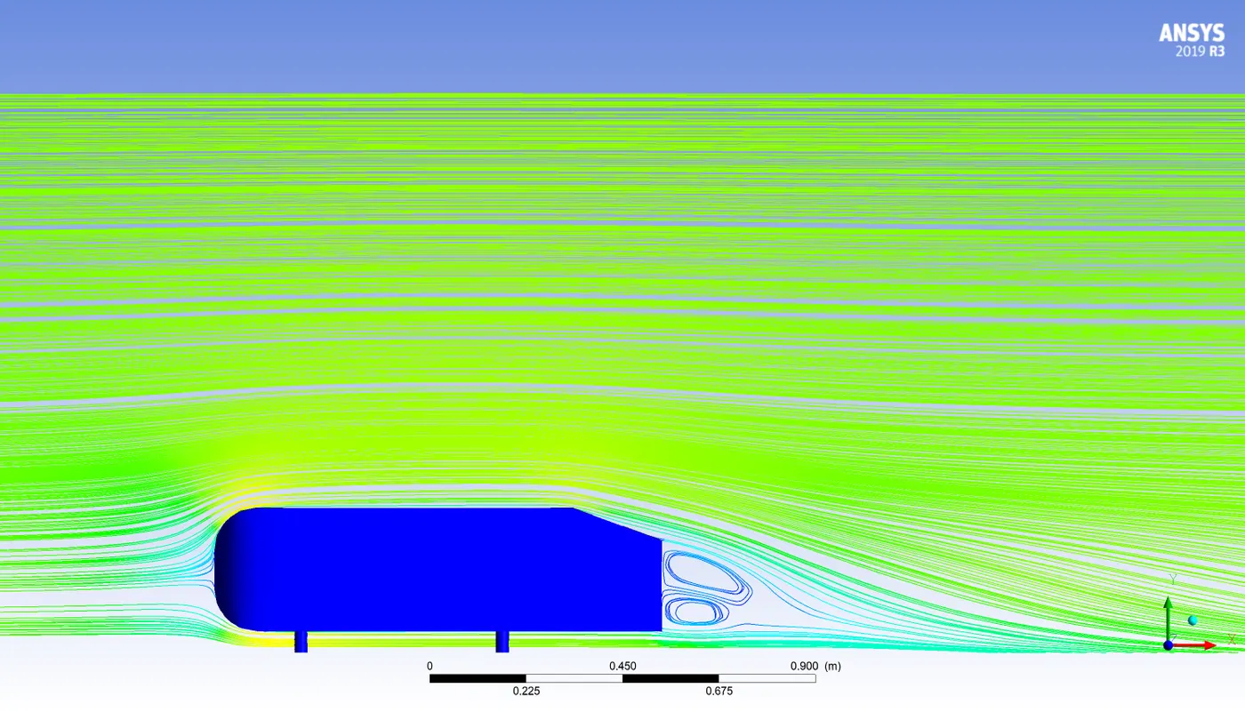
Velocity Contours - Streamlines
4.3 Grid Independence Test
Grid 1: The original gird
Inner enclosure Mesh element size = 0.05 m
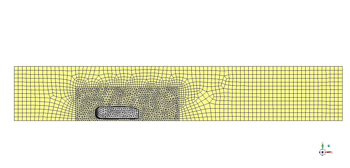
Grid 2
Inner enclosure Mesh element size = 0.04 m
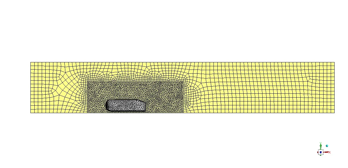
Grid 3
Inner enclosure Mesh element size = 0.035 m
| Grid Number | Element Size (m) | Cd | Cl |
| 1 | 0.05 |
0.355 |
0.220 |
| 2 | 0.04 |
0.338 |
0.248 |
| 3 | 0.035 |
0.332 |
0.239 |
4.4 Validation
It can be seen that after element size less than 0.04` `C_(d)` is remaining constant to the value of 0.33, which is the desired value
5. Conclusion
To explain results better, the same simulation was performed with element size = 0.025 m
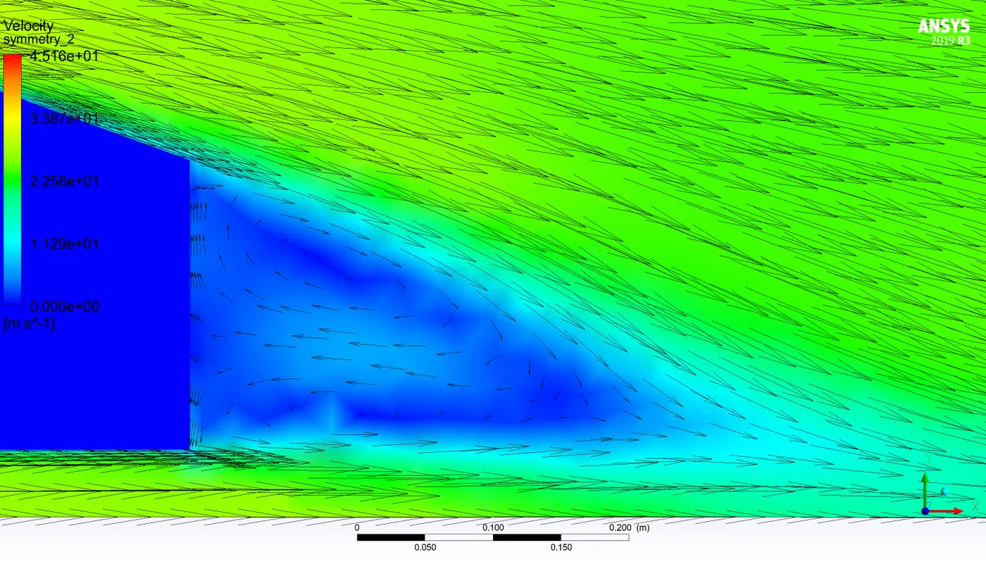
What is the wake?
The wake is the region of disturbed flow (often turbulent) downstream of a solid body moving through a fluid, caused by the flow of the fluid around the body. It can form due to the region of recirculating flow immediately behind a moving or stationary blunt body, caused by viscosity, which may be accompanied by flow separation and turbulence
In our case, the wake formed, looked like this (arrows indication velocity direction)
Significance of point of separation
So if we see the figure of rear and front of Ahmed body velocity distribution the air is striking with a velocity of 25 `ms^(-1)` to a body at rest, at the rear of Ahmed body it is striking perpendicularly to the surface so the change in momentum will be
`P_(f) - P(i) = 0 - mv`
`F prop deltaP`
so higher the change in momentum more will be the force that's why pressure is very high at the rear end but as we move upwards it's striking at some angle because the surface is not always parallel to Y hence at the curvature of the top surface, there will be an abrupt change in momentum like before but in this case, it will be less as compared to the vertical wall and on the above surface.
But on a horizontal plate, in this case fluid will act somewhat similar to flow over a flat plate. Since there will be a large amount of force generation, but the fluid is also moving along the x-axis and due to force an adverse pressure gradient will form that leads to the formation of Boundary layer separation. It usually happens when there is flow against an increasing pressure gradient. This leads to detachment from surface i.e. first this leads to 0 velocity gradient and then in the site direction of flow (which is also responsible for circulations).
At point of separation
`tau = mu*(delu)/(dely)` becomes zero hence there will be no shear stress at that point afterwards there may be a counter flow if pressure gradient increase further.
Negative pressure gradient in the wake region
In CFD post the negative pressure is the Gauge pressure and not the absolute pressure.
So here it means the pressure in the wake region is less than atmospheric pressure, and wake is a low-pressure region because of the continuous loss due to viscosity in fluid the pressure drops.
6. References
- Fluid Mechanics By F.M White
- Fluid Mechanics by John Cimbala and Yunus A. Cengel
- Fluid Mechanics and Fluid Machines by SK Som, Gautam Biswas, Suman Chakraborty
- wikipedia.org
- http://www.maths.manchester.ac.uk/~suzanne/teaching/BLT/sec4c.pdf