Frequency Analysis of a rotating shaft
Aim:
To find out the critical frequencies of a rotating shaft in Solidworks.
Objective:
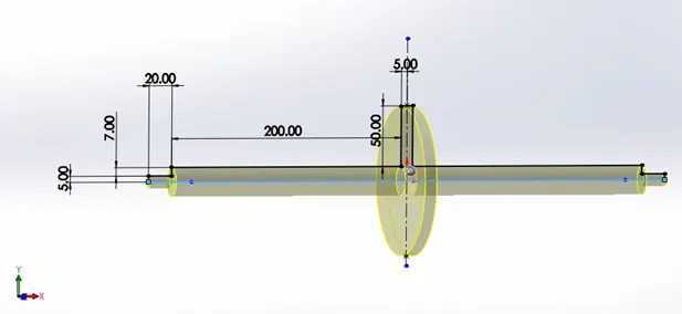
- Model a rotating shaft in Solidworks according to the image shown below.
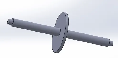
Hint: Conduct a frequency analysis and apply a bearing fixture on the stepped face of the rod at the two ends and perform the analysis.
- Find out 5 mode shapes and list the resonant frequencies.
Overview:
With FEA we can perform 2 types of Analysis, Static and Dynamic.
- Static Analysis is used to test for Strength due to static load. Here we are looking at stress distribution of a component once it achieves static equilibrium with the static load. E.g., Deformation and stress on engine frame due to engine weight.
- Dynamic Analysis is used to test for Strength due to time varying dynamic load e.g., Shock, impulses, oscillatory loads etc.
Consider a Mass-spring,
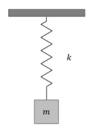
On the application of external force, the spring deflects until the opposing spring force equals external force. Now, the stiffness of the spring is analogous to the elasticity of the material and the mass is to its density.
Now, if this Spring-mass system is hit with a hammer (an impulse force), the basic response exhibited by this system is oscillation. While this spring-mass oscillate about mean position, it experiences structural deformation and hence stress. We can assume this spring-mass system to be a machine element like shaft, bearing, gears in gear box, etc. When these machine elements are subjected to an external force, they also experience same oscillations due to their inherent elastic property.
Now, in order to characterise this oscillation, we have 2 measures – Amplitude and Frequency. That are the fundamental result of any vibration analysis. This is critical feedback that we have to improve product design for vibrating environment.
We have 5 types of Vibrational Analysis that can be performed with solidWorks simulation.
- Frequency/ Modal Analysis
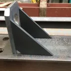
It is a quick way to predict vibrational characteristics of a part or an assembly without having to input the vibration source to the software. Here, we want to ensure that the component is stiff enough to be able to tolerate any potential vibrational loading. For this we have 2 outputs, mode shape of the component and its natural/ resonant frequency. We are basically trying to ensure that the frequency of vibration dose not fall inline with the resonant frequency, to avoid resonance. Additionally, studying the mode shapes of the component gives us an idea how a component could vibrate, with this information we can modify the component by adding ribs, gusset plate or even more material in order to prevent the component from vibrating in certain manner.
So, this analysis provides Mode shapes and Natural frequency. No force input is necessary. It is a measure of object stiffness. And also the system is undamped.
Now, if we want to see how a componet respond by putting a vibration source or a dynamic load as an input. Following methods are chosen.
- Modal time history or transient analysis
This analysis takes time-based forces as an input for the component under test. As an output it provides plots for stresses, displacement and acceleration response as a function of time. This way we are able to study how our assembly vibrate in real time.
- Harmonic Analysis
- Random Vibration
- Response spectrum Analysis
In above 3 analysis we are taking various frequencies as an input load, to understand the amplitude of vibration in order to predict failure. For instance, in Harmonic analysis, we replicate the vibration of the component placed on shaker table where the frequency is gradually varied to determine the amplitude at different frequency inputs.
Resonance frequency could be used to make better design decisions, e.g., we may want to put support where the amplitude is highest to arrest large amplitude or reduce wear-and-tear due to vibration etc.
Steps Taken:
- Creating Model (all dimensions are in mm).
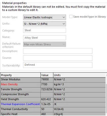
- Assigning Alloy steel as Material for the shaft.
- Applying Bearing Fixtures at steps provided in the shaft.
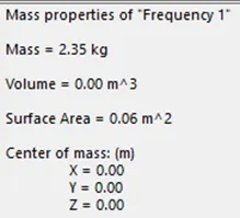
- Activating gravity to account for the weight.
- Creating mesh.
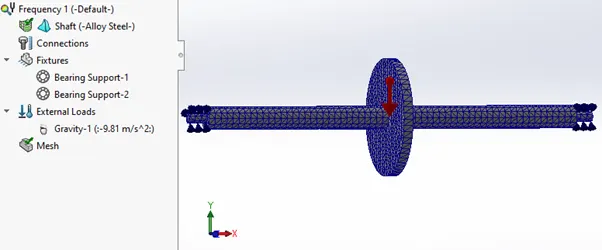
Here ‘External Load’ should not be mistaken for vibration source because the frequency analysis dose not require it. It is needed if there is a static pre load exists in the component, this will affect the overall stiffness of the component and hence its natural frequency.
- Running the Frequency Analysis.
The following error may be encountered while running the study. This is because we are taking the gravity into account.
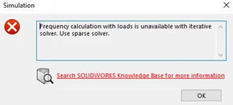
- Resolving the error.
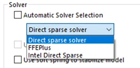
Go to the properties by right clicking on the ‘Frequency tab’.
Select Direct sparse solver and make the mesh coarse.
- Getting the Results.
Now we have got 5 Amplitude plots which will give us an idea of how the component will vibrate and what is the most probable vibration shape.
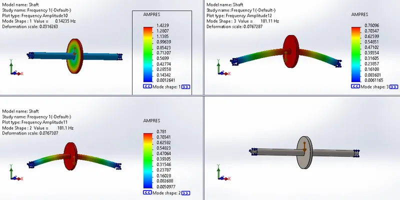
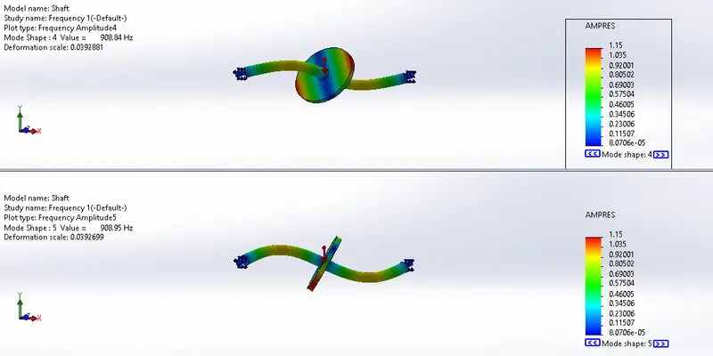
Each of these shapes have a natural frequency associated with them. This gives us an idea of vibration shape the component will take when exited by a source of a given frequency.
Observations:
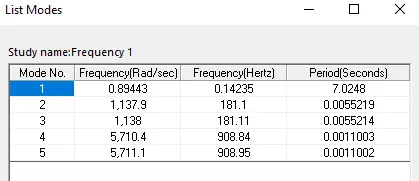
|
Mode no. |
Critical/Resonance Frequency (Hz or rps) |
Critical/Resonance speed (RPM) = 60 * rps |
|
1 |
0.14235 |
8.541 |
|
2 |
181.1 |
10866 |
|
3 |
181.11 |
10866 |
|
4 |
908.84 |
54530.4 |
|
5 |
908.95 |
54537 |
The shaft should not be operated at or near by the RPM mentioned above, as in those angular speed the shaft will oscillate at higher amplitude (due to Resonance).
Conclusion:
- To make the shaft operate at higher speed we may consider reducing the length of the shaft and adding more thickness to increase the stiffness of the shaft.
Since,

where s = stiffness, m = mass and n = Natural frequency (in Hz). We can see that natural frequency is proportional to the square root stiffness. So, by increasing the stiffness natural frequency will also increase and we will have higher operating range for the shaft.
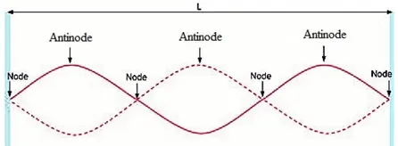
- We can also provide support to the shaft at the antinodes by bracing it with the help of another support bearing. Like a centre support bearing on driveshaft of a car.