Motion analysis Internal Geneva Mechanism.
AIM:
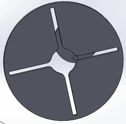
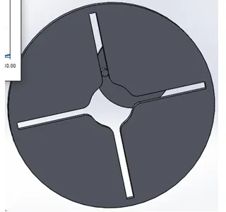
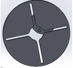
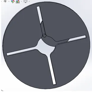
- To create 3D model for driver and driven wheels for internal Geneva mechanism using SolidWorks and assemble those parts to make complete mechanism.
- Perform motion analysis by rotating the driver wheel at 10 and 20 rpm.
- To Plot (with and without Precision contact option):
- Contact force between Driver and Driven wheel vs time,
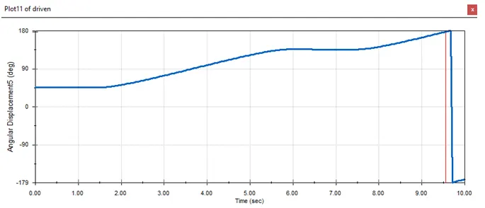
- Angular Displacement of Driven wheel vs time
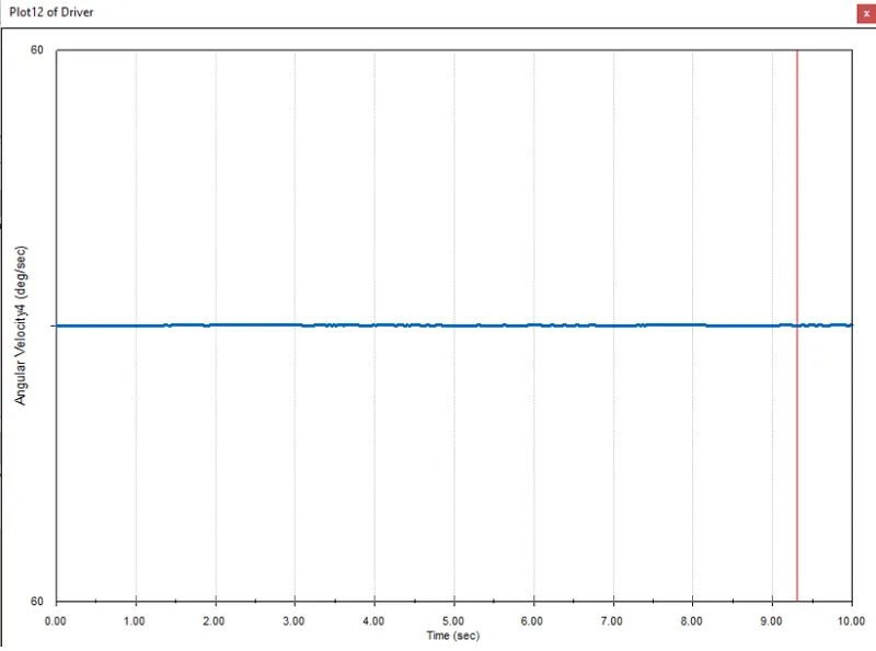
- Angular velocity of Driver vs time
- Study the effect on the plots.
Basic Definitions:
- Rotational Motion
A motion in which all the internal particle move in a circular path about a fixed axis.
- Linear Displacement (s) & Angular Displacement (θ)
In linear motion, we use 's' to quantify the linear distance travelled. In angular motion, we use 'θ' for the same to quantify the angular distance, and it is measured in radians.
- Linear velocity / tangential velocity (v)
V = r ω
- Angular velocity (ω)
Angular velocity is the number of radians covered per second. It is same for all points in the rotating body.
- Contact force or Surface force
It acts on each surface element of the body and is exerted by direct mechanical contact some examples are friction, normal, pushing, pulling etc.
Introduction
Geneva mechanism, also called Geneva Stop, one of the most commonly used devices for producing intermittent rotary motion, characterized by alternate periods of motion and rest with no reversal in direction. It is used in movie projectors, movie cameras, analogue watches, indexing (i.e., rotating a shaft through a prescribed angle).
There are 3 types of Geneva mechanisms namely internal, external and spherical.
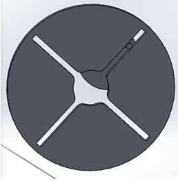
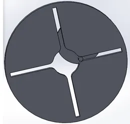
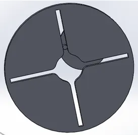
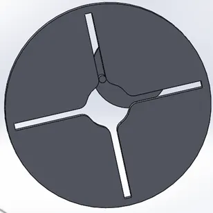
If the Driven wheel has 4 slots, then for each rotation of Drive wheel it advances by one step of 90 degrees. If the Driven wheel has n slots, it advances by 360deg / n per full rotation of the Drive wheel.
As the Driven member is rotated by transfer of contact force from Driver’s pin, excessive impact could be a problem. To minimise the impact, we should make sure that the Driver’s pin transfers the force to the Driven member, gradually.
Note:
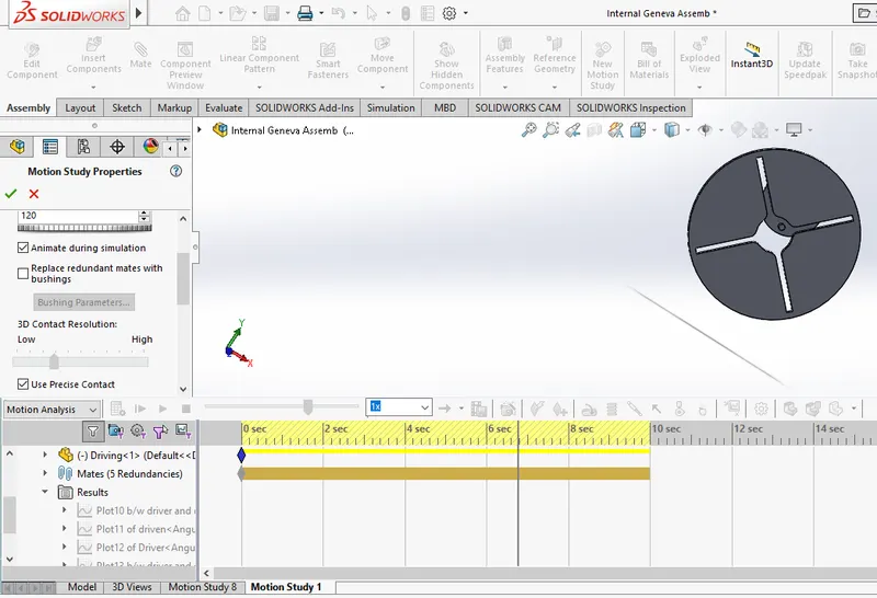
- Time line in the ‘Motion study’ represents time-based changes. For examples we can turn on/off, hide/show a component in feature tree in solid works and that will happen live, but in time line we can make sure when it will happen and can toggle between different states.
- There are 3 Study types in Solid works motion study:
- Animation b. Basic motion c. Motion Analysis
- Here, we will make use of “Motion Analysis” feature as it helps in engineering analysis for example by utilising this, we may able to calculate rate of movement, torque and forces involved, which may not be calculated by using “Basic motion” or “Animation”.
- The analysis done using “Motion analysis” can be exported using Results and Plots.
- Material used for Driver and Driven wheel is Steel(dry).
- The study is performed for an interval of 10 seconds.
- Both wheels rotate in anticlockwise direction.
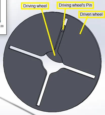
Wheels Measurements:
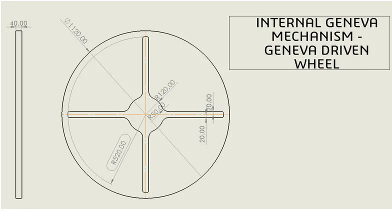
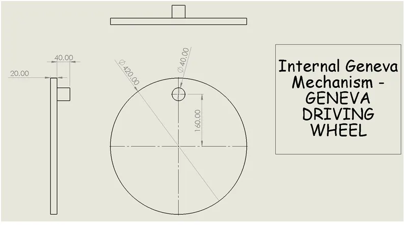
Results:
- Plots at 10 rpm:
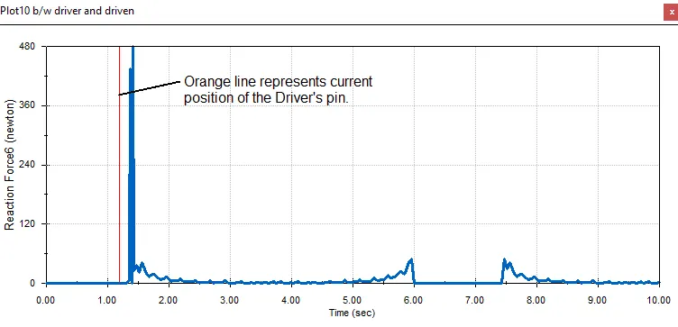
1.1. Contact force between Driver and Driven:
1.2. Angular Displacement (deg.) of the Driven wheel vs time:
1.3. Angular Velocity of Driver vs time
2. Plots at 10 rpm with Precise contact and 60 Frames per second
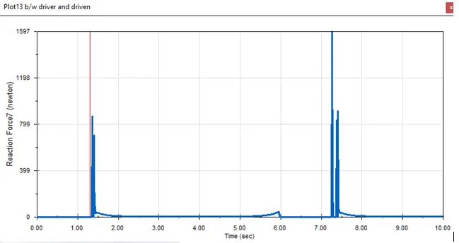
2.1 Contact force between Driver and Driven vs time:
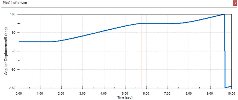
2.2. Angular Displacement (deg.) of the driven wheel vs time:
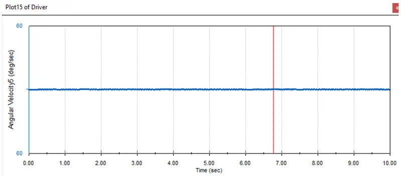
2.3. Angular Velocity of Driver vs time:
3. Plots at 20rpm with Precise contact and 120 Frames per seconds
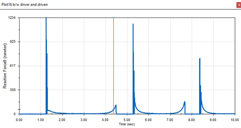
3.1. Contact force between Driver pin and Driven vs time:
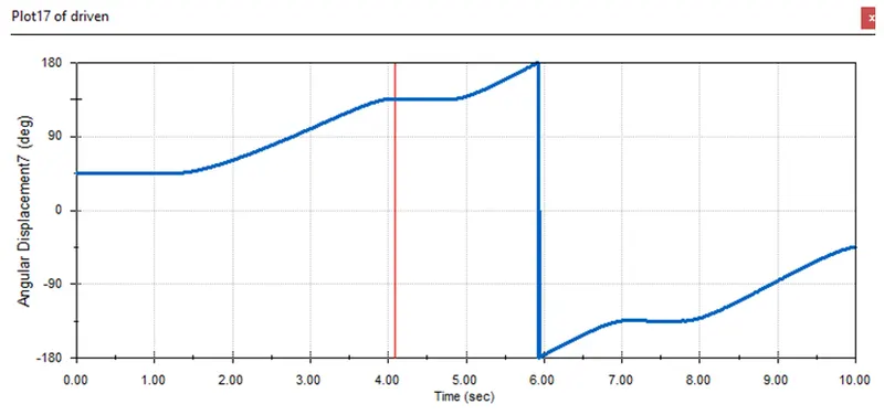
3.2. Angular Displacement (deg.) of the driven wheel vs time:
3.3. Angular Velocity of Driver vs time:

Conclusion:
- The “Precise contact” gives relatively accurate results. How? When comparing contact force curve for 10 rpm (with and without precision), precision curve is smooth. There is variation in peak force too, plot 1.1. gives peak force at 1.4sec of 480N whereas plot 2.1. gives peak force at 7.3sec of 1597N. We can also observe that plot 1.1. gives only one major peak force whereas plot 2.1. gives two, one at 1.4sec and another at 7.3sec.
- When Driver’s pin enters the Driven component’s slot there is an impact which results sudden spike in contact force (as seen in the plot), this spike in force reduces as the Driver completes its rotation.
- As seen from Angular Displacement graph, the Angular Displacement of the Driven wheel increases linearly as the Driver’s pin makes contact with it and stays constant when the Driver’s pin makes no contact.
- For higher RPM we can see from plot 3.3., that the Angular Velocity of the Driver increases gradually and reach its peak as the Drivers’ pin come out of the slot. Whereas for lower RPM (plot 2.3.) the Angular Velocity of Driver stays the same.
Weblinks for Animated videos:
1. Internal Geneva at 10 rpm
https://drive.google.com/file/d/1UfHUeFLacYkc8QFYcQgMOjEa1QbHHmDV/view?usp=sharing
2. Internal Geneva at 10 rpm with Precision contact and 60fps
https://drive.google.com/file/d/1LkkxGMaV6ShM64FaAa5Hv5uHrgGJNlcJ/view?usp=sharing
3. Internal Geneva at 20 rpm with Precision contact and 120fps
https://drive.google.com/file/d/19nxdD6h4P3qESQoho1Q6GchBY7kmQT_t/view?usp=sharing