Motion simulation of Planetary Gear system using SolidWorks.
AIM:
To Design a Planetary Gear system.
OBJECTIVE:
To use the following inputs for designing the Planetary Gear
Ring Gear:
Module = 2.5 (You must use the metric system in design modeler)
Number of teeth = 46
Sun Gear:
Number of teeth = 14
Input Speed of the Gear = 200 rpm.
Number of planet gears = 4
The dimensions of the carrier depend on the shaft diameter of the planet gear.
With the above input parameters, you are going to run a simulation on the following cases,
Sl.No Input Output Fixed
1 Sun Gear Carrier Ring Gear
2 Ring Gear Carrier Sun Gear
3 Sun Gear Ring Gear Carrier
Note:
Input- Rotary Motion given to that part as input.
Output- After motion analysis, Angular Velocity of that part is plotted as a graph.
Fixed-Make that particular component as a fixed part.
You should not use the Gear Mate.
The module is the same for all the gears.
You need to calculate the pitch circle diameter and the number of teeth for the planet gear.
Basic Definitions:
- Pitch circle diameter
It is the diameter of the pitch circle. The size of the gear is usually specified by the pitch circle diameter. It is also known as pitch diameter.
- Circular pitch
It is the distance measured on the circumference of the pitch circle from a point of one tooth to the corresponding point on the next tooth. It is usually denoted by pc .
Mathematically,

- Diametral pitch
It is the ratio of number of teeth to the pitch circle diameter in millimetres. It is denoted by pd .
Mathematically,

- Module
It is the ratio of the pitch circle diameter in 2millimetres to the number of teeth. It is usually denoted by m.
Mathematically, Module, m = D /T
For two gears to mesh they should have same module.
m1 = m2
D1/T1 = D2/T2
T1/T2 = D1/D2 = R1/R2
- Gear Ratio (i)
A gear ratio is the ratio of the number of teeth of a driven gear (T1) to the number of teeth of a driver gear (T2).
E.g.: if T1 = 40 & T2 = 10, then i = 4:1, mean drive gear has to rotate 4 time to rotate driven gear once.
- Planetary gear train
An epicyclic gear train (also known as a planetary gearset) consists of two gears mounted so that the centre of one gear revolves around the centre of the other. A carrier connects the centres of the two gears and rotates to carry one gear, called the planet gear or planet pinion, around the other, called the sun gear or sun wheel. The planet and sun gears mesh so that their pitch circles roll without slip. A point on the pitch circle of the planet gear traces an epicycloid curve. In this simplified case, the sun gear is fixed and the planetary gear(s) roll around the sun gear.
An epicyclic gear train can be assembled so the planet gear rolls on the inside of the pitch circle of a fixed, outer gear ring, or ring gear, sometimes called an annular gear. In this case, the curve traced by a point on the pitch circle of the planet is a hypocycloid.
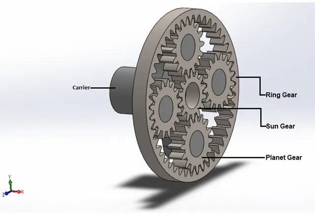
The four basic components of the Planetary gear system are:
- Sun: The central gear
- Carrier: Holds one or more peripheral Planetgears, all of the same size, meshed with the sun gear.
- Ring or Annulus: An outer ring with inward-facing teeth that mesh with the planet gear or gears.
- Carrier: The spinning platform in which gears are mounted.
Planetary gear trains provide high power density in comparison to standard parallel axis gear trains. They provide a reduction in volume, multiple kinematic combinations, purely torsional reactions, and coaxial shafting.
Disadvantages include high bearing loads, constant lubrication requirements, inaccessibility, and design complexity.
Application:
Depending on the input and output condition, the planetary gear system sometimes rotates Quickly, sometimes slowly and even in Reverse. Because of this it finds its use in Automatic Transmission in Automobile.
Calculating Pitch circle diameter of the Planet gear:
Given,
Pressure angle = 20deg,
Face Width of all gears = 12mm
Modulus of all gears (m) = 2.5,
No. of Teeth in Ring gear (Tr) = 46,
No. of Teeth in Sun gear(Ts) = 14
as, m = D/T
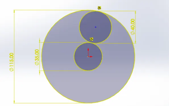
Pitch circle diameter of Ring gear (Dr) = 2.5 * 46 = 115mm
Pitch circle diameter of Sun gear (Ds) = 2.5 * 14 = 35mm
hence,
Pitch circle diameter of planet gear (Dp) = (Dr – Ds)/2 = (115-35)/2 = 40mm
Dp = 40mm.
No. of Teeth in Planet gear (Tp) = 40/2.5 = 16
Tp = 16
|
Sl. No. |
Type of Gear |
Module |
Pitch diameter(mm) |
No. of Teethe |
|
1 |
Ring |
2.5 |
115 |
46 |
|
2 |
Sun |
2.5 |
35 |
14 |
|
3 |
Planet |
2.5 |
40 |
16 |
Model and Assembly of Gears:
Running simulation on the following cases:
|
Case No. |
Input |
Output |
Fixed |
|
1 |
Sun Gear |
Carrier |
Ring Gear |
|
2 |
Ring Gear |
Carrier |
Sun Gear |
|
3 |
Sun Gear |
Ring Gear |
Carrier |
Note:
Input- Rotary Motion of 200RPM given to that part as input.
Output- After motion analysis, Angular Velocity of that part is plotted as a graph.
Fixed-Make that particular component as a fixed part.
Material provided to all gears is Steel(dry).
Motor to be applied at the central axis of the gears.
To use 1260FPS with precise.
200RPM also means 1200degree/second.
- Case 1
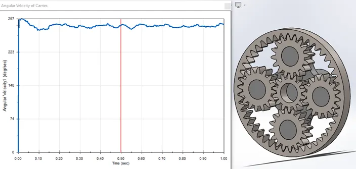
Rotary Motion of 200RPM given to Sun gear.
Fixed gear is Ring gear.
Angular Velocity plot of Carrier
Observation:
There is a reduction in output Angular Velocity in Career. This can be verified from Gear ratio formula.
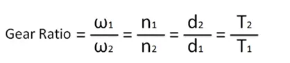
W1 = Input to Sun gear = 200RPM or 1200degree/second.
T1 =total sun gear teeth = 14
W2 =Angular velocity of career
T2 = total planet gear teeth = 4*16 = 64
i = 1200 / Angular velocity of career = 64 / 14
Angular velocity of career = 262.5.
- Case 2
Rotary Motion of 200RPM given to Ring gear.
Fixed gear is Sun gear.
Angular Velocity plot of Carrier.
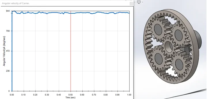
Observation:
There is a reduction in output Angular Velocity in Career. This can be verified from Gear ratio formula.
W1 = Input to Ring gear = 200RPM or 1200degree/second.
T1 =total Ring gear teeth = 46
W2 =Angular velocity of career
T2 = total planet gear teeth = 4*16 = 64
i = 1200 / Angular velocity of career = 64 / 46
Angular velocity of career = 862.5.
- Case 3
Rotary Motion of 200RPM given to Sun gear.
Fixed gear is Carrier.
Angular Velocity plot of Ring gear.
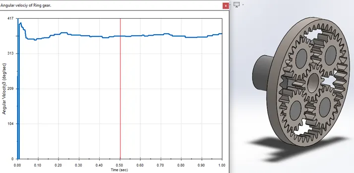
Observation:
There is a reduction in output Angular Velocity in Ring gear. This can be verified from Gear ratio formula.
W1 = Input to Sun gear = 200RPM or 1200degree/second.
T1 =total sun gear teeth = 14
W2 =Angular velocity of Ring gear.
T2 = total Ring gear teeth = 4*16 = 46
i = 1200 / Angular velocity of Ring gear = 46 / 14
Angular velocity of Ring gear = 365.22.
Conclusion:
There is reduction in output angular velocity in all the cases relative to the input angular velocity. Highest reduction in angular velocity is achieved in case 1 followed by case 3 and then case 2.
In case 1, when input is given to the Sun gear, ring gear is fixed and output is taken from carrier, the planet gears rotate around their axis and also revolve around the sun gear.
In case 2, the input is given to the Ring gear while fixed gear is sun gear. Hence the planet gears rotate around their axis as well as revolve around the sun gear. This case is similar to case1 but the angular velocity of planet in this case is more as the drive (ring gear) has higher radius. [as, V = angular velocity * Radius]. This will make planet gear spin and turn at higher speed thus carrier will turn at a higher speed.
In case 3, the drive gear is sun gear and the carrier is fixed. The planet gears rotate around their axis opposite to sun gear spin, pushing ring gear to rotate in the same direction. Thus, the direction of rotation of the ring gear will be opposite to the sun gear. [In automobile this is Reverse gear.]
Since, planetary gear system sometimes rotates Quickly, sometimes slowly and even in Reverse. Because of this it finds its application in Automatic Transmission in Automobile.