| |
1. What is the difference between the contents of Radioss Starter and Radioss Engine file in terms?
ANSWER: -
RADIOSS STARTER FILE: The starter file contains the model definition. Definitions like units, material, properties, nodal information, boundary conditions, interfaces, Load collectors, geometrical information, etc., are included in the starter file. A radioss starter input file name is runname_0000.rad and the listing file name is runname_0000.out.
RADIOSS ENGINE FILE: The engine file describes the run control. It controls the simulation speed and contains information about the software version, the run time, time history files, animation controls, etc., A radioss engine input file name is runname_0001.rad and the listing file name is runname_0001.out.
|
|
| |
2. For solid element formulations, why are the fully integrated elements (Isolid = 14) used if they are more accurate than under-integrated (Isolid = 24)?
ANSWER: -
- Isolid=14 gives more accurate results. It has fully integrated HA8 elements whereas Isolid=24 has HEPH elements with reduced integration points. It has 1 gaussian point and the hourglass control is better than Isolid=14 since it(24) has better physical stabilization. Isolid=24 is commonly used because of the lesser relative cost (1.15) whereas Isolid=14 has a higher relative cost(2.5). Isolid=14 is used mainly for its accuracy and Isolid=24 is mainly used for its elemental stabilization and relative cost.
- Multiple gaussian points are required to increase the accuracy of the stress and strain values for solid elements and hence Isolid=14 is more accurate.
|
|
| |
3. What is the difference between Engineering stress and true stress?
ANSWER: -
- True stress is defined as the load divided by the cross-sectional area of the specimen at that instant and is a true indication of the internal pressures.
- Engineering stress is defined as the load divided by the initial cross-sectional area of the specimen.
- True stress could be much larger than the engineering stress once the strain increases and the consequences, the cross-sectional of the specimen decreases.
|
|
| |
4. What is the fundamental difference between the working of a tied interface compared to the node to surface or surface to surface interfaces?
ANSWER: -
- In tied contact types, the slave nodes are constrained to move with the master surface. Both nodes are rigidly tied together. A Tie constraint will tie the selected nodes. Relative displacement between the nodes will be zero. In the tie, each slave node will have the same motion as the master.
- For both the nodes to surface and surface to surface contacts, the nodes on the slave surface interact with the master surface. Conversely, the master surface nodes do not interact with the slave surface, therefore, master surface nodes are able to pass through the slave surface.
|
|
| |
5. How to solve an issue in the simulation: Incompatible kinematic condition on a rigid wall because the slave nodes are a part of another kinematic condition
ANSWER: -
- This is a limitation of rigid walls, which is an Incompatible Kinematic Condition – a result of nodes belonging to another kinematic condition and the rigid wall.
- It is better to define the rigid wall before defining the contact interfaces.
- By removing those nodes from the slave node group.
- By applying the condition to all nodes including the master node of the rigid and try running the analysis.
- The node is defined as a slave for two parallel walls that are fixed. The node cannot impact two walls at the same time.
|
1 |
| |
6. How is the initial velocity /INIVEL different from imposed velocity /IMPVEL?
ANSWER: -
- Initial velocity is the velocity that the body has at the beginning of a given time.
- In Imposed velocity, the object has to maintain that velocity throughout the simulation.
- An object with an initial velocity, if impacted by another object, may lose energy to another object. But, the total energy in the system will remain constant at any given time. If the velocity is defined using Imposed velocity, the object has to maintain that velocity throughout the simulation.
|
|
| |
7. What are the causes for the time step change during the simulation on the elements as well in interfaces?
ANSWER: -
- In an impact simulation, the time step is calculated on the basis of the element length.
- The critical time step is calculated using the smallest element at that instant.
- An increase in the length of elements makes the time step larger and a decrease in the length makes it smaller. During the simulation, some elements may crack and some may get deleted. This may cause a change in the time step.
- If the materials in the simulation are different, then there can be changes in the time step.
Changes in stiffness, length, density, penetrations, and gap can cause changes in timestep.
|
|
| |
8. What are the 3 types of non-linearities that can arise in an analysis?
ANSWER: -
Nonlinearity means that the Stiffness matrix (K) changes with the solution, that is, it is K. A function of the nodal displacements; as K changes, a new solution must be attained until the thus iterated solution stops changing within tolerances.
- Geometric Nonlinearity: Geometrical nonlinearity means that you have to take the change of geometry into account. Basically, it is the difference between nominal stress (and strain9 and true stress (or strain). Structures whose stiffness depends on the displacement they may undergo are geometrically nonlinear. This accounts for phenomena such as the stiffening of a loaded clamped plate and buckling or ‘snap-through’ behavior in slender structures or components. Geometric nonlinearity is usually more difficult to characterize than purely material considerations. Geometric effects may be both sudden and unexpected, but without taking them into account any computational simulation may completely fail to predict the real structural behavior.
- Material Nonlinearity: Material nonlinearity is associated with the inelastic behavior of a component or system. Inelastic behavior may be characterized by a force-deformation (F-D) relationship, also known as a backbone curve, which measures strength against translational or rotational deformation. This refers to the ability of a material to exhibit a nonlinear stress-strain (constitutive) response. Elasto-plastic, crushing, and cracking are good examples, but this can also include time-dependent effects such as visco-elasticity or visco-plasticity (creep). Material nonlinearity is often characterized by a gradual weakening of the structural response as an increasing force is applied, due to some form of internal decomposition.
- Boundary condition nonlinearity/ Constraint/ ContactNonlinearity: Contact nonlinearity occurs when due to the deformation of one or more parts in contact (pushing or pulling on another) produces a deformation leading to a change in the geometry of the part that translates into a change in K or on the forces (action and reaction) between the parts in contact forcing another iteration. In highly flexible components and assemblies with multiple components, progressive displacement can cause self-contact or component-to-component contact. In such boundary condition nonlinearity, the stiffness of the structure or assembly may change when two or more parts either contact or separate from initial contact – sometimes only a little, but sometimes quite a bit. Bolted connections, toothed gears, and sealing or closing mechanisms are common examples.
|
|
| |
9. What is the role of shape function while calculating results on an element?
ANSWER: -
- The shape function is the function that interpolates the solution between the discrete values obtained at the mesh nodes.
- Discretization leads to a solution in the nodes, but no information concerning the space in between. Shape functions are required to approximate quantities between nodes, Underlying assumption of how quantities are distributed in an element (stiffness, mass, element loads; displacements, strains, stress, internal forces, etc.)
|
|
| |
10. Name any 2 methods of increasing the simulation speed.
ANSWER: -
- Multi-threading (using multiple cores of the CPU)
- Advanced Mass Scaling (AMS)
- Single precision
|
|
| |
11. For tabulated plastic material, under which conditions, an element can be failed/deleted? Name any one condition.
ANSWER: -
- Once plastic strain reaches EPS_p_max, in one integration point, the element is deleted.
- Once the largest principal strain reaches maximum tensile failure strain, the element is deleted.
|
|
| |
12. How would you model a collapsible part of a steering shaft, if the material properties of the collapsible assembly are not available? The collapsible shaft supports the steering in the steering axis but under pressure, it can hold up to 5 kN, and then it collapses. How would you model the collapsible part? Explain the approach. Drawing is optional.
ANSWER: -
Collapsible steering column: -
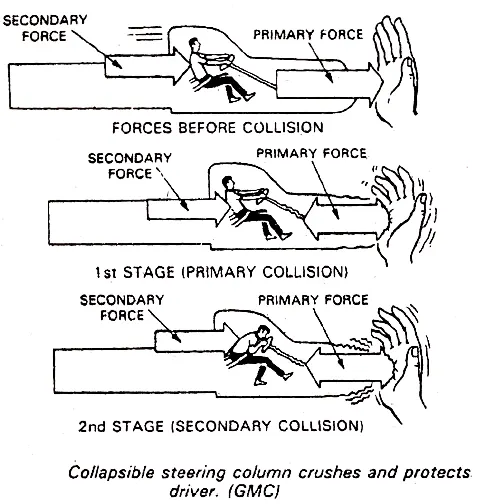
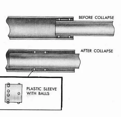
During an accident, the driver receives many injuries due to a steering column hit. A collapsible steering column prevents drivers from injury during an auto accident. When a car hits a stationary object, the engine and front body structure can be pushed rearward, into the steering column. At the same time, the driver could be thrown forward into the steering wheel. When there is a rigid steering column, the driver’s chest will injure. There are several types of collapsible steering columns. They are steel mesh (crashing) type, tube and ball (sliding) type, and shear capsule (brake and slide) type. In all types, the column is in two pieces. The two sections move toward or into each other in an accident.
- Define a material with a failure condition in /MAT/PLAS_TAB/ such that when the plastic strain reaches EPS_p_max, in one integration point, the element is deleted or when the largest principal strain reaches maximum tensile failure strain, the element is deleted. Set all the values such that when the pressure exceeds 5kN, the elements are deleted.
- Another method is to create a spring and assign values to it such that, the spring fails at a pressure greater than 5KN.
|