Fender Design Challenge
Aim: To design a half-bumper type fender from the given Class-A surface and follow the master section to create the drip area. Also, use the engineering principles to design the Sill Mount, Bumper mount and the A-Pillar Mount.
What is a Fender?
A fender is the part of a car or bike, which frames the wheel well. The primary purpose of this part is to prevent mud, rock, sand or other road sprays from being thrown into the air. Fenders are typically rigid and can be damaged by contact with the road surface. Sticky materials such as mud may adhere to the smooth outer tyre surface, while loose objects such as stones can become embedded into the tyre treads. When a vehicle moves with some velocity, these materials can be thrown out of the tyre and hit other vehicles or pedestrians. To avoid this, the fender is designed in such a way that the materials do not fly in the air and hit people in the surroundings of the car.
There are 2 types of fenders:
- Full Bumper type fender
- Half Bumper type fender
The full bumper type fender was used in the earlier days when automobiles were just about spread throughout the globe. These fenders covered the whole wheel and were bulky. Due to their shape, they also used up more materials and generated more scrap.
The half bumper type fender is common nowadays and is used in almost every car. It is smaller in size compared to the full bumper type and consumes less material for manufacturing. Also, the shape is such that, a slightly larger sheet metal blank is required than the sheet metal blank required for the full bumper type and 2 half bumper type fenders can be produced. Due to this, less amount of scrap is generated and the weight of the bumper is also reduced.
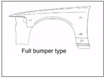
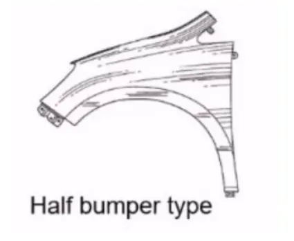
Design of the fender using NX CAD:
The Class-A surface of the fender is given as shown below:
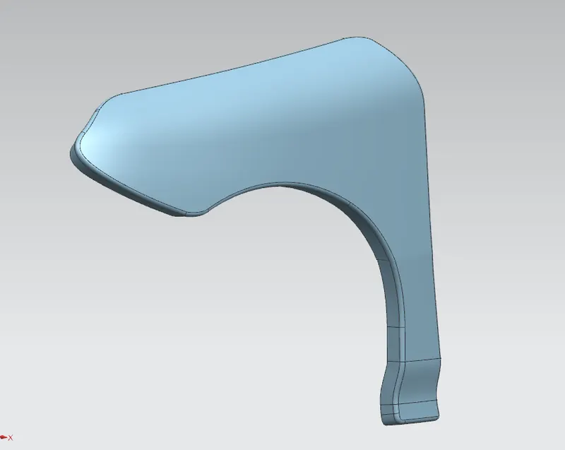
Fig. 1: Class-A surface of the fender.
The fender is mounted at a place such that it connects to multiple parts of the car. SO, while designing the fender following mountings need to be accommodated.
- A-Pillar Mounting
- Body Mounting
- Sill Mounting
- Bumper Mounting
- Drip Mounting
A master section is provided for the design of the Drip Area of the fender. The drip area is at some distance from the A-Pillar mounting and Bumper mounting as shown in the master section below:
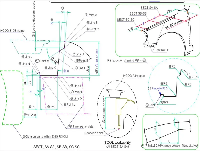
Fig. 2: Master Section for design of drip area.
Design of the A-Pillar Mounting:
The given Class-A skin of the fender has a flange running throughout its profile. Before beginning design of mountings on the fender, a few smooth curves were drawn on this flange and trimmed off to get the desired part of the flange that will be used for the creation of mounts.
The A-Pillar is the structural part of the car that connects the roof and the lower car body. Front fenders are attached to this A-Pillar to make a robust structure. This mounting was designed by using the ‘Law Extension’ command in NX CAD, by extending the flange surface and creating an embossed face with a hole in the middle as shown below. Apply the fillets to remove sharp edges.
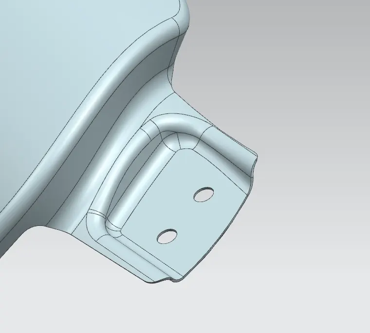
Fig. 3: A-Pillar Mounting
Design of Drip Area:
The drip area is a fender mounting attached near the engine compartment. The design is based on the master section as shown above. The placement of the drip area is such that, it has to be placed at specified distance of 150mm from the bumper mount and a distance less than the 300mm from the A-Pillar mount.
The drip area would be mounted using multiple weld nuts and a flat surface needs to be provided to fix the weld nuts. Multiple embossed faces were created as shown below. Also, the drip area is pretty long, and will undergo vibrations when the car is moving, hence a support is needed to keep the mount in place and break away from the main fender.
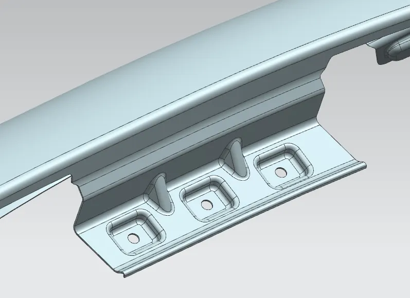
Fig. 4: Drip Area of the fender
Design of Sill Mounting Area:
Sill is the panel directly below the bottom of the door supporting the floor and may be used to combine the floor and the body. The bottom end of the fender is mounted on the sill body for the reinforcement of the fender panel. The sill mounting is designed using embossed surface and holes as shown below:
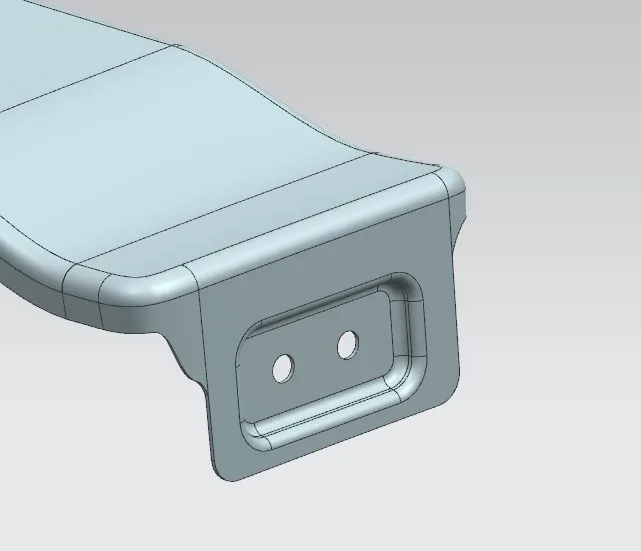
Fig. 5: Sill Mounting
Design of Bumper Mounting:
The bumper mount area is used to attach the bumper and the fender together with the help of fasteners. The drip area is also designed with respect to the bumper mount position and as per the master section.
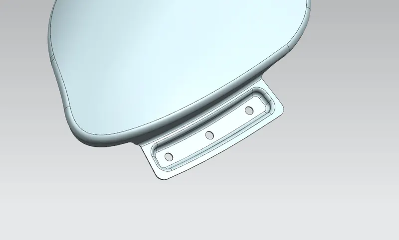
Fig. 6: Bumper Mount.
Design of Baffle Mount:
The baffles are the plastic component placed on the inner side of the fender and just outside of the tyre periphery. They are used to improve the NVH characteristics and prevent damage to the inner part of the fender.
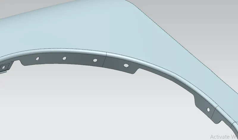
Fig. 7: Baffle Mount
After all the mounts are created using surface commands, use ‘Thicken’ option to give thickness to the sheet. Use’ Edge Blend’ to give fillets and remove sharp edges. The fender is designed as follows:
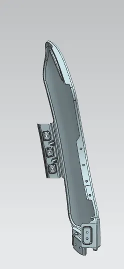
Fig. 8: Front view of Fender
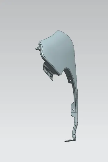
Fig. 9: Top view of Fender
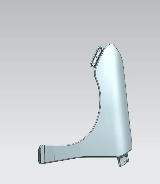
Fig. 10: Right view of Fender
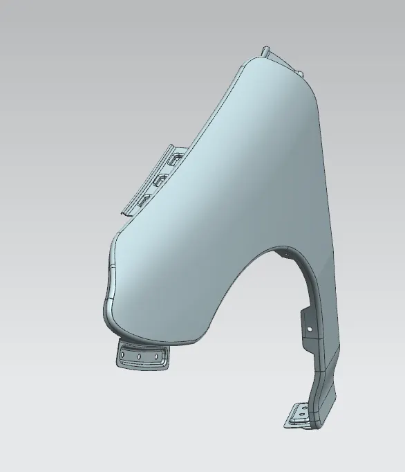
Fig. 11: Isometric view of Fender
Conclusion: The fender design was completed successfully