Fender Design
Aim:
To design Drip Area, Bumper, Baffle, Sill, and A-Pillar mount for Fender.
Procedure:
- Surface Check:
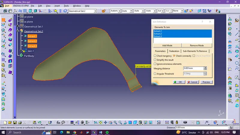
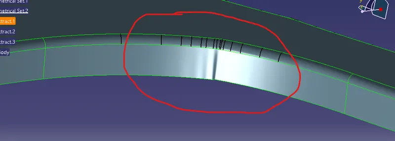
- First, we will check the surface quality by checking for surface defects or gaps between the surfaces.
- In our case our reference surface has one surface with wrinkles and one surface with a gap issue.
- To cure this issue first we will make our Class-A surface by Extracting the given Top surface and all the flange except the defective surface. (don’t extract fillet as it also gives problems)
- Now we will join all the top surfaces.
- We will get a connexity error, meaning there is no continuity in surfaces, i.e. the gap between surfaces.
- We will delete this surface and we will create our surface using the blend command.
- After creating this surface, we will join all surfaces which will make our top surface.
- We will use the same procedure as above for the flange’s bad surface but here we will use a multi-section surface instead of the blend to get more surface curvature control.
- After joining all the surfaces in the flange, we will use a shape fillet to create the fillet between the top and flange surfaces.
- We will give a 5 mm fillet so that there will not be any problem while thickening the surface.
- Now we will proceed over to drip area design.
- Drip Area Mount:
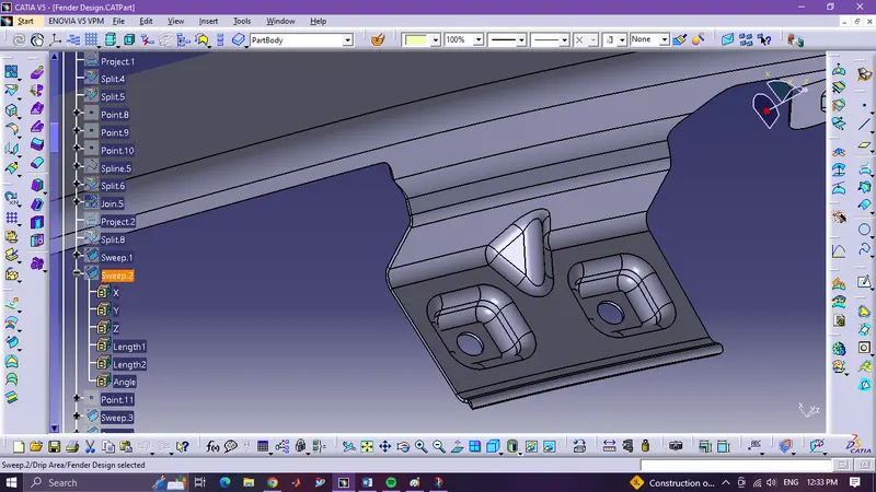
Drip Area
- First we will use the border lines of the fillet we made before as a reference line to trim the extra flange surface and offset it below by 5mm using the parallel curve command.
- As shown in the Master Section of the drip area, we need to give 200mm clearance from A-pillar and 150 mm clearance from the headlight for their mounting.
- Now we do not want sharp cut-outs so we will use a spline to give edge relief to the cut-out.
- We will split the surface with a curve to trim out the unwanted surface.
- Now to create a surface with a 45-degree angle we will use sweep with the reference surface.
- We will use sweep with draft direction and use Y Component as draft direction to create a vertical surface with a 5-degree angle.
- We will adjust the surface's length by checking the surface's distance from the top surface border, which should be under 40mm.
- Similarly, we will use a sweep with a reference surface to create a flat surface for embossing and mounting holes.
- To create emboss, we first have to create a tooling axis.
- To create a tooling axis, first, we will create a plane by the three-point method in which three points can be any of the three points on the edge of the sweep surface.
- Now we will create the line by normal to surface method in line command and we will use this plane as reference.
- After creating the tooling axis, we will offset the plane we created by 6 mm below the surface.
- Now to create a flat surface for mounting emboss we will create a rectangle in a sketch on the offset plane.
- We will create a surface in the rectangle by using the fill command.
- We will use sweep with draft direction using the tooling axis as a reference.
- Sweep should be more than 7 degrees to clear the tool properly.
- After this, we will proceed further to create other mountings.
- Sill, Baffle, Bumper, and A-Pillar mountings
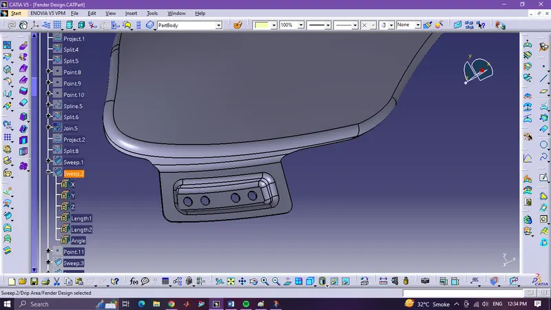
Bumper Mounting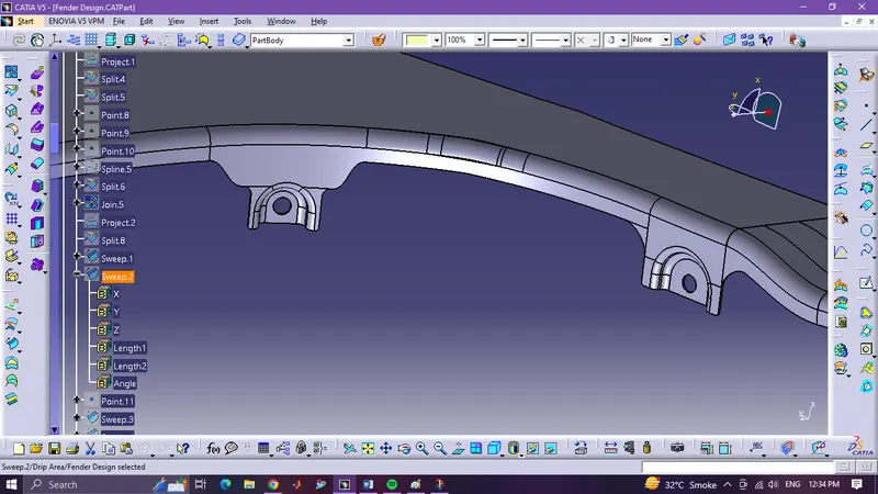
Baffle Mounting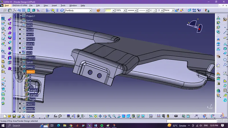
Sill Mounting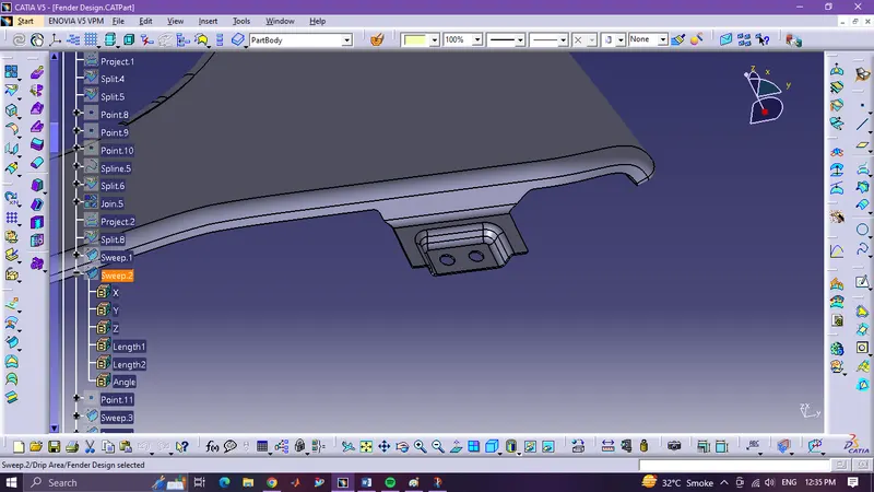
A-Piller Mounting
- Trim procedure will be the same procedure as we did for the drip area.
- After trimming, for Bumper and A-Pillar mounting, we will use a 90-degree sweep and for Sill and Baffle, we will simply extrapolate the surface.
- We will same procedure of drip area for all the mounting embosses.