Week 8 - Challenge 1 - Base Bracket Design
Aim:
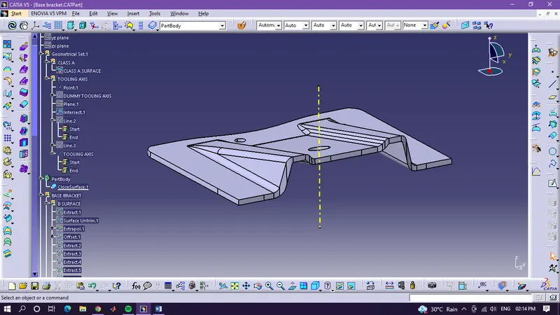
To create a tooling axis and draft analysis of Class-A surface
Objective:
To check whether all the surfaces in Class-A have 3 degrees or more than 3 degrees so that they can easily be ejected from the mold.
Procedure:
- To create a draft analysis, first, we need to create a tooling axis.
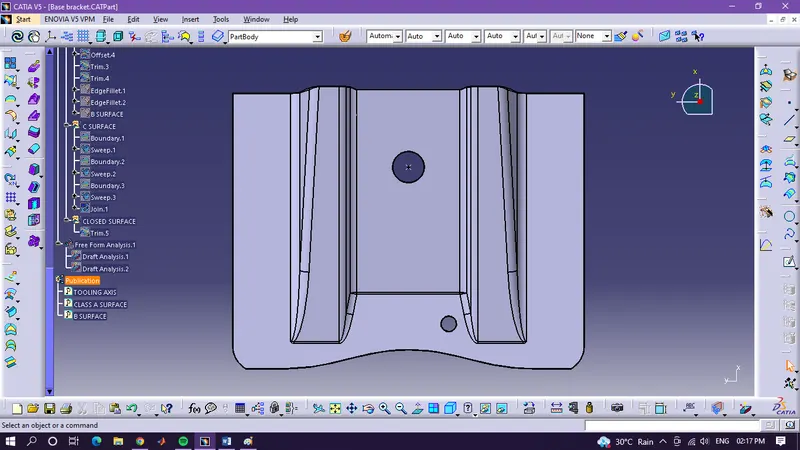
- First we will create a point in the center of the top hole of the Class-A surface by using the ‘Circle / Sphere / Ellipse center’ method in the ‘point’ option.
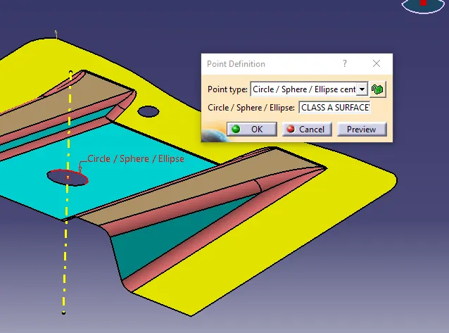
- After creating a point, we will create a line that will go through the center of the hole by using the ‘Point-Direction’ option in the ‘line’ command.
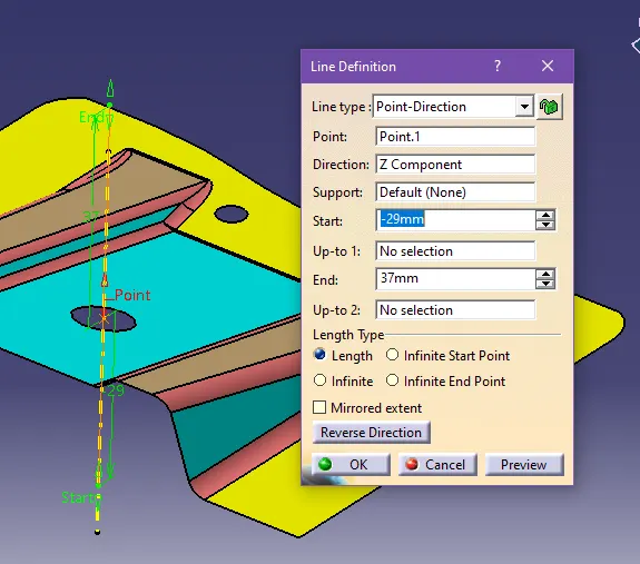
- This line will be a dummy tooling axis.
- Now we will check the problematic surfaces on all axis that can be less than the required draft angle and also create the tooling axis.
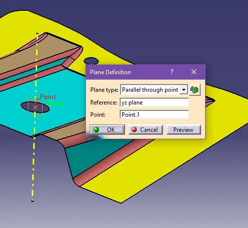
- In our case, these surfaces are only at the y-axis so ye will use the yz plane as a reference.
- Now we will create a plain at the point that we created earlier by using ‘Parallel through the point’ in the ‘plane’ command and will use the yz plane as reference.
- Now we will use intersect command to create a line concerning the yz plane and Class-A surface.
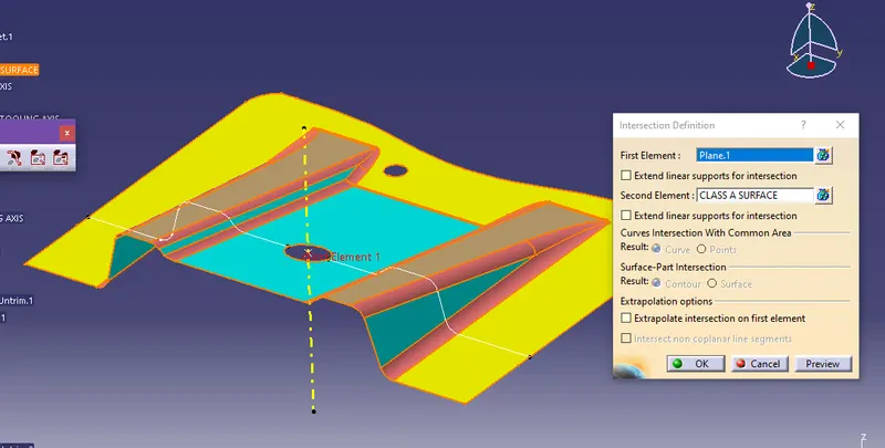
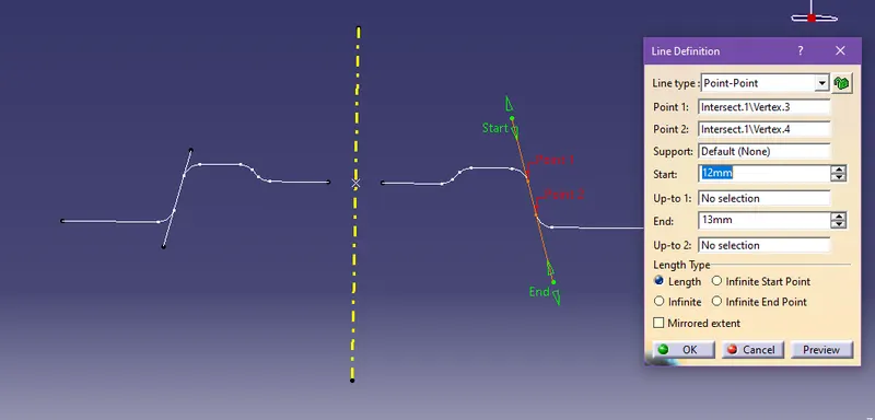
- With the help of these lines we will extend the lines of problematic surface lines by using the ‘Point-Point’ method in the ‘line’ command and take the endpoints of the existing lines.
- Now we will create the tooling axis by the bisecting method which is in line command and bisect two lines that we extended previously to create a line between them.
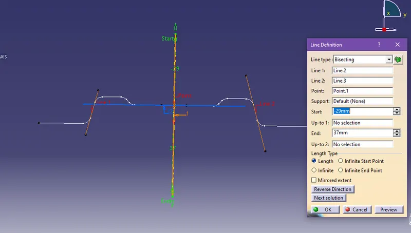
- We will change the color and line type of the tooling axis line to highlight it and publish it.
- To publish the line and also the Class-A surface, go to tools – publish, and a dialog box will appear.
- Now select the features to be published and click ok.
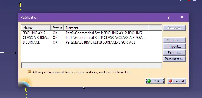
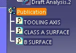
- Your parts will be published.
- Now to create a draft analysis, first change the view parameter to custom then make sure ‘material’ is selected in the mesh section.
- Now go to insert – analysis – Feature Draft Analysis, two dialog boxes will open. One will be color notations and the other one will be options.
- First we will drag the compass which is on the right corner of the screen to the tooling axis line.
- Then we will select the surface on which we want to create a draft analysis.
- We will set the draft limit to 3° on the color notation window.
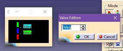
- Now click ok to complete the draft analysis.
- The upper side of the surface should be a green color which means the surface is more than 3°. If not then it will be either blue which is between 3° and 0or red which means less than 0°.
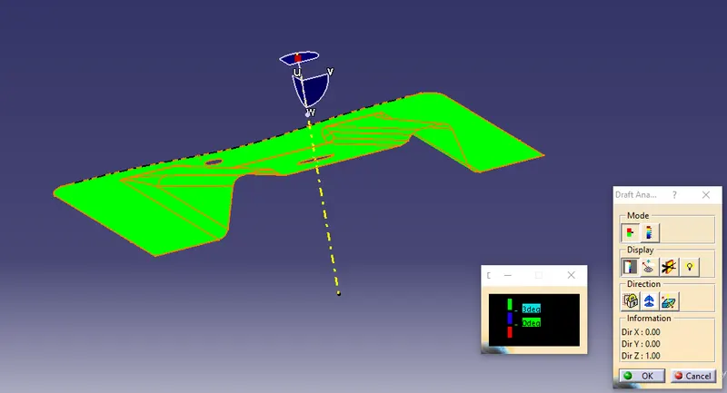
- If the surface is not passing the test, then we have to either change the tooling axis direction or modify the surface.
- If the test passes, then we can proceed to the next step.
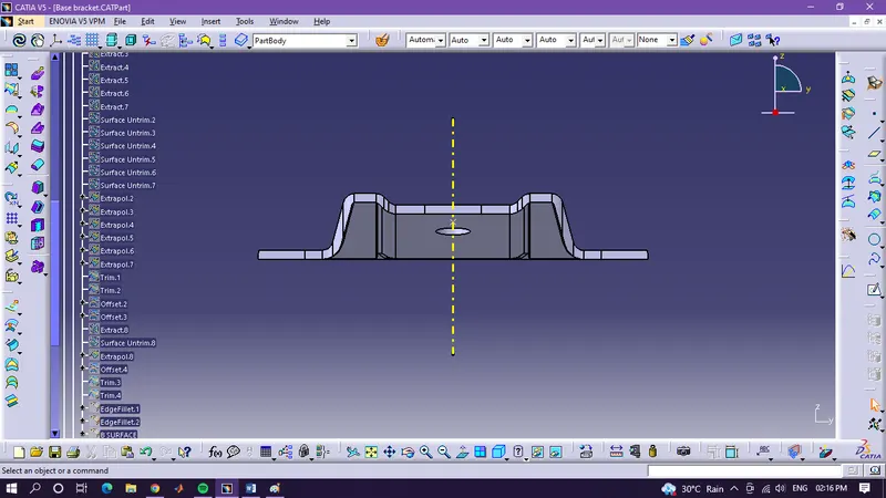
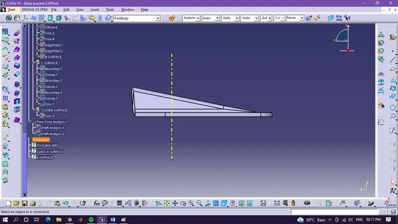
Below are the screen-shots of the final product: