Fender Design - Wheel Arch Challenge
Aim: To Calculate the Wheel Arch gap at required points and to check whether the car passes the European standard.
Wheel Arch Design:
In wheel arch design, there are two main design criteria,
- While driving dirt and dust coming from rotating tires should not come out of the wheel arch and above.
- Wheel should not stick out of the fender for pedestrian safety reasons.
There are different clearances applied in different regions to satisfy their road and environmental conditions.
Japanese Wheel Arch design standard:
Following are the design criteria that must be filled in to pass the pedestrian safety test in japan.
- Measure the clearance of ‘L’ of the tire, hub, cap, and fender in three different positions within area ‘K’ and produce a clearance check chart to validate the results.
- Clearance must be greater than 5mm in all the three positions
- Wheel guard requirement: The value ‘a’ shall be more than 5 mm at a line 30 degrees forward and 50degree rearward from the central vertical axis of the wheel.
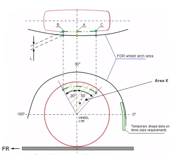
Japanese Wheel Arch Design Diagram
European Wheel Arch design standard:
Following are the design criteria that must be filled in to pass the pedestrian safety test in japan.
- Measure ‘CL’ and ‘L’ in the section ‘SA-SA’ ‘SB-SB’ ‘SC-SC’ ‘SD-SD’ ‘SE-SE’ and produce a CL check chart to validate.
- At all five sections the ‘CL’ ‘L’ value should be greater than 10mm to satisfy the European regulation.
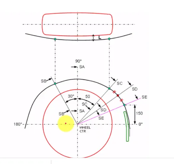
European Wheel Arch Design Diagram
Procedure:
- To Start plotting points, first we will create a plane on the outermost surface of the tire by using the offset option in the plane command.
- Then we will create a point in the center of the wheel by using the circle center option in the print command.
- Now we will create a sketch on the plane we created to make Sections SA, SB, SC, SD, and SE.
- First we will create the horizontal line that goes through the tire’s center for reference.
- Now we will create a 90-degree line which will be our section ‘SA-SA’.
- We will create two lines, one at the front side of section SA and one at the rear.
- The front line will be section SB which will be 30 degrees from section SA.
- The rear line will be Section SC which will be 50 degrees from section SA.
- Now we will create one more line just below Section SC which will be our section SE.
- Now we will project the line of fender two intersect all these lines.
- After projection, we will create points by the intersection method which will intersect between all sections and the fender line.
- After creating all the points, we will, measure the SE point from the rear end of the fender arch and change it to 150mm.
- After this we will create one more section which will come in between ‘SC-SC’ and ‘SE-SE’ by bisection method.
- We will plot this point which will be the SD section.
- Now we will complete the sketch and we will project all these points on the fender arch.
- After projecting all the points, we will measure the distance between the original and projected points.
- If the projected point is behind the original then the measurement will be positive, or else the measurement will be negative.
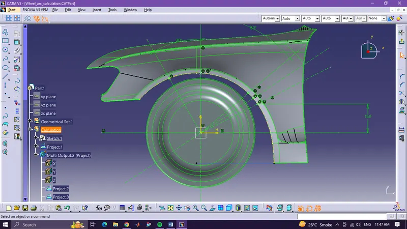
Sketch Screen Shot
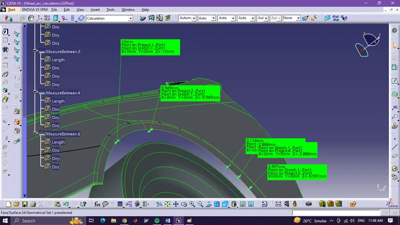
Measurement Screen Shot
|
SB-SB |
SA-SA |
SC-SC |
SD-SD |
SE-SE |
|
|
Required |
10mm |
10mm |
10mm |
10mm |
10mm |
|
Measured |
10mm |
9.949mm |
-0.114mm |
-2.888mm |
-5.997mm |
Conclusion: The following data shows that the clearances at sections SA and SB are in the standard range but the clearances at sections SC, SD, and SE are not in the standard range. Also, the tire is coming out of the fender arch which is not safe for pedestrians. This concludes that the given fender design is unsafe per European standards.