Roof Design
Aim: To create an assembly by developing the essential flanges for the outer roof and creating the reinforcements.
Procedure:
- For all the roof components, we will use stamping operations to produce those parts.
- For this reason, we will start the design process of all parts by creating a tooling axis.
Roof Outer Panel:
- As we do not have the tooling axis of the given roof outer surface, we will create our roof outer by only taking the roof surface as a reference. (we will take only one-half of the roof as we will mirror it later.)
- We will extract this surface and then we will create a tooling axis by using the normal to surface option in the line command.
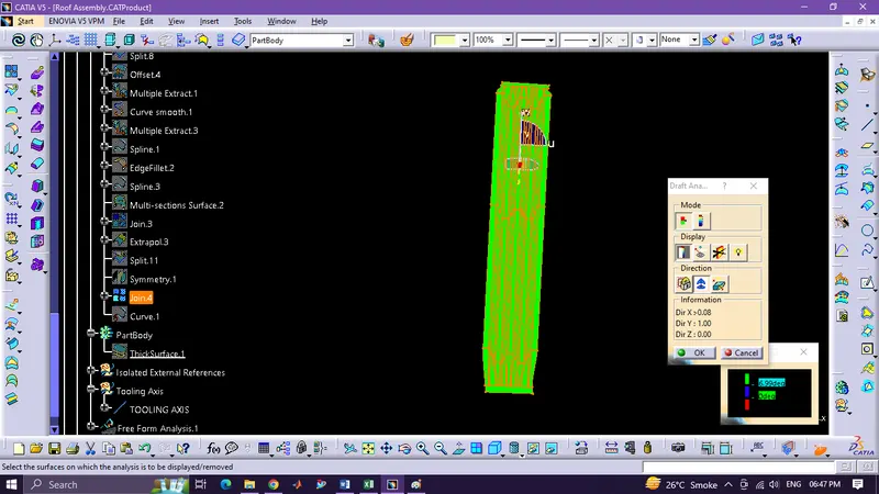
- After creating the tooling axis, we will start making the ditch area by using the sweep command using the tooling axis as the draft direction.
- We will create a sweep at a 7-degree angle from the tooling axis for about 20mm.
- We will create this sweep in front and side only.
- Now we will offset the main roof surface in the downward direction by 17 mm.
- We will trim the flange with an offset surface to create the front ditch area.
- For the rear ditch area, we will need to design it to clear the back door when opened.
- To do that we will make a flange by sweep command as given in the master section.
- After that we will offset the main surface in the downward direction up to the specified dimension given in the mater section and trim it.
- After that we will create a flange for rubber sealant.
- Then we will give a cut-out for the clearance of C-Pillar.
- We will give fillets to all the sharp edges to reduce stress concentration.
Front Roof rail:
- First we will extract the roof surface and front flange surface.
- Now we will offset the roof surface by 32mm downward.
- Now we will offset the flange by 80 mm in an inward direction to the extracted surface as specified in the master section.
- We will trim both surfaces to create the rear side of the flange.
- We will create the tooling axis normal to the horizontal flat surface.
- After creating the tooling axis, we will create a sweep for the front flange concerning the draft angle of more than 7 mm.
- Now we will extract the front ditch flange and offset it by 7 mm to create the flange for the roof rail which will be spot welded together.
- We will trim this offset to the sweep we created to create the emboss at the front.
- Backside of the flange will be attached by the mastic paste, so we have to give a 5 mm gap for the mastic clearance.
- We will offset the roof surface 2 times for two embosses, one at 6.5 mm and the other at 4.5 mm.
- We will join all of these surfaces by trimming them and creating a sweep in between them.
- Now we will trim the outside edge to give clearance for A-pillar.
Rear Roof Rail:
- Once again we will extract the roof surface and also the rear lower ditch flange.
- Now we will offset the rear ditch flange by 10.7 mm downward.
- We will extrapolate this surface and then create a tooling axis normal to this surface.
- Now we will create a flange at the rear which will be used to join the rear roof rail by spot welding.
- Now at the front side first we will trim the surface to 90mm and then create a sweep at 32 degrees concerning draft direction.
- The other side of the rail will be attached by mastic past so we will use the same procedure as we did previously in the front flange.
Center Roof Rail:
- First we will extract roof surface the roof surface which we will use for embosses.
- Now we will create center planes on the center edge by using normal to curve in plane command.
- First we will create multiple planes by using the offset planes option in the plane command.
- We will give 7.5 mm from both sides for the center flange and 10 mm for lower flanges and 15mm for the outer flange for mastic and we will give 5 mm distance in between flanges.
- We will offset 3 surfaces from the roof extract for measurements given in the master section.
- We will split all the surfaces with the plane we created earlier.
- Now we will create blends in between every flange without giving tangency to any surface.
- We will give all edges a fillet.
- To create the flange for spot welding, we will extract the side ditch flange and split a part of it.
- Now will split the rail in an inward direction to create a multi-extract between the rail and the flange we trimmed earlier.
- We will create a multi-extract between the flange and rail and we will join them together.
Bow Roof Rails:
- For the Bow roof rail we will simply copy past the center roof rail as both designs are the same and place it between the front roof rail and center roof rail, center roof rail, and rear roof rail.
- As given in the master section, we will reduce the size of the bow roofs we copied recently by readjusting the planes we created in the center roof rail.
Heat Distortion Calculation:
Formula: W = [1.73 x 10^(-3) x L] + [1.85 x 10^(-8) x (R^2)/t] + [ 1.10x10^(-3) x l] - 2.68
Where,
L = Roof Length in X-Direction[mm](Roof dimension in 0-Y)
R = Roof curvature
R = 2(Rx*Ry)/(Rx+Ry)
Rx = X curvature
Ry = Y curvature
t = Roof plate thickness [mm]
l = Bow Roof Span [mm]
Procedure:
- After thickening every part, we will convert the assembly product to a CATpart in a different window to work on the model.
- Now we will create an excel sheet where we can register all our data for different cases and calculations.
- Now in catia we will create a sketch in the zx plane to calculate data.
- We will do the calculation for the first case which is between the front roof rail and the bow roof one.
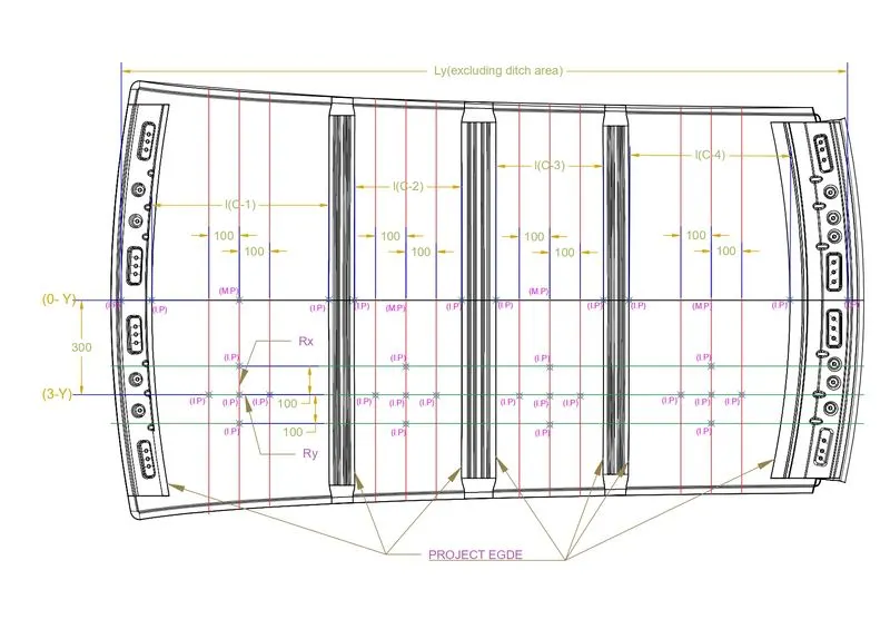
- We will project in the boundary of both roof rails and create a horizontal line that goes through the center of the roof.
- Now we will plot points between the plotted line and the horizontal line.
- Now we will create a vertical line that will go through the middle of two plotted points.
- On this line, we will create a horizontal line 300 mm away from the center on any side and make a 100 mm offset of the same line in both directions.
- We will create the same 100mm offset for the vertical line too.
- Now we will plot the points in the following intersection shown in the diagram below.
- Now we will come out of the sketch and we will project all the plotted points on the roof surface.
- After projecting all the points, we will create two arcs in X and Y directions as shown in the diagram.
- This will give the value of Rx and Ry for the above formula.
- We will take these two and other values given above in the formula and calculate the value of heat distortion at that region.
- We will follow the same procedure for other cases too.
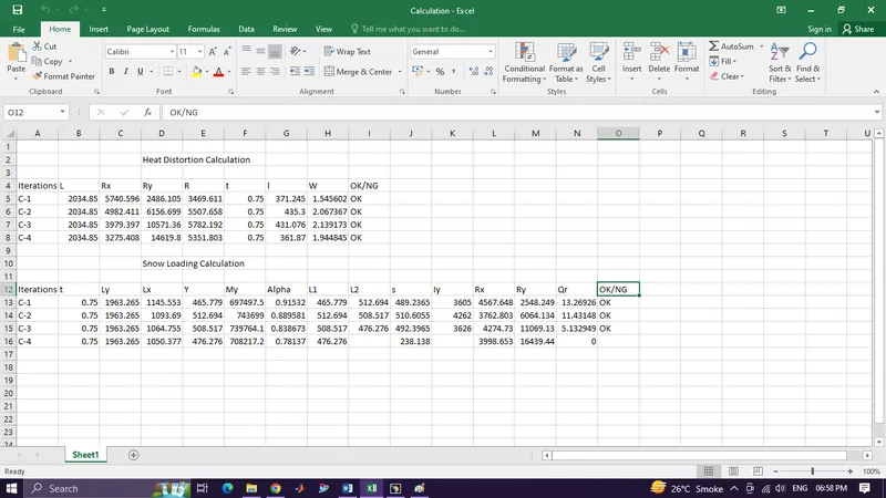
- Value of W should not exceed 2.7 value.
Snow Loading Prediction:
Formula: Qr = [Iy x t2] / [α x s x [(Rx + Ry)/2]2 x 10-8]
Where,
α = My x Lx2 x 10-12 , My = Y(Ly-Y)
t = Roof plate thickness [mm]
Ly = Distance between the front and rear roof Rails on the Vehicle along with 0Y[mm]
Length of Roof panel with the center point between Roof Rail Front /Rear as the front and rear reference point.
Lx = Distance between the Left and Right end of the roof on the Roof BOW [mm]
The width of the roof panel is exposed on the surface.
Y = Distance front Roof Rail to Roof BOW[mm]
s = Distance for which Roof BOW bears divided load [mm]
s = L1/2 + L2/2
Iy = Geometrical moment of inertia of Roof BOW (Y cross-section)[mm4]
Rx = Lateral direction curvature radius of roof panel Y cross-section on Roof BOW [mm]
Roof panel curvature Radius of the Length Lx in Front view
Ry = Longitudinal Direction curvature radius of the Roof Panel X cross-section on Roof BOW [mm]
Roof panel X curvature radius of length s in Side view
Procedure:
- In this calculation we will use the same part file which we used for the above calculation.
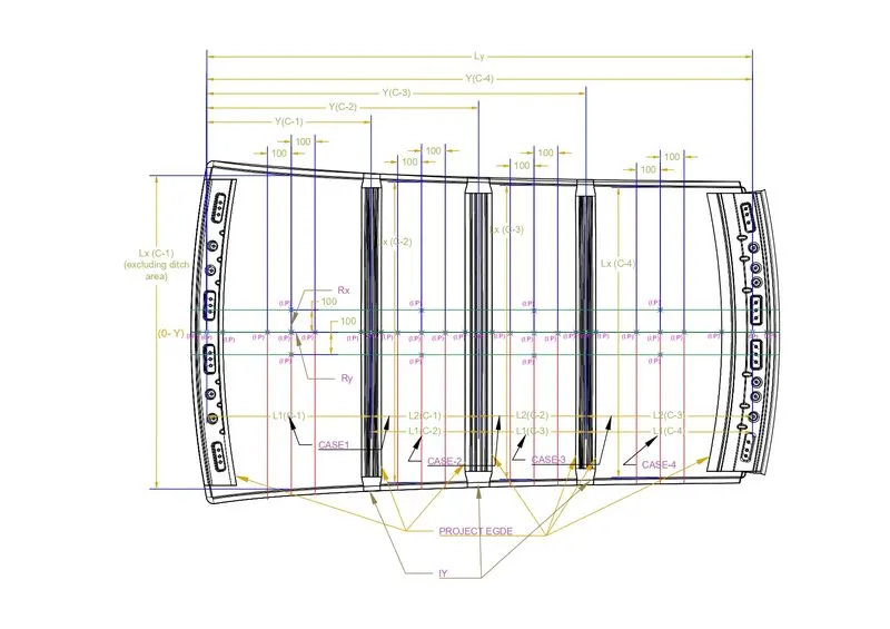
- We will create a sketch and similarly to what we did above, we will create a horizontal line through the center of the roof.
- Here we will project both sides of the borders of the roof rails for 1st
- Now we will create center points in both roof rails.
- Also we will create a vertical line between both roof rails.
- We will offset this vertical line by 100 mm on both sides.
- We will do the same for the horizontal center line.
- Now we will plot points at the intersection as given in the diagram below.
- Now we will measure all the data we need for the above formula and we will exit the sketch.
- We will project all the points on the roof surface and create the circle in X and Y directions.
- We will measure Rx and Ry values through this curve.
- We will register all the data we got in the same excel sheet we created for heat distortion calculation and apply it to the given formula.
- Value of Qr should be less than 3.1.
Calculations:
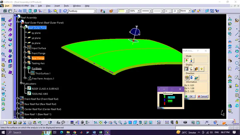
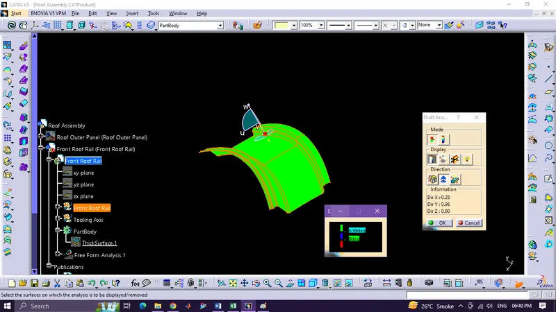
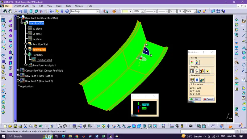
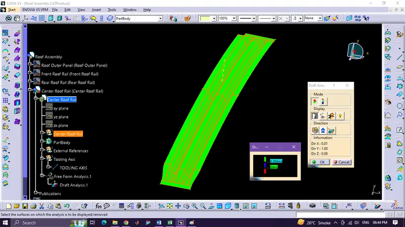
Draft Analysis:
- Roof:
- Front Roof Rail:
- Rear Roof Rail:
- Center Roof Rail:
- Bow Roof Rail 1:
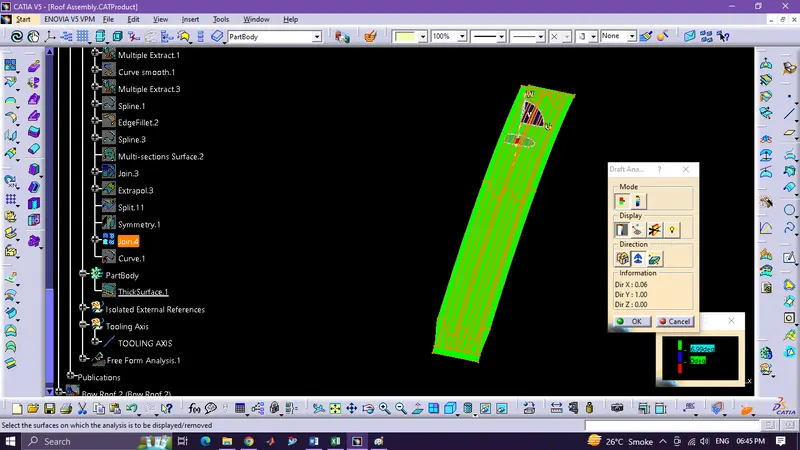
- Bow Roof Rail 2: