Drafting of various geometries using Chamfer, Fillet tool in AutoCad
AIM To Draw the given geometric diagram in AutoCAD with different units of measurement
Introduction
Types of units measurement in AutoCAD:-
AutoCAD is extreamely flexible about drawing units, let us have them in our way AutoCAD's Length unit types are as Follows
- DECIMAL UNITS:The decimal units can be represented as an inch, meter, millimeter, or any other unit.
- ENGINEERING UNNITS:The engineering units are like architectural units, but they represent the feet and inches in the format of the decimal. For example, 4'5.5000".
- ARCHITECTURE UNITS: The architectural units are based on the feet and inches. It uses fractions to represents the partial inches. It displays feet and inches in the format of decimals and fractions. For example, 4'- 5 1/2".
Here, single quotes (') signifies feet and double quotes (") signifies inches. - FRACTIONAL UNITS : The fractional units are the unitless decimal units, which display the value in fractions rather than decimals. For example, 5/2.
It also represents whole numbers or whole numbers with fractions. For example, 5 ½. - SCIENTIFIC UNITS : The scientific units are used to display the units in the form of the decimal value raised to a power. It displays the value of exponents. For example, 2.600E + 04. It is used to display large values.
AIM : To Draw the given geometric diagram in AutoCAD by using Decimal
Procedure
Step 1 :
- Open AutoCAD software click on WIZARD the advanced settings and set the units as Desimal
- Set the angle in degree with base angle as east and mark the angle direction in counterclockwise
- In the command box,type UNIT and select the decimal unit
- Now type L for for line comman and press enter
- Specify the starting point of line as (1,1) in the command box and press enter.
- Specify the next point of line as (@3,0) in the command box and press enter.
- Specify the starting point of line as (@2.12< 45) in the command box and press enter.
- Specify the starting point of line as (@2.83<135) in the command box and press enter.
- Specify the starting point of line as (@-2,0) in the command box and press enter.
- Then click on close option from the command box and press enter to cancel the line command
Step 2 :
- Select circle tool from the ribbon tab
- Select Center,diameter from the drop-down list
- Enter the center point as (2.5,2) and press enter
- Specify the diameter as (1,2) and press enter
- Again select the circle tool from the ribbon tab
- Select Center Diameter from the drop-down
- Enter the center point as (2.5,3.5) and press enter
- Specify the diameter as 0,8 and press enter
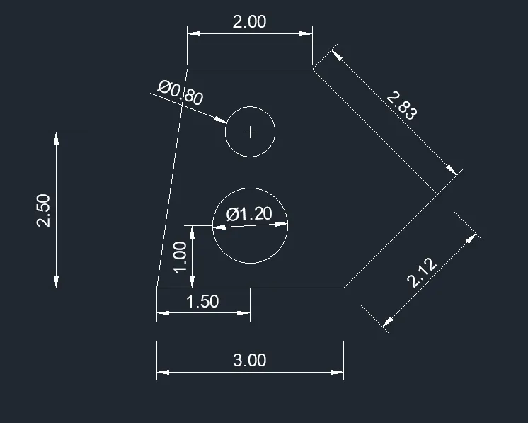
RESULT :The given geometric diagram is drawn in AutoCAD by using decimal
2) AIM To Draw the given geometric diagram in AutoCAD using Architectural units
PROCEDURE
Step 1 :
- Open AutoCAD software click on WIZARD the advanced settings and set the units as Architectural
- Set the angle in degree with base angle as east and mark the angle direction in counterclockwise
- Type units in command box and press enter
- Select the type as Architectural
- Keep the units as feet
- Now, type L for line command and press enter specify the starting point of line as(1,1) and press enter
- Specify the next point as (@3'<135) in command box and press enter
- Specify the next point as (@2'5''<90) in command box and press enter
- Specify the next point as (@8'<0) in command box and press enter
- Specify the next point as (@1'9''<270) in command box and press enter
- Specify the next point as (@2'10''<225) in command box and press enter
- press esc
- Select the line tool from the ribbon tab
- specify the starting point as (1,1) in the command box and press enter
- Specify the next point as (@2'6''<45) in command box and press enter
- Type L for line command and join the ends of the line to close the geometry
- Press esc
Step 2 :
- Type dimstyle in the command box and press enter
- From the Modify Dimension style tab select primary units
- Select the unit format as Architectural and click OK
- Then specify the dimensions in the geometry
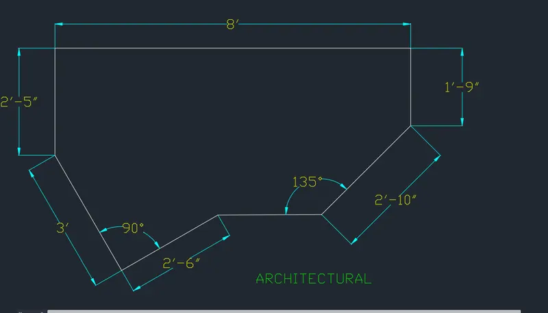
RESULT :The given geometric diagram is drawn in AutoCAD by using ARCHITECTURAL units
3) AIM To Draw the given geometric diagram in AutoCAD using ENGINEERING units
PROCEDURE
Step 1 :
- Open AutoCAD software click on WIZARD the advanced settings and set the units as engineering
- Set the angle in degree with base angle as east and mark the angle direction in counterclockwise
- Select the line tool from the ribbon tab
- Type L for line command and press enter and specify the starting point at (4,4) in the command box and press enter
- Specify the next point as ( @2'6.5<180) in the command box and press enter
- Specify the next point as ( @3'3<270) in the command box and press enter
- Specify the next point as ( @5'0.1''<0) in the command box and press enter
- Specify the next point as ( @1'6''<90) in the command box and press enter
- Click on the close option from the command box and press enter to cancel the line command
Step 2:
- Select the circle tool from the ribbon tab
- Select center diameter from the drop-down
- Enter the center point as (2'8.5'',2'3'') and press enter
- Specify the diameter as (1'6'') and press enter
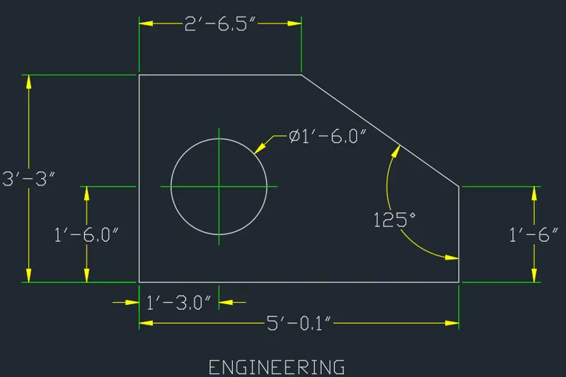
RESULT :The given geometric diagram is drawn in AutoCAD by using ENGINEERING units
4) AIM To Draw the given geometric diagram in AutoCAD using DECIMAL units
PROCEDURE:
-
Open AutoCAD software click on WIZARD the advanced settings and set the units as decimal with pression 0.00 keeping ortho on
-
Set the angle in degree with base angle as east and mark the angle direction in counterclockwise
- Type L in line command and press enter
- Speecify the Starting point as (1,4) in the command box and press enter
- Specify the next point as (@0,-3) in the command box and press enter
- Specify the next point as (@3,0) in the command box and press enter
- Specify the next point as (@0,-0.5) in the command box and press enter
- Specify the next point as (@2.5,0) in the command box and press enter
- Specify the next point as (@0,2.5) in the command box and press enter
- Specify the next point as (@-2,0) in the command box and press enter
- Specify the next point as (@0,3) in the command box and press enter
- Specify the next point as (@-2.5,0) in the command box and press enter
- Specify the next point as (@0,-2) in the command box and press enter
- Click on the close option from the command box and press enter to cancel the line command
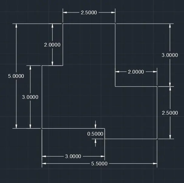
RESULT :The given geometric diagram is drawn in AutoCAD by using DECIMAL units
5) AIM To Draw the given geometric diagram in AutoCAD using DECIMAL units
PROCEDURE
Step 1 :
- Open AutoCAD software click on WIZARD the advanced settings and set the units as decimal with pression 0.00 keeping ortho on
-
Set the angle in degree with base angle as east and mark the angle direction in counterclockwise
- Type REC for rectangle and press enter
- Specify the starting points as(1,1) and press enter
- Select Dimensions in the command box
- Give length as 11.5 and press enter
- Give width as 6 and press enter
- Take the cursor to +X and +Y coordinates
- use EXPLODE command to break the rectangle into command objects
Step 2 :
- Select the line tool and draw the lengths starting from the base of 11.50 units
- Give line command @6<90 , @11.50<180, and close
- Draw the vertical lines at 2.75 from the center of the rectangle on base sides
- Draw concentric circles with center at X=1.50 and Y=3.00 of diameter 1.00 and 2.00
- Copy the corcles towords 4.25 roght from the rectangle
- Draw another circle at center of the rectangle of diameter 3.00
- Annotate and give dimension to all the line segments and circles
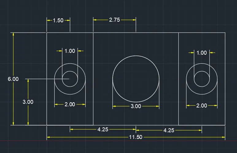
RESULT :The given geometric diagram is drawn in AutoCAD by using DECIMAL units
6)AIM To Draw the given geometric diagram in AutoCAD using DECIMAL units
PROCEDURE
Step 1 :
- Open AutoCAD software click on WIZARD the advanced settings and set the units as decimal with pression 0.00 keeping ortho on
- Set the angle in degree with base angle as east and mark the angle direction in counterclockwise
- Using line command: Draw 1.5 unit horizontal and vertical on both sides
- Using offset command: Offset 1.5 unit line to 0.5 unit
- Using divide command: Divide 1.5 unit into 3 segments
- Using line command: Join the divide lines
- Keep the extension on object snap setting
- Using line command: Draw 2 unit line and 1.5 unit line and 0.5 unit horizontal on top and in vertical 0.5 unit on bottom and jpin the slant height
- For the top figure using the line command 2 unit horizontal and 1.5 unit vertical on both sides
- Using Offset command: offset 1.5 unit line to 0.5 unit
- Using divide command: divide 1.5 unit into 3 segments
- Using line command: join the divide lines
Step 2 :
- Press F8 to on the ortho mode
- Type CO in command box for copy
- Select the right vertical line of 1,5 unit length to copy
- Select bottom end of the line as base point
- Keep the cursor in left direction and type 3.5 and press enter
- Type L for line command andpress enter
- Select top end of the copied lines as a starting point and specify the next point as (@-1.5,0) in the command box and press enter
- Specify the next point as (@0,-1.5) in the command box and press enter
- Specify the next point as (@1.5,0) in the command box and press enter
- Press enter to escape line command
- Type O and press enter to activate offset command
- Enter the offset distance as 0.5
- Select the copied line and offset the line 2 times in negative x-direction
- use trim command to trim the extra lines and press ESC
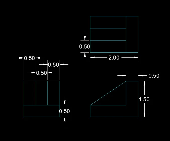
RESULT :The given geometric diagram is drawn in AutoCAD by using DECIMAL units
7) AIM To Draw the given geometric diagram in AutoCAD
PROCEDURE
Step 1 :
- Open AutoCAD software click on WIZARD the advanced settings and set the units as decimal with pression 0.00 keeping ortho on
- Set the angle in degree with base angle as east and mark the angle direction in counterclockwise
- Type L for line command and press enter
- Specify the starting point (1,1) and next point as (@0,100) , ( @210,0) , (@0,75) in command box
- Press enter to cancel line command
- Type fillet command in command box and press enter
- Give fillet radius 15 and press enter , select first and second line to fillet the joining vertice at a radius of 15 unit
- Again select second and third lines to filet the joining vertice at a radius of 15 unit
- Press ESC
Step 2 :
- Type L for line command and press enter
- Specify the starting point as (71,1) and next point as ( @0,40) , ( @90,0) , ( @0,-15) in the command promt
- Press enter to end line command
- Type fillet comand inthe command box and press enter
- Give fillet radius 20 and press enter
- Select first and second lines drawn in this step and press enter then press ESC
- Type fillet command in the command box box give fillet radius 6 and press enter select second and third lines drawn in this step and press enter then press ESC
Step 3 :
- Select the Circle tool from the ribbon tab
- From the drop-down list select the center diameter and specify the center point as (36,0) and press enter
- Specify the diameter as 50 and press enter again select the circle tool from the ribbon tab
- From the drop-down list select Center Diameter and specify the center point as (186,26) and press enter
- Now Specify the diameter as 30 and press enter
Step 4 :
- Select Arc from the ribbon tab from the drop-down list, select start,end,radius
- specify the start point as (1,1) and end point as (36,1)
- Enter radius as 35 in the command prompt and press enter
- Again select Arc from the ribbon tab From the drop down list, select start,end,radius
- Specify the start point as (161,41) and end point as (211,41) and enter the radius as 25 in the command prompt and press enter
- Select Rectangle from ribbon tab
- Specify the first corner as (21,61) in the command prompt and select dimensions from command prompt
- ENter the length as 70 and width as 30 press ESC
- Again select rectangle from the ribbon tab specify the first corner as (121,61) in the command prompt and slect the dimensions from the command prompt
- Enter the length as 70 and width as 30 press ESC
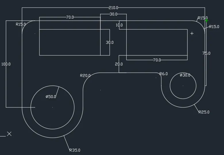
RESULT :The given geometric diagram is drawn in AutoCAD by using DECIMAL units
8) AIM To Draw the given geometric diagram in AutoCAD
PROCEDURE
- Open AutoCAD software click on WIZARD the advanced settings and set the units as decimal with pression 0.00 keeping ortho on
- Set the angle in degree with base angle as east and mark the angle direction in counterclockwise
- Using circle command: Draw concentric circles of diameter 5 units and 4 units
- Using Line command : From the center point of the circle draw 4.275 line on both sides
- Using circle command: Draw a circle of diameter 0.90 units on both sides
- Using Arc command: From the start, end and radius draw an arc of radius 0.90 units on both sides
- Using command line join the lines to the arc
- By using trim command trim the extra lines left
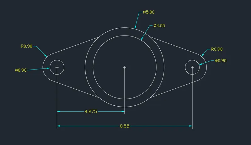
RESULT :The given geometric diagram is drawn in AutoCAD by using DECIMAL units
9) AIM To Draw the given geometric diagram in AutoCAD
PROCEDURE
- Open AutoCAD software click on WIZARD the advanced settings and set the units as decimal with pression 0.00 keeping ortho on
- Set the angle in degree with base angle as east and mark the angle direction in counterclockwise
- Using line command draw a 32'6'' horizontal line
- Using circle command: Draw a circle of radius 8' on left side of line and radius of 9' on right side of the line
- Using Arc command: From start,end,and radius draw a aArc of 41'8'' on top and 20'10'' on bottom
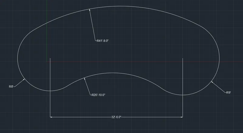
RESULT :The given geometric diagram is drawn in AutoCAD
10) AIM To Draw the given geometric diagram in AutoCAD
PROCEDURE
Step 1 :
- Open AutoCAD software click on WIZARD the advanced settings and set the units as decimal with pression 0.00 keeping ortho on
- Set the angle in degree with base angle as east and mark the angle direction in counterclockwise
- Type Rec in Command box and specify the first point(1,1) and click on dimension option and specify length as 5 unit and width as 5 unit
- Now type O for offset and specify distance as 0.2 and select rectangle and click out side the rectangle to draw offset
Step 2 :
- Select the whole objects and type co for copy , specify the base point and copy it
- use ro command to rotate the copied object at an angle of 45 degrees
- use MO command to move the copied object at the disired place
- use trim command to trim the extra lines
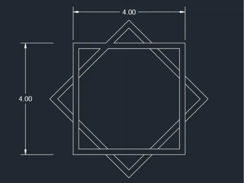
RESULT :The given geometric diagram is drawn in AutoCAD
11) AIM To Draw the given geometric diagram in AutoCAD
PROCEDURE
- Open AutoCAD software click on WIZARD the advanced settings and set the units as decimal with pression 0.00 keeping ortho on
- Set the angle in degree with base angle as east and mark the angle direction in counterclockwise
- Using line command: Draw 10'2'' horizontal line , 9' vertical line and 3' horizontal line , 4'6'' vertical and hortizontal line and 12'' vertical line
- Using mirror command: Mirror the above lines at center axis
- Using offset command: offset the 20'4'' to a distance of 6'9'' and 13'6'' to a distance of 10'2''
- Using rectangle command: Draw a rectangle of length and width 23 from the center of offsettedd line
- Using rotate command: Rotate the rectangle of 45 degrees
- Using offset command: offset 20'4'' line to a distance of 2'8'' with polar tracking on and draw an angle of 90 degrees , offset 20'4'' line to a distance of 3'7'' with polar tracking on draw an angle of 60 degrees
- Trim extra line using trim command
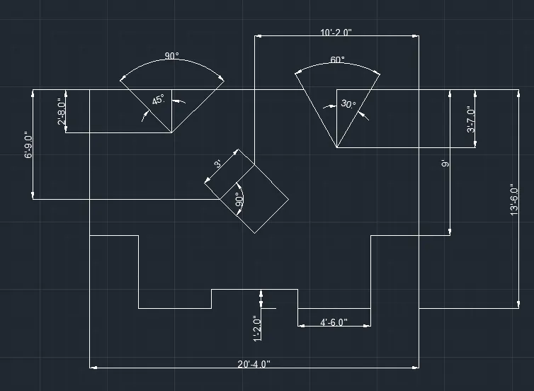
RESULT :The given geometrics are drafted using chamfer, filler, circle and line tool in AutoCAD in accurate measurements