Creating a Floor plan, Footing detail and Isometric view using AutoCad
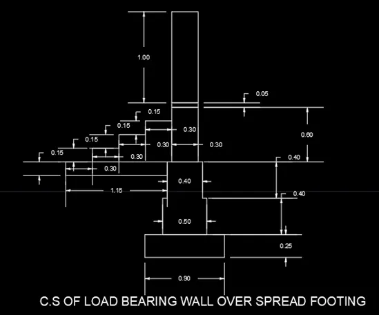
C1 Cross Section of load bearing wall over spread footing
AIM : To create cross section of load bearing wall over spread footing by using AutoCAD
INTRODUCTION: The cross section of load bearing wall over spread footing using AutoCAD is created by lines and Rectangules.The Procedure and result should be written after creating the cross section of load bearing wall over spread footing.
PROCEDURE:
Step 1 :
- Open the AutoCAD software and click start drawing tab
- Enter units in command box
- Select decimal and type 0.00 in precision and Meters in units to scale inserted contect
- Switch on ORTHOMODE
- Enter REC in the command box
- Enter first corner point as 0,0 in the command box
- Click dimenssions in the other coner point in the command box
- Enter 0.990 in length for rectangular in the command box
- Enter 0.25 width for rectangles in command box
Step 2
- Specify the first point 1,1 and press enter
- Specify the next point @0.90<0 and Press enter
- Specify the next point @0.25<90 and Press enter
- Specify the next point @0.10<180 and Press enter
- Specify the next point @0.50<180 and Press enter
- Specify the next point @0.10<180 and Press enter
- Specify the next point @0.25<270 and Press enter
- Specify the next point @0.40<90 and Press enter
- Specify the next point @0.05<0 and Press enter
- Specify the next point @0.40<90 and Press enter
- Specify the next point @0.05<0 and Press enter
- Specify the next point @0.40<90 and Press enter
- Specify the next point @0.25<90 and Press enter
- Specify the next point @1.15<180 and Press enter
- Specify the next point @0.15<180 and Press enter
- Specify the next point @0.30<0 and Press enter
- Specify the next point @0.15<90 and Press enter
- Specify the next point @0.30<0 and Press enter
- Specify the next point @0.15<90 and Press enter
- Specify the next point @0.15<90 and Press enter
- Specify the next point @0.30<0 and Press enter
- Specify the next point @0.15<90 and Press enter
- Specify the next point @0.30<0 and Press enter
- Specify the next point @1<90 and Press enter
- Specify the next point @0.30<0 and Press enter
- Specify the next point @1.75<270 and Press enter
- Specify the next point @0.05<270 and Press enter
- Specify the next point @0.30<180 and Press enter
- Specify the next point @0.05<270 and Press enter
- Specify the next point @0.30<180 and Press enter
- Specify the next point @0.05<270 and Press enter
Step 3
Again Enter Line command in COmmand Box and Press Enter
Specify the same line point and pres enter
- Specify the next point @0.65<0 and Press enter
- Specify the next point @0.60<270 and Press enter
- Specify the next point @0.65<180 and Press enter
- Specify the next point @0.40<270 and Press enter
- Specify the next point @0.15<180 and Press enter
- Specify the next point @0.40<270 and Press enter
- Specify the next point @0.20<180 and Press enter
- Specify the next point @0.25<270 and Press enter
RESULTS:
- C.S of load bearing wall in spread footing is created by LINES and RECTANGLES by using AutoCAD
- The Step-by-Step procedure is explaind for creating load bearing wall on spread footing
- Dimensions are heading are also entered in the diagram, All Dimensions are in mm
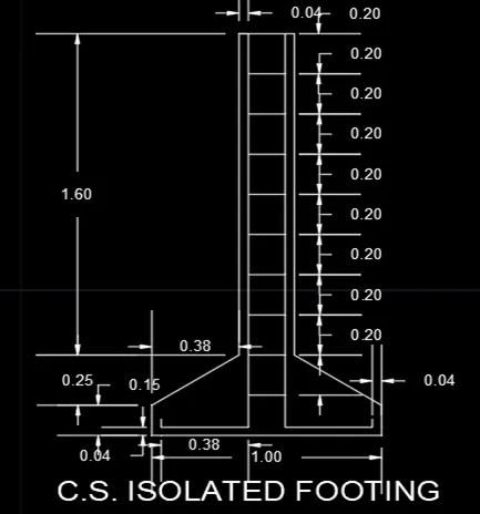
C2 Cross Section of isolated footing
AIM : To create cross section of isolated footing by using AutoCAD
INTRODUCTION:
- The CROSS-SECTION OF ISOLATED FOOTING USING AUTOCAD IS CREATED BY LINES
- THE PROCEDURE AND RESULT IS WRITTEN AFTER CREATING THE CROSS-SECTION OF ISOLATED FOOTING
PROCEDURE :
ISOLATED FOOTING
Type L command in command box, enter
- Specify the first point1,1 and press enter
- Specify the next point @1<0 and press enter
-
Specify the next point @0.15<90 and press enter
-
Specify the next point @0.38<150 and press enter
-
Specify the next point @1.60<90 and press enter
-
Specify the next point @0.24<180 and press enter
-
Specify the next point @1.60<270 and press enter
-
Specify the next point @0.38<200 and press enter
Specify the next point close or undo and press enter
Again type line command L, sfp 0.04,0.04 and press enter
-
Specify the next point @0.04<270 and press enter
-
Specify the next point @0.38<0 and press enter
-
Specify the next point @0.20<90 and press enter
-
Specify the next point @0.20<90and press enter
-
Specify the next point @0.20<90 and press enter
-
Specify the next point @0.20<90 and press enter
-
Specify the next point @0.20<90 and press enter
-
Specify the next point @0.20<90and press enter
-
Specify the next point @0.20<90and press enter
-
Specify the next point @0.20<90 and press enter
-
Specify the next point @0.20<90 and press enter
-
Specify the next point @0.20<90 and press enter
-
Specify the next point @0.16<0 and press enter
Specify the next point close or undo it and press enter
Then type offset command in command box, "0" enter
Offset the top of the lines 0.16 to through 0.20 and press enter
Repeat the same offset process to 9 times
Then Exits the command and enter
Then, give the " ALL DIMENSIONS" in mm
RESULTS
C.S of Isolated footing created by lines by using AutoCAD
Step-by-Step process for creating cross sections of isolated footings is explained
Dimensions are heading are also entered in the diagram, All Dimensions are in mm
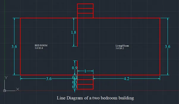
C3 The line diagram of a two bed room building
AIM : To create the line diagram of a two bed room building using AutoCAD
INTRODUCTION: The Line Diagram of a two bed room building using AutoCAD is created by lines.
The procedure and result should be written after creating the line diagram of a two bed room building.
PROCEDURE
Line Diagram of Two Bed Room Building
Then,Type L command on command box,and enter
- Specify the first point1,1 and press enter
- Specify the next point @3.60<0 and press enter
- Specify the next point @0.30<270 and press enter
- Specify the next point @0.30<270 and press enter
- Specify the next point @0.30<270 and press enter
- Specify the next point @1.00<0 and press enter
- Specify the next point @0.30<90 and press enter
- Specify the next point @0.30<90 and press enter
- Specify the next point @0.30<90 and press enter
- Specify the next point @4.20<0 and press enter
- Specify the next point @3.60<90 and press enter
- Specify the next point @4.20<180 and press enter
- Specify the next point @0.30<90 and press enter
- Specify the next point @0.30<90 and press enter
- Specify the next point @0.30<90and press enter
- Specify the next point @1.00<180 and press enter
- Specify the next point @0.30<90 and press enter
- Specify the next point @0.30<90 and press enter
- Specify the next point @0.30<90 and press enter
- Specify the next point @1.00<180 and press enter
- Specify the next point @0.30<270 and press enter
- Specify the next point @0.30<270 and press enter
- Specify the next point @0.30<270 and press enter
- Specify the next point @3.60<180 and press enter
Exit the Line command,
Then type the offset command in the command box
"0" enter to 1.00mm offset through 0.30mm 2 times
Then Exit the offset comand.
Give ALL DIMENSIONS in mm
RESULTS :
The Line Diagram of Two Bed Room Building is created by line by using AutoCAD
The Step-by-Step Procedure of Two Bed Room Building is explained
Dimensions are heading are also entered in the diagram, All Dimensions are in mm
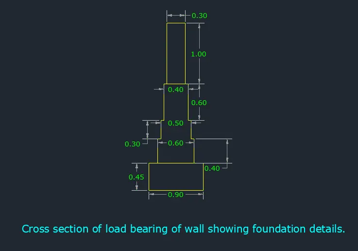
C4 Load Bearing Wall showing Foundation Details
AIM : To create Load Bearing Wall showing Foundation Details
INTRODUCTION: The C.S of Load Bearing Wall using Foundation Details using AutoCAD is created by lines and rectangles the procedure and results should be shown after creating load bearing wall showing foundation details
PROCEDURE
C.S of load bearing wall showing foundation details;
Type L command in the command box, and enter
- Specify the first point 1,1 and press enter
- Specify the next point @0.90<0 and press enter
-
Specify the next point @0.45<90 and press enter
-
Specify the next point @0.15<180 and press enter
-
Specify the next point @0.60<180 and press enter
-
Specify the next point @0.15<180 and press enter
Exit Line Command and again type i enter
Specify the first point pick the 0.40 point in X-Axis
-
Specify the next point @0.40<90 and press enter
-
Specify the next point @0.05<0 and press enter
-
Specify the next point @0.30<90 and press enter
-
Specify the next point @0.05<0 and press enter
-
Specify the next point @0.60<90 and press enter
-
Specify the next point @0.05<0 and press enter
-
Specify the next point @0.30<0 and press enter
-
Specify the next point @0.05<0 and press enter
-
Specify the next point @0.60<270 and press enter
-
Specify the next point @0.05<0 and press enter
-
Specify the next point @0.30<270 and press enter
-
Specify the next point @0.05<0 and press enter
-
Specify the next point @0.40<270 and press enter
Exit the Line Command,Again enter the line command
Specify the first point to pick the same point 0.30
-
Specify the next point @1.00<90 and press enter
-
Specify the next point @0.30<0 and press enter
-
Specify the next point @1<270 and press enter and exit the line command
RESULT
The C.S of Load Bearing of Wall Showing Foundation Details is created by line and rectangle by using AutoCAD
The Step-by-Step Procedure of Load Bearing of Wall Showing Foundation Details
Dimensions are heading are also entered in the diagram , All Dimensions are in mm
C5 ISOMETRIC VIEW OF STEPS
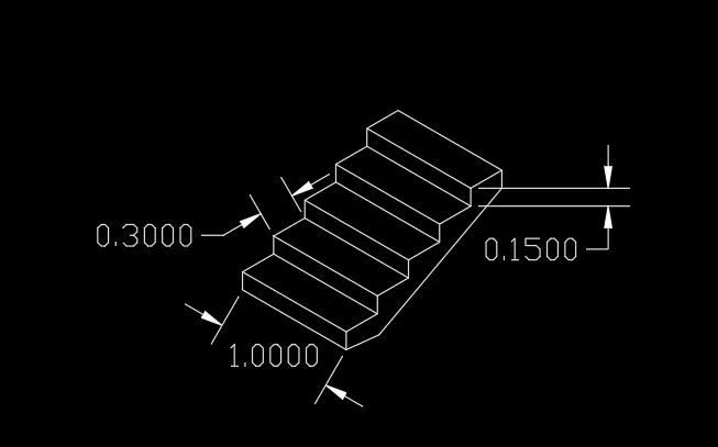
AIM : TO CREATE ISOMETRIC VIEW OF STEPS BY USING AUTOCAD
INTRODUCTION:
Isometric view of Steps by creating lines in AutoCAD,
The Procedure and Result should be written after creating the isometric view of steps
PROCEDURE
A 2D Isometric Drawing is a planar representation of a 3D isometric projections,Isometric view quickely communicates about the model for better understanding in addition to the other projection menthods
In AutoCAD, Isometric drawing are drawn using iso-planes,by using the Isodraft command,several system variable and settings automatically changed to vlaues that fecilitate isometric angles,
Following are the Iso-Plans in AutoCAD
- Right-Aligns snap and grid along 30 and 90 degree
- Left Aligns snap and Grid along 90 and 150 degree
- Top-Aligns snap and grid along 30 and 150 degree
Type L command on the command box and press enter
- Specify the first point 1,1 and press enter
- Specify the next point @0.15<90 and press enter
- Specify the next point @0.30<30 and press enter
- Specify the next point @0.15<90 and press enter
- Specify the next point @0.30<30 and press enter
- Specify the next point @0.15<90 and press enter
- Specify the next point @0.30<30 and press enter
- Specify the next point @0.15<90 and press enter
- Specify the next point @0.30<30 and press enter
- Specify the next point @0.15<90 and press enter
- Specify the next point @0.30<30 and press enter
- Specify the next point @1.00<110 and press enter
- Specify the next point @0.30<200 and press enter
- Specify the next point @0.15<270 and press enter
- Specify the next point @0.30<200 and press enter
- Specify the next point @0.15<270 and press enter
- Specify the next point @0.30<200 and press enter
- Specify the next point @0.15<270 and press enter
- Specify the next point @0.30<200 and press enter
- Specify the next point @0.15<270 and press enter
- Specify the next point @0.30<200 and press enter
- Specify the next point @0.15<270 and press enter
Exist Line Command and, Offset the above line (1.00mm) to through 0.30mm into 4 times
Then Again Offset the next line to 0.15 into 5 times and enter exist
RESULTS
The Isometric view of steps is created by line and rectangle by using AutoCAD
The Step-by-Step Procedure of Isometric view of steps is explained
Dimensions are heading are also entered in the diagram ALL DIMENSIONS are in mm
C6 ISOMETRIC VIEW OF CABLE WALL
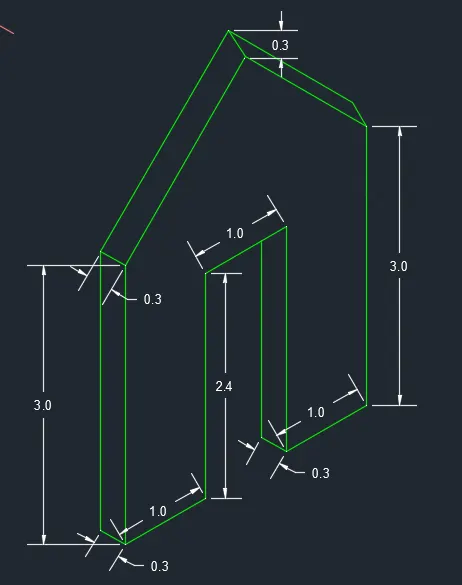
AIM : TO CREATE ISOMETRIC VIEW OF GABLE WALL BY USING AUTOCAD
INTRODUCTION:
Isometric view of Steps by creating lines in AutoCAD,
The Procedure and Result should be written after creating the isometric view of steps
PROCEDURE:
ISOMETRIC VIEW OF GABLE WALL
Type L command to the command box and enter
- Specify the first point1,1 and press enter
- Specify the next point @0.30<110 and press enter
- Specify the next point @1.00<30 and press enter
-
Specify the next point @2.42<90 and press enter
-
Specify the next point @1.00<30 and press enter
-
Specify the next point @2.42<270 and press enter
-
Specify the next point @3.00<90 and press enter
-
Specify the next point @0.30<110 and press enter
-
Specify the next point @1.50<120 and press enter
-
Specify the next point @1.50<225 and press enter
Exit the line command and press enter
RESULTS
The Isometric view of GABLE WALL is created by line and rectangle by using AutoCAD
The Step-by-Step Procedure of Isometric view of GABLE WALL is explained
Dimensions are heading are also entered in the diagram ALL DIMENSIONS are in mm