Sketch a G+1 residential plan according to Vaastu Shastra and Calculation of Loads as per IS code
AIM :
Sketch a G+1 floor residential plan, according to Vaastu Shastra, and list down the names of the structural drawings required to be provided to the site for construction.
Also, assume the sizes of the structural elements (Column, Beam, Slab, etc.,) and accordingly calculate the individual corresponding loads from the members as per IS code.
INTRODUCTION : Architects use drawings as a medium of communicating the design to the client or any related individual involved in constructing a project.
- For a project to be constructed, a final building contract, detailed specifications, and a certain set of working drawings is required, and this set of drawings is referred to as blueprints also.
- These documents are vital for building construction processes.
- The set of drawings in a working set is provided in a manner such that it corresponds to the building execution phases and procedure.
List of Drawings that are usually included in a working drawing set are as follows:
Working Drawing required:
- Title and Legend Sheet
- ARCHITECTURAL DRAWINGS
- Setting out Plan
- Centreline Plans
- Floor Plans (Detailed with grid Dimensions i.e. Centreline Markings)
- Sections and Details
- Elevations and Finish Details
- Opening Schedules
- STRUCTURAL DRAWINGS
- Trench Plan or Excavation Plan (according to Centreline Markings on Site)
- Foundation Plan
- Column Layouts
- Plinth Beam Layouts
- Roof Beam and Slab Layouts
- Consultant DRAWINGS
- Mechanical Drawing
- Electrical Drawings
- Plumbing Drawings
- Fire Safety Drawings
All of the above are essential for the completion of a project according to the designed concept idea with a scheduled project budget and estimations.
A brief description of each of the mentioned drawing is as follows:
1. Title and Legend Sheet
- It is required for the Introduction of the Project
- It includes a Design Proposal Title with a Schematic View or Elevation depicting the design by the architect
- It accommodates an index of all included drawings with the Designated Serial Number
2. Architectural Drawings
Set of Drawings prepared by Architects for conveying the Design idea of a Project.
2.1 Setting Out Plan
- These Plans include site layout proposal with built structure and its positioning according to references of markings or grid layout marked on the Site.
- It is used for marking the position and orientation of the structure according to the description provided by the architect.
- Reference point to initiate the construction are inferred from Setting out plan, Surface level markings are depicted on it (Mostly, Ground level being ±00 level for reference)
2.2 Centerline Plans
- Centrelines are grids that mark the positioning of any structural or non-structural element on-site about a coordinate on the grid.
(As shown in image, Vertical Axes are depicted through Alphabet Notations and Horizontal Axes are depicted through Number Notations, plotting both of these together forms a Grid.)
- Centrelines are depicted as Dash-Short Dashed line-type in drawings.
- It passes through the center or in the alignment of a column, or wall, or any demarked element to reference its position according to the grid as shown.
- Centreline Plans are used to generalise a common grid reference for all type of related construction works.
2.3 Floor Plans
- These blueprints depict the architect’s design as a scaled drawing showing a view from above through an imaginary horizontal sectional plane.
- Architectural floor plans are provided for construction of elements (walls, columns, trenches, etc) through markings and detailed dimensional distance from them concerning the Centreline grid as shown in image.
- These plans also include reference markings of any detail that requires any certain specification according to design. These specific details are separately shown for better readability and emphasis.
2.4 Sections and Details
- Sections are drawings depicting vertical sectional plane projections of the building showing its Interior and Exterior profiles and vertical dimensions of elements.
- Various forms of depiction of material, techniques, heights and openings are emphasized through lines and graphic conventions in Sections.
- Smaller yet Important Details are scheduled as Part-Section Details or Blow-up Details as shown in image (Wall Section Detail and Eave Detail).
2.5 Elevation and Finish Details
- Design Resultant of a building in architectural drawings is depicted through Elevations.
- Elevations are referential for the contractor or building to keep a check on how the building should shape after completion.
- These include Details like Finishes, Material Depiction through Graphical Notations, and Spot Elevation markings i.e. Level of Depth in a plane where the farthest plane is marked as ±00 level.
2.6 Opening Schedules
- Door-Window Schedules are a way of presenting complicated details of different doors and windows.
- It tabulates individual sizes, dimensions, and typologies of fenestration covering specified as per design.
- Details like Number, Material, Color and finish, Hinges and accessories, Fire Rating, Acoustic Rating and other remarks are supposed to be added in an Opening Schedule.
3. Structural Drawings
Set of Drawings created to construct the Structural Components of the building and representing the interconnectivity of beams, columns, stairs, slabs and thus alike.
3.1 Excavation Plan or Trench Plan
- On-site excavations or execution of Trenches for Sub-Structure of the building requires a plan where all the trenches are marked according to Grid of centreline markings and the offsets of dimensions respectively.
- Trench Plan highlights the dimensions (Length, Breadth, Depth) of trenches to be to excavated with reference to Centreline Grid.
- It is required at an early stage, immediately after marking Centreline on-Site.
3.2 Foundation Plan
- Structural drawing which has foundation notations with the dimensions (Length, Breadth, Thickness) of the column pad concerning the column placement according to the Centreline Grid markings.
- It also suggests the typology of the foundation to be used with any discreet specifications.
- Foundations are identified individually according to the coordinate on centreline grid as shown.
3.3 Coloumn Layout Plan
- Column Layouts are used for erecting columns on site as per project design
- These are referred onto the site for marking column placement, size and specifications of details of the column design.
- Any column on the layout has a certain Grid Coordinate on Centreline Grid that is used as its Column Nomenclature.
3.4 Plinth Beam Layout
- It is used for marking the Tie beam (Primary element for ‘Earthquake Resistant Structure’) which is used for connecting the columns emerging from the Sub-Structure (structure beneath the ground level) of the building.
- This layout gives the orientation of the Tie Beam to the column and also the Cross-section sizes with specifications of the design.
3.5 Roof, beam and Slab Layout
- It includes the layout of roof slabs concerning the corresponding beam by the Centreline Grid Markings of Columns-Beams.
- This involves the orientation of the roof slab and Reinforcement Bar Details to be incorporated according to Structural Design.
- Details like diameter and number of reinforcement bars in a defined length are mentioned in roof slab layout for structural stability.
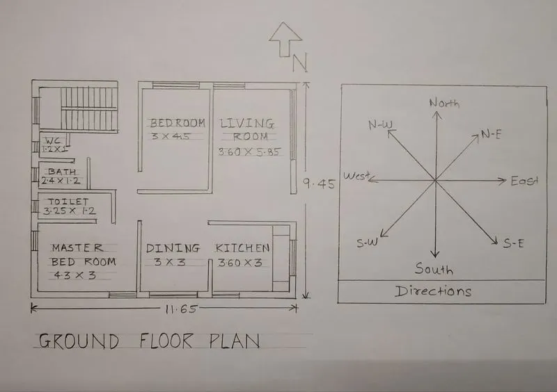
Dimensions of Ground floor
Living Room - 3.6*5.85
kitchen - 3.6*3
Dining - 3*3
Master Bed Room - 4.3*3
Childern Bed room - 3*4.5
Toilet - 3.25*1.2
Bath - 2.4*1.2
WC - 1.2*1
First Floor Plan
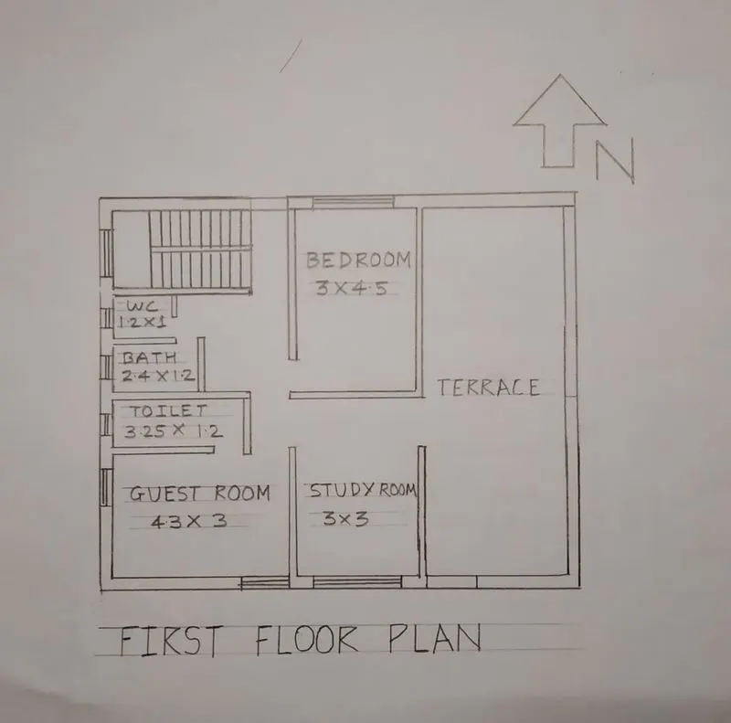
Dimensions of first floor
Guest Room = 4.3*3
Study Room = 3*3
Bed Room = 3*4.5
Toilet = 3.25*1.2
Bath = 2.4*1.2
WC = 1.2*1
Thickness of internal wall = 150mm
Thickness of external wall = 230mm
Thickness of slab = 250mm
Dimension of column = 0.3mm*0.3mm
Dimension of Beam = 0.3mm*4.5mm
Height of the wall for each floor = 3m
Calculations of Loads
Dead Load
Dead Load of column
D.L of colum = 0.3*0.3
Height of column = ( Slab Thickness *2) + ( Height of the wall for each floor *2)
= (0.25*2) + (3*2)
Total Volume of concrete = 0.3*0.3*6.5 = 0.585m^3
Unit weight of RCC = 25KN/m^3 ( As per IS 875 Part 1)
D.L of column = 25*0.585 = 16.42 KN/m^3
Dead Load of Beam
D.L of Beam = 0.3m*0.45m
Total Volume of concrete = 0.3*1*0.45 = 0.135m^3
Unit weight of RCC = 25KN/m^3 ( As per IS 875 Part 1)
D.L of column = 25*0.135 = 3.375 KN/m^3
Dead Load of Slab
D.L of slab is always designed for a span of 1m
Size of slab = 1m*1m
Thickness of slab = 0.25m
Density of RCC = 25KN/m^3
Self weight of slab = 1*1*0.25 = 6.25 KN
Live Load
According to IS 875 part 2
Bed Room = 2KN/m^2
Living Room = 2KN/m^2
Bath = 2KN/m^2
Terrace = 3KN/m^2
Kitchen = 2KN/m^2
StairCase = 3KN/m^2
Study Room = 2KN/m^2
Wind Load
- Wind Load is designed only when the height of the building exceeds 10m
- The Height of the designed building is 6.5 m only so Wind Load is not required
Vastu Tips for Home Planning and Design
1. Vastu Tips For Bedroom :
- Auspicious Placement of Master bedroom is very important for a Vastu House Map.
- South-West , West , West Of South west , North , and North-West good Position for Planning Bedroom.
- Never head towards north direction at the time of Sleeping .
2. Vastu Tips For Kitchen :
- South-East ( Agni Kon ) is Most preferable position for a Vastu Map .
- But Applied Vastu recommend South-of-South-East , West , and North-West also good placement of Kitchen as per Vaastu Shastra .
- Never Place kitchen in North , North East , East Direction.
3. Vastu for Living Room :
- Living Room is the place where most of the activity performed.
- Family recreation, social gathering , first impression created by a living Room.
- A living room must be clutter free , Impressive , Good Colour and light . Position of a living room depends on facing of House and space arrangement.
4. Vasthu For stair Case :
- As per Applied Vastu case study stair case is auspicious for all 16 Zones.
- People have some misconception on Placement of stair , Stair is heavy and many Vastu designer place it South , South-west and West Zone.
5. Vastu for Puja Room :
- Most preferable positon of Puja Room is Noth-East ( Ishaan ) Zone.
- A vastu Designer also can place Puja Room at West Zone of a Home.
6. Vaastu Tips For Dining Room :
- Dinning room is preferable in West , East , and South Direction.
- The distance of dinning and Kitchen should be minimum.
7. Vastu Tips For Toilets and Bath Rooms :
- Avoid construction of Toilet and Bathroom Ishaan ( North -East ) Zone.
- WNW , SSW , ESE are good Position for Placing Toilets.
- East of North East , East Good for Construction of Bath Room ( No Urinals ).