Creation of geometries by Coordinate system methods using AutoCad
AIM :
- Create the geometries from P1 to P2 using all the coordinates system methods.You need to use the Line tool to create the geometries. Where required you need to use the circle tool.
- Draw the profile and the trusses using any coordinate system methods
Introduction:
Before going to the drawing we should know about the co-ordinate system
- In AutoCAD there are two co-ordinate systems
Catresion and Polar
- By this co-ordinate system Absolute and relatve co-ordinate are applicable for autocad
There are three types of co-ordinate systems
- Absolute co-ordinate system
- Relative co-ordinate system
- Direct distance entry
Commands
- Line
- Dimlinear
- Text Command
- Circle Command
Procedure
Create the geometries from P1 to P2 using all the coordinates system methods and use the Line tool to create the geometries
a. Absolute Co-Ordinate System
P1 Drawing
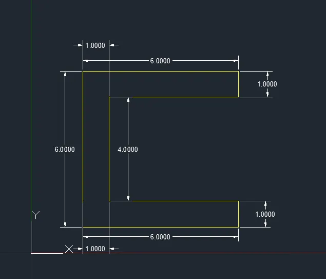
P1 Drawing using the absolute coordinate system
P2 Drawing
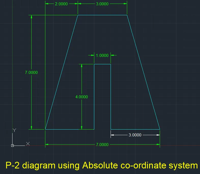
P2 Drawing using the absolute coordinate system
P3 Drawing
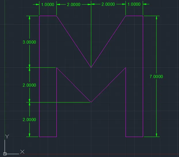
P3 Drawing using the absolute coordinate system
P4 Drawing
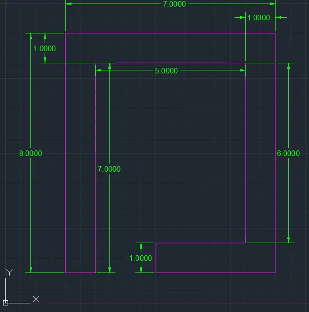
P4 Drawing using the absolute coordinate system
P5 Drawing
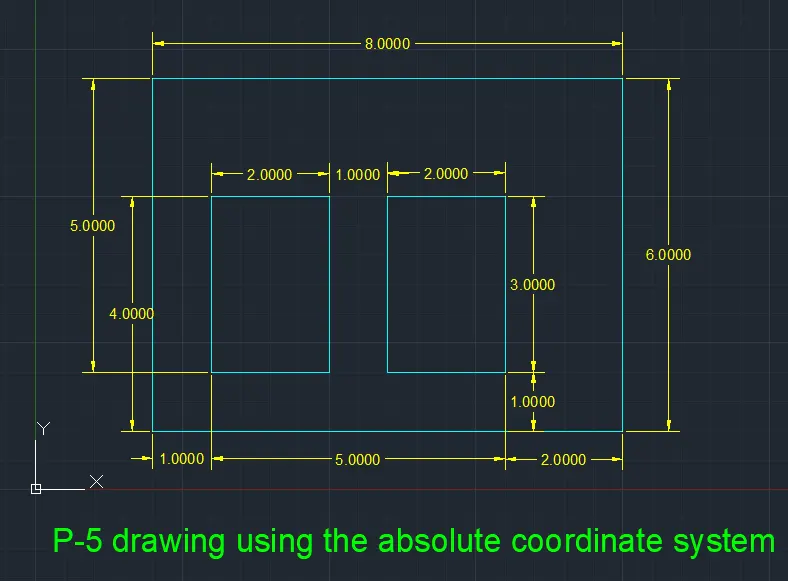
P5 Drawing using the absolute coordinate system
P6 Drawing
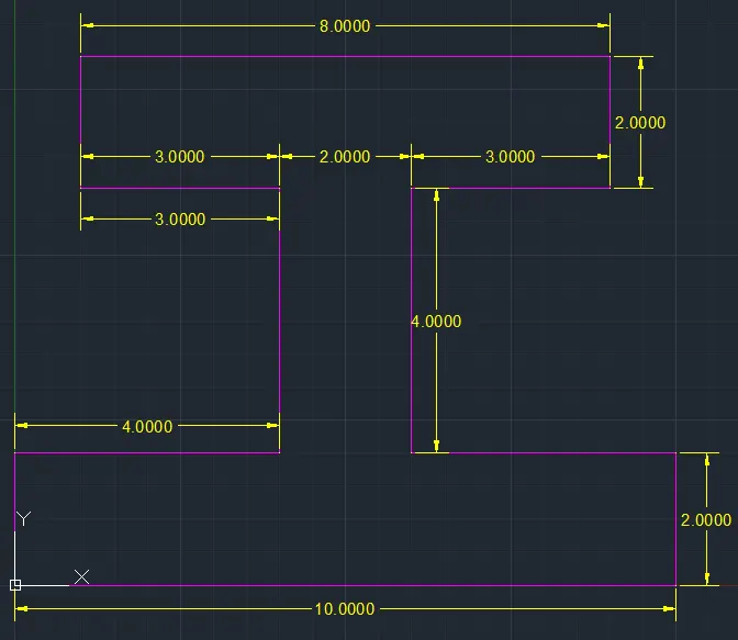
P6 Drawing using the absolute coordinate system
P7 Drawing
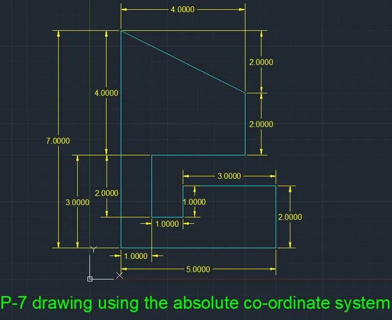
P7 Drawing using the absolute coordinate system
P8 Drawing
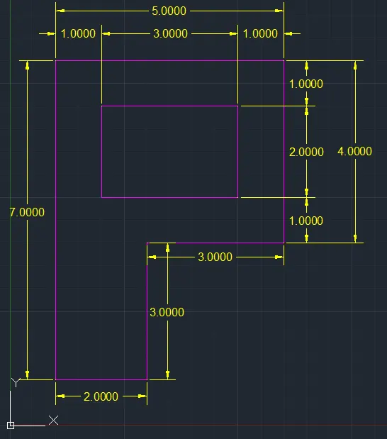
P8 Drawing using the absolute coordinate system
b.Relative Rectangular Co-ordinate system
P1Drawing
The co-ordinates of Relative Rectangular Co-ordinate system are
(2,1) (@6,0) (@0,1) (@-5,1) (@0,4) (@5,0) (@0,1) (@-6,1)
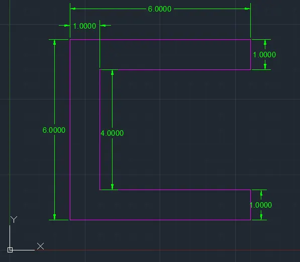
P1Drawing Relative Rectangular Co-ordinate system
P2 Drawing
The co-ordinates of Relative Rectangular Co-ordinate system are
(2,1) (@3,0) (@0,4) (@1,0) (@0,-4) (@3,0) (@-2,7) (@-3,0) (@-2,-7)
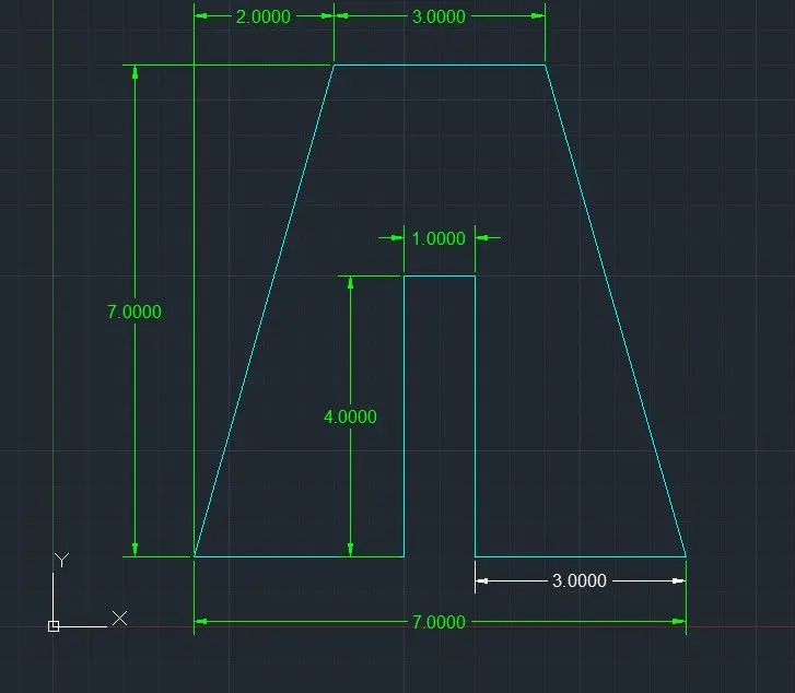
Relative Polar co-ordinate system
P1 Drawing
P1 Drawing Relative Polar co-ordinate system
P2 Drawing
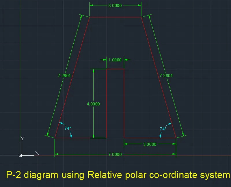
P2 Drawing Relative Polar co-ordinate system
c. Direct distance entry
P1 Drawing
P1 Drawing Direct distance entry
P2 Drawing
P2 Drawing Direct distance entry
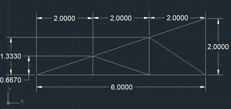
b. Draw the profile and the trusses using any coordinate system methods. The dimensions are there for references.
Profile Wood
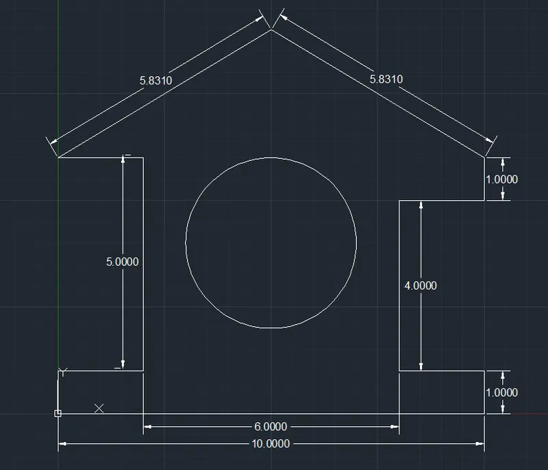
Mono Pitch
Results
- The geometrics is mentioned clearly in all the drawings and missing dimensions also mentioned
- Using all the coordinate system drawn all the drawings from P1-P2
- By using absolute coordinate system strusses are drawn