Drafting of various geometries using Chamfer, Fillet tool in AutoCad
AIM: To Draft of given geomentry using Chamfer, Fillet tool in AutoCad.
INTRODUCTION:
- Fillet tool and Chamfer tool which is used for the modification purpose in AutoCad.
- Fillet and Chamfer sketching can be done by using,Ribbon:Home>Modify>Fillet/Chamfer dop-down;Toolbar:Modify>Fillet/Chamfer;Command:Fillet/Chamfer .
- Fillet creats the curves between two straight lines by using radius or slecting the object option.
- In Chamfer tool, chamfer is created by using various options such as; select the first line/ distance option and angle option with one distance.
- Keeping on the OS settings in on mode which means using object snap by function key (F3) or else selecting from status bar.
- Then use the required object snap modes by clicking aganist them.
- It shows a tracking vector with the symbol of the slected mode when you move the cursor over the give point or segement of the command.
PROCEDURE:
- Select the line command from command prompt, specify the first point either by giving the coordinates or by manually to draft the given geomentry.
- Specify the next point or [undo]: 3.00
- Draft the given geomentry as per gevien dimensions using line comand.
- Set the UNITS in Decimals .
- Then by using the chamfer tool from command prompt draft the geomentry as specified.
- Then select the fisrt line or [undo]: angle/ with distance option.
- Specify chamfer length on first line <0.00>: 2.12.
- Specify chamfer angle from the first line <0.00>: 45.
- Specify chamfer length on first line <0.00>: 2.83.
- Specify chamfer angle from the first line <0.00>: 45.
- Specify chamfer length on first line <0.00>: 2.00.
- Specify chamfer angle from the first line <0.00>: 0.
- Then by slecting the Objectsnap settings from the staus bar/f3 functio key, ON Object snap modes.
- Then use the modes of the required ones.
- Then selecting middle point mode on, centre the middle of the line and by selcting offset mode>> offset the line by giving 1.00 .
- Draw a circle with centre as intersection point .
- specify the circle diameter as: 1.20.
- Then offset the line with displacement 2.50, make an intersection to draw a circle with diameter as:0.8.
RESULT:
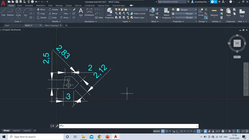
Therefore , the given geomentry has drafted by given dimensions.
2
AIM: To Draft of given geomentry using Chamfer, Fillet tool in AutoCad.
INTRODUCTION:
- Fillet tool and Chamfer tool which is used for the modification purpose in AutoCad.
- Fillet and Chamfer sketching can be done by using,Ribbon:Home>Modify>Fillet/Chamfer dop-down;Toolbar:Modify>Fillet/Chamfer;Command:Fillet/Chamfer .
- Fillet creats the curves between two straight lines by using radius or slecting the object option.
- In Chamfer tool, chamfer is created by using various options such as; select the first line/ distance option and angle option with one distance.
- Keeping on the OS settings in on mode which means using object snap by function key (F3) or else selecting from status bar.
- Then use the required object snap modes by clicking aganist them.
- It shows a tracking vector with the symbol of the slected mode when you move the cursor over the give point or segement of the command.
PROCEDURE:
- Select the line command from command prompt, specify the first point either by giving the coordinates or by manually to draft the given geomentry.
- Specify the next point or [undo]:
- Draft the given geomentry as per gevien dimensions using line comand.
- Set the UNITS in FEETS and INCHES .
- Then by using the chamfer tool from command prompt draft the geomentry as specified.
- Then select the fisrt line or [undo]: angle/ with distance option.
- Specify chamfer length on first line <0.00>: 8'.
- Specify chamfer length on first line <0.00>: 2'.5"
- Specify chamfer length on first line <0.00>: 3'
- Specify chamfer angle from the first line <0.00>: 45.
- Specify chamfer length on first line <0.00>: 2'.6".
- Specify chamfer length on first line <0.00>: 2'.10".
- Specify chamfer angle from the first line <0.00>: 135.
- Specify chamfer length on first line <0.00>: 1'.9".
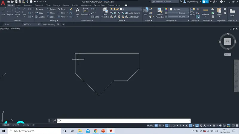
RESULT:
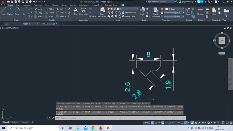
Therefore , the given geomentry has drafted by given dimensions.
3.
AIM: To Draft of given geomentry using Chamfer, Fillet tool in AutoCad.
INTRODUCTION:
- Fillet tool and Chamfer tool which is used for the modification purpose in AutoCad.
- Fillet and Chamfer sketching can be done by using,Ribbon:Home>Modify>Fillet/Chamfer dop-down;Toolbar:Modify>Fillet/Chamfer;Command:Fillet/Chamfer .
- Fillet creats the curves between two straight lines by using radius or slecting the object option.
- In Chamfer tool, chamfer is created by using various options such as; select the first line/ distance option and angle option with one distance.
- Keeping on the OS settings in on mode which means using object snap by function key (F3) or else selecting from status bar.
- Then use the required object snap modes by clicking aganist them.
- It shows a tracking vector with the symbol of the slected mode when you move the cursor over the give point or segement of the command.
PROCEDURE:
- Select the line command from command prompt, specify the first point either by giving the coordinates or by manually to draft the given geomentry.
- Specify the next point or [undo]:
- Draft the given geomentry as per gevien dimensions using line comand.
- Set the UNITS as engineering which means FEETS and INCHES.
- Then by using the chamfer tool from command prompt draft the geomentry as specified.
- Then select the fisrt line or [undo]: angle/ with distance option.
- Specify chamfer length on first line <0.00>: 5'.01".
- Specify chamfer length on first line <0.00>: 1'60"
- Specify chamfer angle from the first line <0.00>: 125.
- Specify chamfer length on first line <0.00>: 2'6.5".
- Specify chamfer length on first line <0.00>: 3'.30".
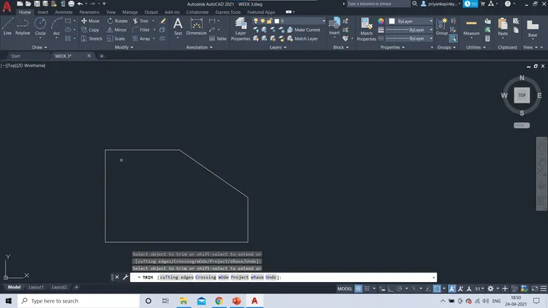
- Then by slecting the Objectsnap settings from the staus bar/f3 functio key, ON Object snap modes.
- Then use the modes of the required ones.
- Using Offset command , offset the line with diplacement of 1'60" vetsically, and horizonatally.
- Then ,draw the circle as centre as intersection point with diameter of 1'60".
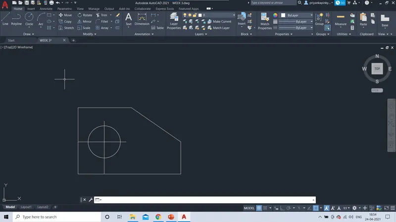
RESULT:
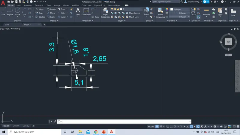
Therefore , the given geomentry has drafted by given dimensions.
4.
AIM: To Draft of given geomentry using Chamfer, Fillet tool in AutoCad.
INTRODUCTION:
- Fillet tool and Chamfer tool which is used for the modification purpose in AutoCad.
- Fillet and Chamfer sketching can be done by using,Ribbon:Home>Modify>Fillet/Chamfer dop-down;Toolbar:Modify>Fillet/Chamfer;Command:Fillet/Chamfer .
- Fillet creats the curves between two straight lines by using radius or slecting the object option.
- In Chamfer tool, chamfer is created by using various options such as; select the first line/ distance option and angle option with one distance.
- Keeping on the OS settings in on mode which means using object snap by function key (F3) or else selecting from status bar.
- Then use the required object snap modes by clicking aganist them.
- It shows a tracking vector with the symbol of the slected mode when you move the cursor over the give point or segement of the command.
PROCEDURE:
- Select the line command from command prompt, specify the first point either by giving the coordinates or by manually to draft the given geomentry.
- Specify the next point or [undo]:
- Draft the given geomentry as per gevien dimensions using line comand.
- Set the UNITS as Decimals .
- Then by using the chamfer tool from command prompt draft the geomentry as specified.
- Specify the polyline as fisrt point by giving coordinates or manually.
- Specify the next point or [length]: 3.00
- Specify the next point or [length]: 0.5 (cursor as downwads)
- Specify the next point or [length]: 2.00(right)
- Specify the next point or [length]: 2.50(up)
- Specify the next point or [length]: 2.00(left)
- Specify the next point or [length]: 3.00(up)
- Specify the next point or [length]: 2.50(left)
- Specify the next point or [length]: 2.00(down)
- Specify the next point or [length]: 1.00(left)
- Specify the next point or [length]/[close]: 3.50(down)
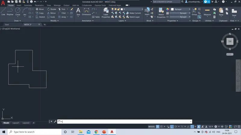
RSULT:
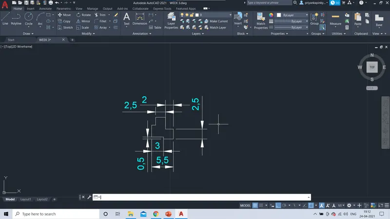
Therefore , the given geomentry has drafted by given dimensions.
5
AIM: To Draft of given geomentry using Chamfer, Fillet tool in AutoCad.
INTRODUCTION:
- Fillet tool and Chamfer tool which is used for the modification purpose in AutoCad.
- Fillet and Chamfer sketching can be done by using,Ribbon:Home>Modify>Fillet/Chamfer dop-down;Toolbar:Modify>Fillet/Chamfer;Command:Fillet/Chamfer .
- Fillet creats the curves between two straight lines by using radius or slecting the object option.
- In Chamfer tool, chamfer is created by using various options such as; select the first line/ distance option and angle option with one distance.
- Keeping on the OS settings in on mode which means using object snap by function key (F3) or else selecting from status bar.
- Then use the required object snap modes by clicking aganist them.
- It shows a tracking vector with the symbol of the slected mode when you move the cursor over the give point or segement of the command.
PROCEDURE:
- Select the line command from command prompt, specify the first point either by giving the coordinates or by manually to draft the given geomentry.
- Draft the given geomentry as per gevien dimensions using line comand.
- Set the UNITS in Decimals .
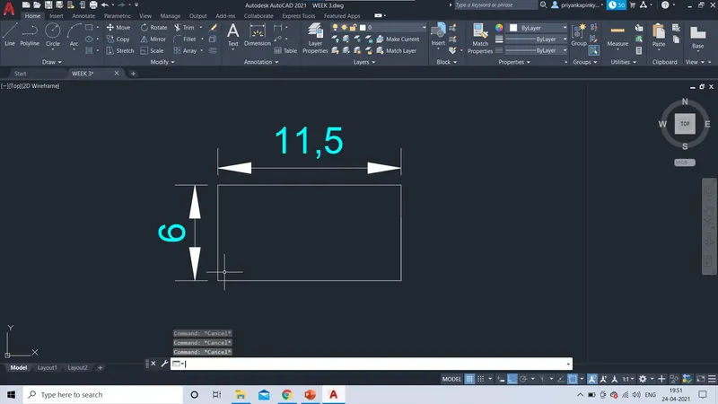
- Specify the next point or [undo]:11.50
- Specify the next point or [undo]:6.00
- Then by slecting the Objectsnap settings from the staus bar/f3 functio key, ON Object snap modes.
- Then use the modes of the required ones.
- By offset command >> make an offset of <3.00> from length (horizontally).
- Then by selection>> offset command as displacement 1.50 from width(6.00) make an offset on both sides ( vertical line)
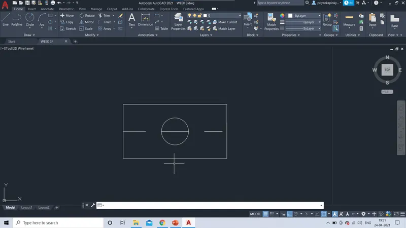
- Draw 2 cricles with centre as intersection of two offset lines with diameter< 1 >and< 2 >respectively.
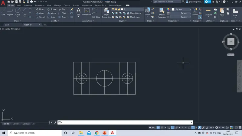
- Then again by taking the offset of newly form line of displacement 0f <4.25> with measures equal distance from both sides.
- Draw a circle with centre as intersection point with diameter of< 3> respectively.
RESULT:
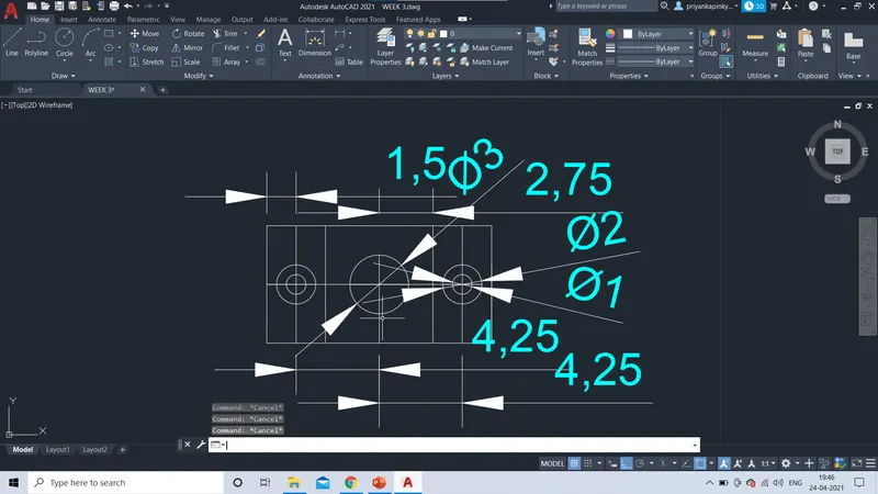
Therefore , the given geomentry has drafted by given dimensions.
6.
AIM: To Draft of given geomentry using Chamfer, Fillet tool in AutoCad.
INTRODUCTION:
- Fillet tool and Chamfer tool which is used for the modification purpose in AutoCad.
- Fillet and Chamfer sketching can be done by using,Ribbon:Home>Modify>Fillet/Chamfer dop-down;Toolbar:Modify>Fillet/Chamfer;Command:Fillet/Chamfer .
- Fillet creats the curves between two straight lines by using radius or slecting the object option.
- In Chamfer tool, chamfer is created by using various options such as; select the first line/ distance option and angle option with one distance.
- Keeping on the OS settings in on mode which means using object snap by function key (F3) or else selecting from status bar.
- Then use the required object snap modes by clicking aganist them.
- It shows a tracking vector with the symbol of the slected mode when you move the cursor over the give point or segement of the command.
PROCEDURE:
- Select the line command from command prompt, specify the first point either by giving the coordinates or by manually to draft the given geomentry.
- Draft the given geomentry as per gevien dimensions using line comand.
- Set the UNITS in Decimals .
- Specify the next point or [undo]:2.00
- Specify the next point or [undo]:1.50
- Specify the next point or[undo]: 0.5 , by giving vertical spacing which forms the given geomentry.
- Then draft the given geomentries of specified dimensions.
RESULT:
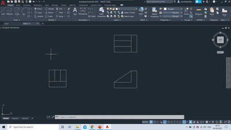
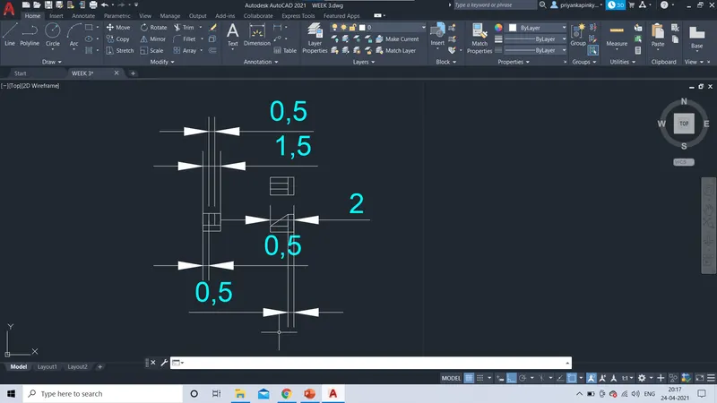
Therefore , the given geomentry has drafted by given dimensions.
7.
AIM: To Draft of given geomentry using Chamfer, Fillet tool in AutoCad.
INTRODUCTION:
- Fillet tool and Chamfer tool which is used for the modification purpose in AutoCad.
- Fillet and Chamfer sketching can be done by using,Ribbon:Home>Modify>Fillet/Chamfer dop-down;Toolbar:Modify>Fillet/Chamfer;Command:Fillet/Chamfer .
- Fillet creats the curves between two straight lines by using radius or slecting the object option.
- In Chamfer tool, chamfer is created by using various options such as; select the first line/ distance option and angle option with one distance.
- Keeping on the OS settings in on mode which means using object snap by function key (F3) or else selecting from status bar.
- Then use the required object snap modes by clicking aganist them.
- It shows a tracking vector with the symbol of the slected mode when you move the cursor over the give point or segement of the command.
PROCEDURE:
- Select the line command from command prompt, specify the first point either by giving the coordinates or by manually to draft the given geomentry.
- Specify the next point or [undo]: 210
- Specify the next point or [undo]:100
- Draft the given geomentry as per gevien dimensions using line comand.
- Set the UNITS in Decimals .
- Then by using the Fillet tool from command prompt draft the geomentry as specified.
- Then select the fisrt line or [undo]: radius/ select>> the object option.
- Select first object or radius<0.00>: R
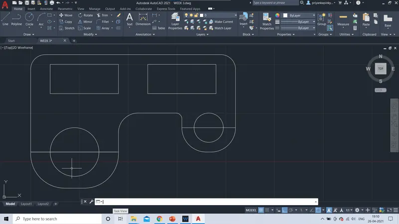
- Specify fillet radius <0.00>: 15; at both top corners of the given geomentry.
- Create two rectangles of specified deimensions as: < length:70>; <width:30> of an offset of displacement of 10 from top line.
- Draw cricles with center as midpoint at the bottom corners, create the two circles of diameter 50 on left bottom corner, and with diameter 30 on right bottom corner respectively.
- Using the fillet tool; on the bottom corners of the given geomentry makes cures of the corners.
- Specify the object radis <0.00>:R
- Specify fillet radius as <35> at left corner and fillet radius as < 25> at right corner respectively.
- Then,Specify fillet radius: <20.00> on left inner corner and fillet radius as < 6.00> on right inner corner.
RESULT:
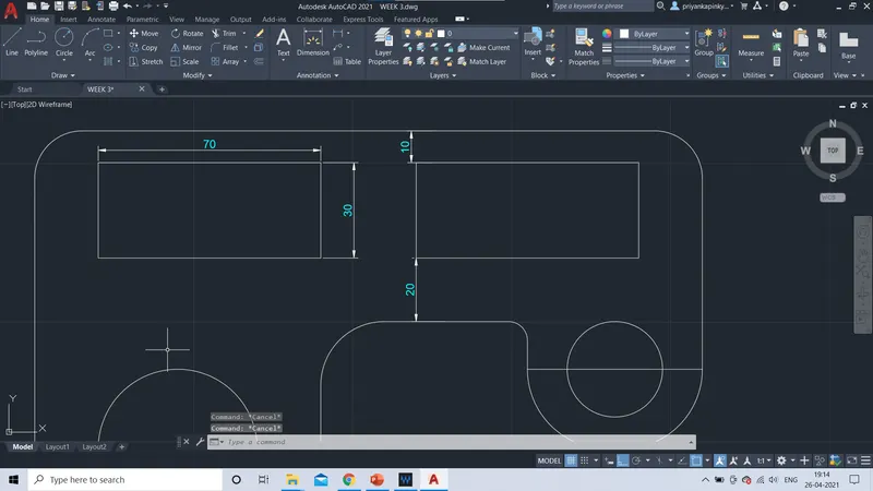
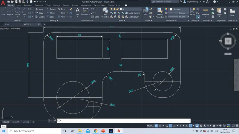
Therefore , the given geomentry has drafted by given dimensions.
8.
AIM: To Draft of given geomentry using Chamfer, Fillet tool in AutoCad.
INTRODUCTION:
- Fillet tool and Chamfer tool which is used for the modification purpose in AutoCad.
- Fillet and Chamfer sketching can be done by using,Ribbon:Home>Modify>Fillet/Chamfer dop-down;Toolbar:Modify>Fillet/Chamfer;Command:Fillet/Chamfer .
- Fillet creats the curves between two straight lines by using radius or slecting the object option.
- In Chamfer tool, chamfer is created by using various options such as; select the first line/ distance option and angle option with one distance.
- Keeping on the OS settings in on mode which means using object snap by function key (F3) or else selecting from status bar.
- Then use the required object snap modes by clicking aganist them.
- It shows a tracking vector with the symbol of the slected mode when you move the cursor over the give point or segement of the command.
PROCEDURE:
- Select the line command from command prompt, specify the first point either by giving the coordinates or by manually to draft the given geomentry.
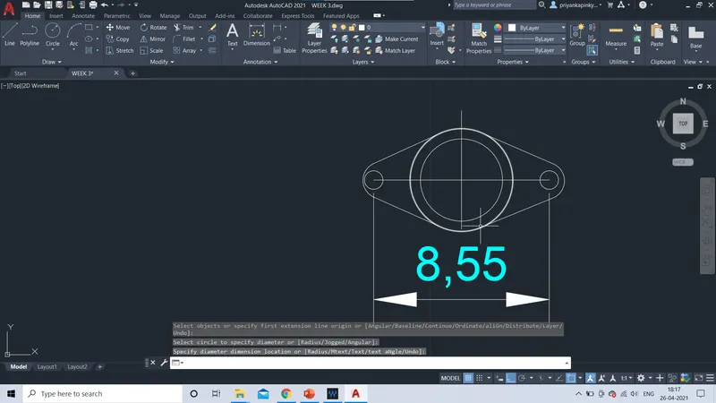
- Specify the next point or [undo]: 8.55
- Draw a line of distance 8.55.
- Then by slecting the Objectsnap settings from the staus bar/f3 functio key, ON Object snap modes.
- Then use the modes of the required ones; such as endpoint and mid point.
- Create the circles at two' endpoints 'and 'midpoint' of the line as centre of the circles with diameters as 0.9 at endpoint of the line.
- Then, create two circles with midpoint of the line as center with diameter of 4 and 5 respectively.
- Then by using the Fillet tool from command prompt draft the geomentry as specified.
- Then select the fisrt line or [undo]: radius/ select>> the object option.
- Select first object or radius<0.00>: R
- Specify fillet radius <0.00>: 0.90; at both endpoints the given line.
RESLT:
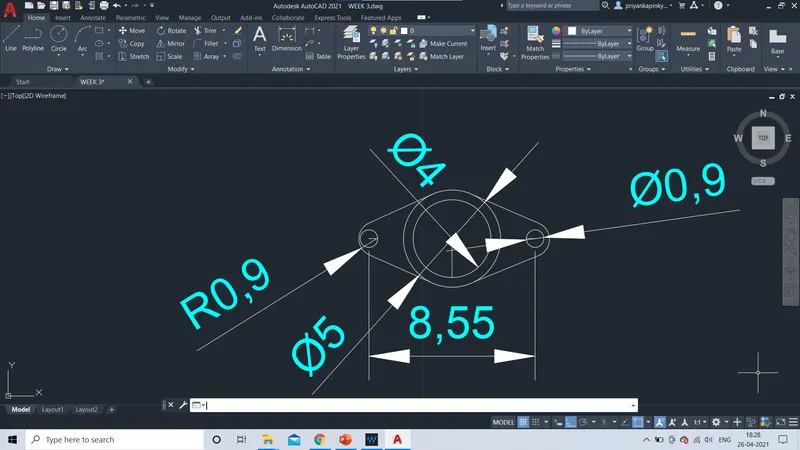
Therefore , the given geomentry has drafted by given dimensions.
9.
AIM: To Draft of given geomentry using Chamfer, Fillet tool in AutoCad.
INTRODUCTION:
- Fillet tool and Chamfer tool which is used for the modification purpose in AutoCad.
- Fillet and Chamfer sketching can be done by using,Ribbon:Home>Modify>Fillet/Chamfer dop-down;Toolbar:Modify>Fillet/Chamfer;Command:Fillet/Chamfer .
- Fillet creats the curves between two straight lines by using radius or slecting the object option.
- In Chamfer tool, chamfer is created by using various options such as; select the first line/ distance option and angle option with one distance.
- Keeping on the OS settings in on mode which means using object snap by function key (F3) or else selecting from status bar.
- Then use the required object snap modes by clicking aganist them.
- It shows a tracking vector with the symbol of the slected mode when you move the cursor over the give point or segement of the command.
PROCEDURE:
- Select the line command from command prompt, specify the first point either by giving the coordinates or by manually to draft the given geomentry.
- Specify the next point or [undo]: 32.6 ( ENGINEERING UNITS)
- Draw a line of distance 32.6.
- Then by slecting the Objectsnap settings from the staus bar/f3 functio key, ON Object snap modes.
- Create Two circles on both endpoints of the line.
- Specify the radius of circle: 8 ( left end point).
- Specify the radius of circle: 9 ( right end point).
- Using fillet command, from command prompt>> fillet.
- Specify the radius : R.
- Specify fillet radius as : <41.8 > on top end, <20.10> on bottom.
RESULT:
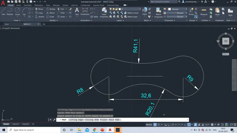
Therefore , the given geomentry has drafted by given dimensions.
10.
AIM: To Draft of given geomentry using Chamfer, Fillet tool in AutoCad.
INTRODUCTION:
- Fillet tool and Chamfer tool which is used for the modification purpose in AutoCad.
- Fillet and Chamfer sketching can be done by using,Ribbon:Home>Modify>Fillet/Chamfer dop-down;Toolbar:Modify>Fillet/Chamfer;Command:Fillet/Chamfer .
- Fillet creats the curves between two straight lines by using radius or slecting the object option.
- In Chamfer tool, chamfer is created by using various options such as; select the first line/ distance option and angle option with one distance.
- Keeping on the OS settings in on mode which means using object snap by function key (F3) or else selecting from status bar.
- Then use the required object snap modes by clicking aganist them.
- It shows a tracking vector with the symbol of the slected mode when you move the cursor over the give point or segement of the command.
PROCEDURE:
- Create a polygon of 4 sides using the command prompt>> polygon.
- Then create a polygon of radius 4 or manually with inscribed in circle
- Create an offset of diaplacement 0.05.
RESULT:
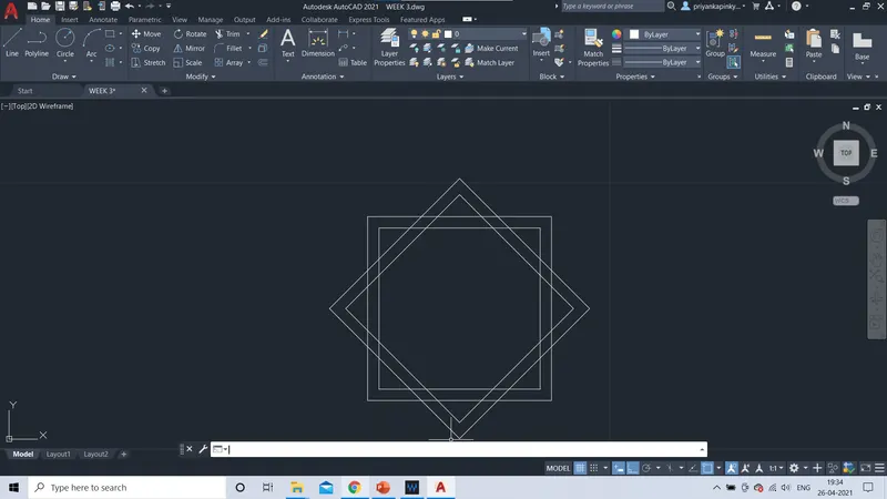
Therefore the given geomentry has drafted.
11.
AIM: To Draft of given geomentry using Chamfer, Fillet tool in AutoCad.
INTRODUCTION:
- Fillet tool and Chamfer tool which is used for the modification purpose in AutoCad.
- Fillet and Chamfer sketching can be done by using,Ribbon:Home>Modify>Fillet/Chamfer dop-down;Toolbar:Modify>Fillet/Chamfer;Command:Fillet/Chamfer .
- Fillet creats the curves between two straight lines by using radius or slecting the object option.
- In Chamfer tool, chamfer is created by using various options such as; select the first line/ distance option and angle option with one distance.
- Keeping on the OS settings in on mode which means using object snap by function key (F3) or else selecting from status bar.
- Then use the required object snap modes by clicking aganist them.
- It shows a tracking vector with the symbol of the slected mode when you move the cursor over the give point or segement of the command.
PROCEDURE:
- Select the line command from command prompt, specify the first point either by giving the coordinates or by manually to draft the given geomentry.
- Specify the next point or [undo]: 20.4
- Draft the given geomentry as per gevien dimensions using line comand.
- Set the UNITS in FEETS AND INCHES .
- Then by using the chamfer tool from command prompt draft the geomentry as specified.
- Specify the polyline as fisrt point by giving coordinates or manually.
- Specify the next point or [length]: 3'(right)
- Specify the next point or [length]: 4'.6".
- Specify the next point or [length]: 6'.7"
- Specify the next point or [length]: 3'(left)
- Specify the next point or [length]: 9"(up).
- Then select the fisrt line or [undo]: angle/ with distance option.
- Specify chamfer length on first line <0.00>: .3'.7"
- Specify chamfer angle from the first line <0.00>: 30
- Specify chamfer length on first line <0.00>: 3'.7".
- Specify chamfer angle from the first line <0.00>: 30.
- Specify chamfer length on first line <0.00>: 2'.8"
- Specify chamfer angle from the first line <0.00>: 45.
- Specify chamfer length on first line <0.00>: 2'.8"
- Specify chamfer angle from the first line <0.00>: 45.
- Using line command prompt specify the next point or [undo]: 6'.9" .
- Then excatly at centre of the geomentry,create a polygon.
- Specify the sides of polygon as:4
- Secify the radius of polygon as : 3'.00" .
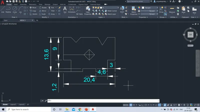
RESULT:
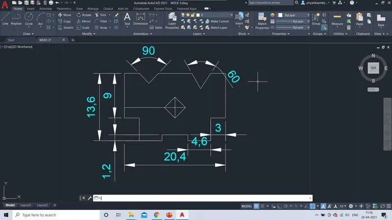
Therefore , the given geomentry has drafted by given dimensions.