Creating a Residence Layout, Seating plan, Toilet and Utility room plan using AutoCad
1,
AIM: To Sketch the layout of the residence as shown in figure 1.
INTRODUCTION:
- The commands used to sketch the given layout of residence are:
- Line command 'L' in the command prompt.
- Offset command 'Off' in the command prompt or else from ribbon tab.
- Trim command 'TRR' in the command prompt or else from ribbon tab.
- Circle command 'C' and all required commands used to sketch the given layout.
PROCEDURE:
- First set the units from the command prompt as mentioned in the given figure such as feets and inches.
- Then set the limits of the sheet, In the command prompt give the 'limits' and specify the limits.
- As the left corner is (x,y) as (0,0) and right corner as: ( 100',100').
- Then zoom the sheet .
- Then start the sketching of the layout of residence.
- Using 'XY line' from the command prompt.
- specify the vertical and horizontal lines and than trim off the unnecessary lines.
- Then using offset command, specify the offset distance ( as the outer wall lengths in horizontal and vertical directions) as: 25'and 43'6.5" respectively.
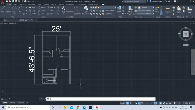
- Then offset the distance of 9'-0" which is the thickness of the outerwall and the inner wall thickness is 0'-4.5 ".
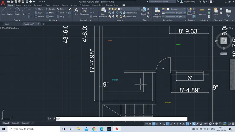
- Then offset distance of 6' from the previous outerwall and again offset the distance of 18'0.5" ( kicthen and dinning) in length direction.
- Then offset the distance of 11'3" as width of the bed 1 and the offset the inner wall thickness as 0'-4.5" and specify as offset distance as 11'10.5" for bed room 2 .
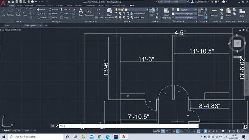
- Then using the trim command and, trim all the unnecessary lines and segments where required.
- Sketch the toilets with dimensions as 7'-10.5"*4'-6.02" and 8'-4.83"*4'-6.05" respectively.
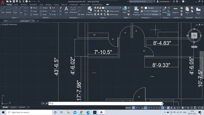
- Draft the the doors of three different dimensions as named as D1,D2,D3, as (D1, w-3';h-'6'-8");(D2, w-2'-6";h-'6'-8");(D3,w-3'-3";h-'6'-8") and skect at mentioned places from the figure.
- Specify the window of size 6'-0" in the outerwall of the entrance.
- Then specify the steps of 8 no's of rise 0'6" and thread 1'-0".
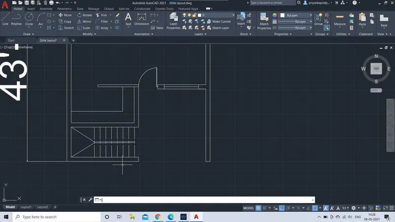
RESULT:
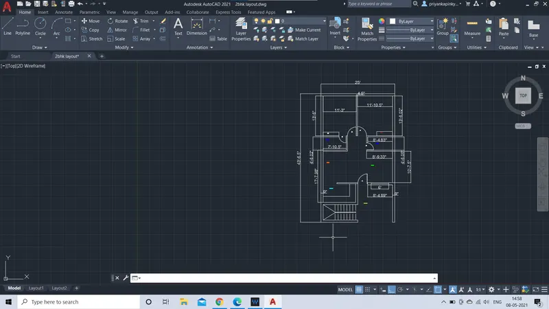
Therefore, the sketch of the given layout of residence is done with 2bhk specifications.
2
AIM: TO Sketch the seating plan for an outdoor canopy.
INTRODUCTION:
- The commands used to sketch the given Seating plan for an outdoor canopy:
- Line command 'L' in the command prompt.
- Offset command 'Off' in the command prompt or else from ribbon tab.
- Trim command 'TRR' in the command prompt or else from ribbon tab.
- Circle command 'C' and all required commands used to sketch the given canopy.
PROCEDURE:
- First set the units as units type decimals , which as dimensions in mm.
- Set the limits and zoom the layout of the drawing.
- Using Cricle command from ribbon tab, specify the centre point and of radius 452mm draw a circle respectively.
- As same point as centre, Draw a circle of radius 1398mm respectively.
- Then draft the seatings of assumed dimensions such as 400mm perfect square seatings.
- Using fillet command, specify the radius of 50mm on the first end corners.
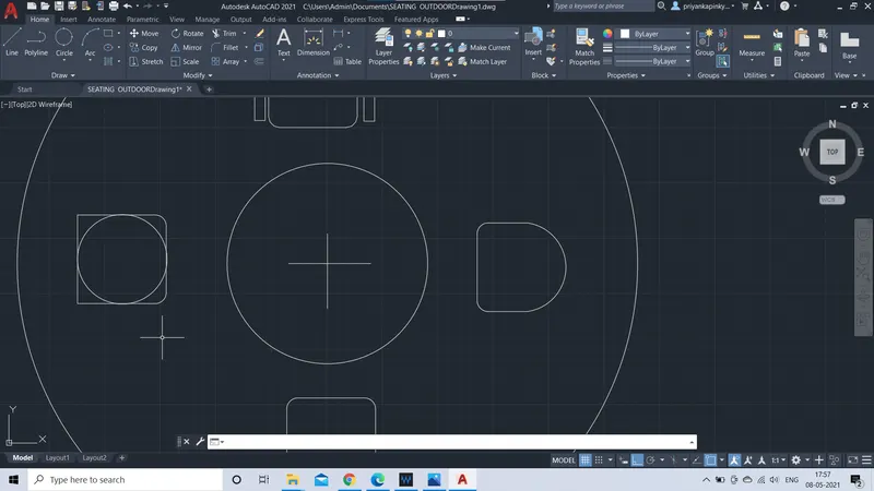
- Then, Using a circle command of type>> 3-point circle draw a circle which is enclosed in the square.
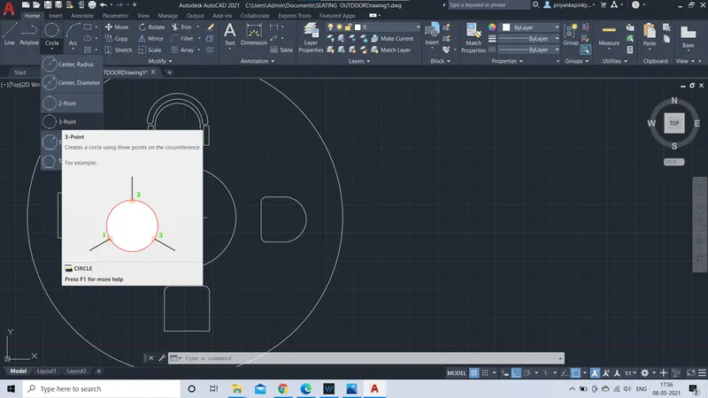
- Then, using commands like rectangle, and arc of 3-end-point type and offset coomand draft the seatings.
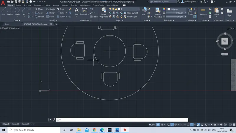
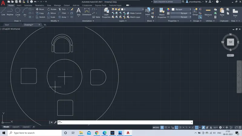
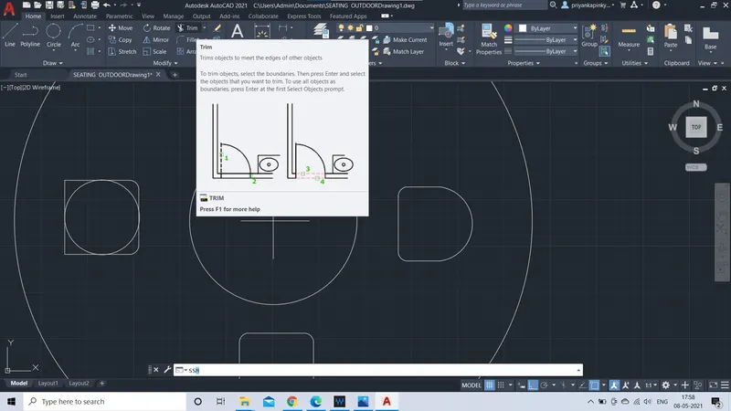
- At last trim all the unnecessary lines and segements to obtained the correct sketch of specified dimensions.
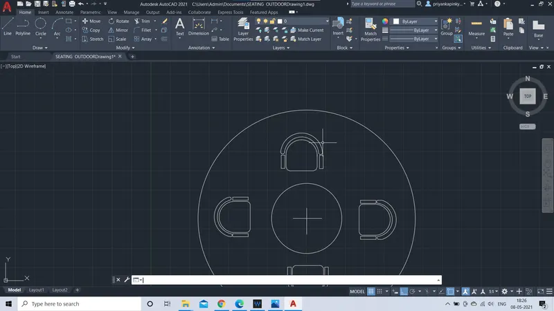
RESULT:

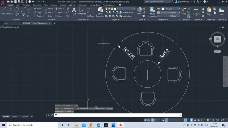
THEREFORE, The sketch of seating plan for an outdoor canopy has drafted with specified dimensions.
3
AIM: To Sketch the part plan for the toilers and utilities room.
INTRODUCTION:
- The commands used to sketch the given part plan ofresidence of toilers and utility room are:
- Line command 'L' in the command prompt.
- Offset command 'Off' in the command prompt or else from ribbon tab.
- Trim command 'TRR' in the command prompt or else from ribbon tab.
- Circle command 'C' and all required commands used to sketch the given layout.
PROCEDURE:
- First set the units as units type decimals.
- Set the limits and zoom the layout of the drawing.
- Sketch the toilers and utilities room of dimensions 1900*1700 and 1900*2100 respectively.
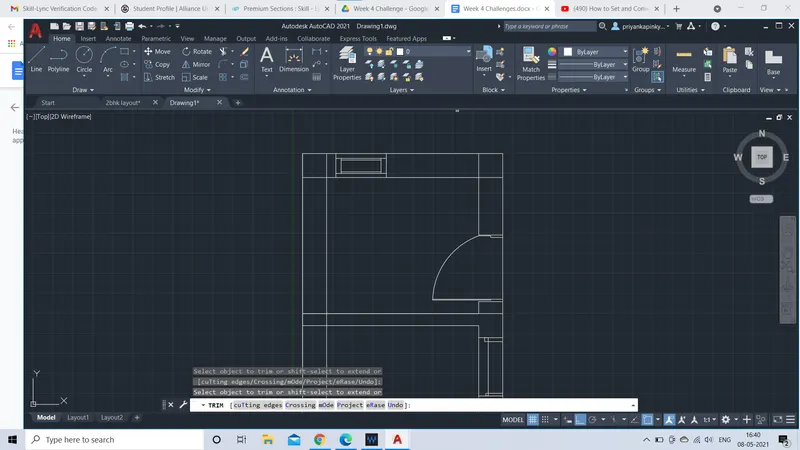
- Using the line command sketch the length and width of toilers and utilities room of specified dimensions.
- Using offset command, specify offset distance as 300mm for outerwall and 150mm for inner wall respectively.
- Then with given dimensions draft the windows and doors of toilers and utilities room.
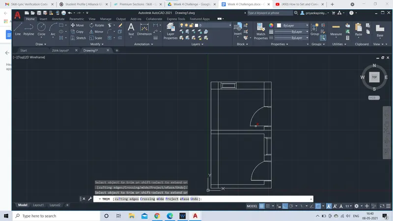
RESULT:
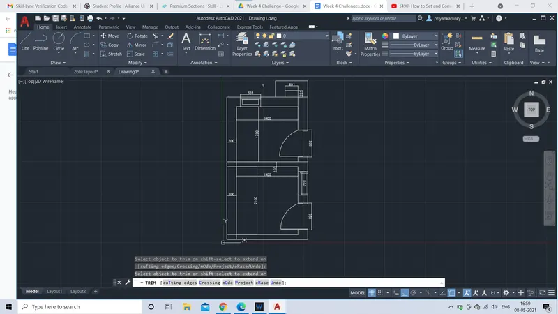
Therefore, the sketch of part of plan of an toilers and utilities room has been drafted neatly.