Creating a Wardrobe detailed drawing, Floor Plan, Kitchen Layout and Column Detail using AutoCad
1,
AIM: To draw the elevation and details of the wardrobe as shown in figure.
INTRODUCTION:
- The tools and commands used to draft the elevation and details of the wradrobe are:
- Line command, Offset command,Trim command were used to draft the wardrobe.
- In order to insert the text and specify the dimensions - MTEXT command and DIMLINEAR command.
- In this text and dimension were specified using LAYERS .
- Transparancy command was used where every required.
PROCEDURE:
- First set the drwaing units as Decimals type.
- Then fix the limits of the sheet as required.
- Using the line command draft the front elevation of the wardrobe and section 1 with reference to the figure given and the dimenisons mentioned.
- specify a point or [undo] as : 2800 and 2600.
- Which then forms a closed figure.
- Using Offset command , offset the lines with specified offset distance and draw the lines where ever required in order form the section 1 of the wardrobe.
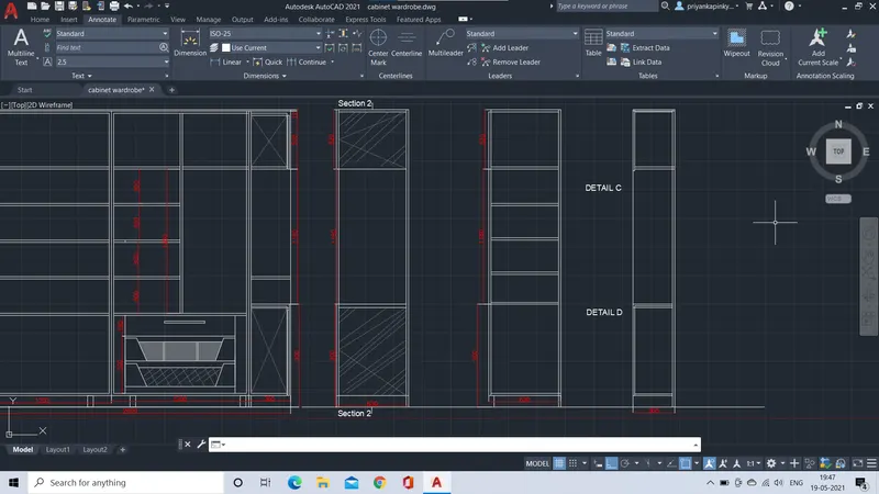
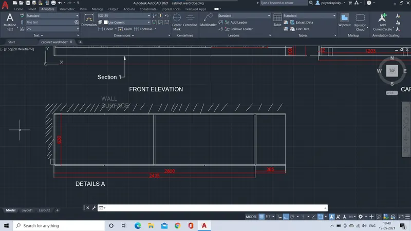
- Than as usualy to draft the Carcase elevation, Side elevation, section 2 and detials A, B, C and D of the warrobe use line command and offset command and also trim command.
- Then specify the text using MTEXT from command prompt and specify where every required.
- Then provide the dimension using DIMLINEAR command.
- At last specify the text and dimension in layers
- Create a new layer in Layer properties using Ribbon or command prompt.
- Give the name of the layer and select the text and dimensions to the specified layer.
RESULT:
FRONT ELEVATION
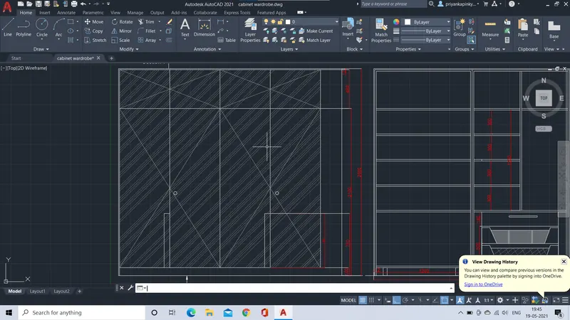
CARCASE ELEVATION -
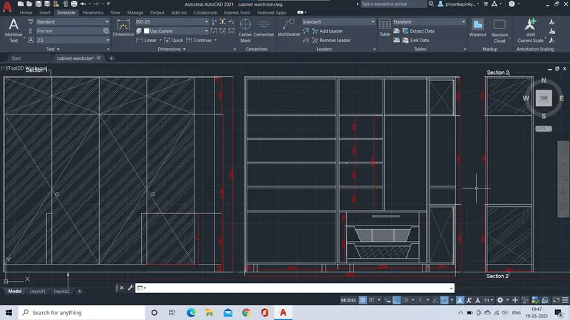
SIDE ELEVATION AND SECTION 2 WITH DEATILS B,C ,D
DETAILS OF A
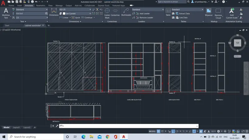
THE ELEVATION AND DETAILS OF THE WARDROBE AS SHOWN IN FIGURE HAS DEAFTED.
2,
AIM: To draw the Floor plan as shown in the figure.
INTRODUCTION:
- The tools and commands used to draw the floor plan are:
- Line command, Offset command,Trim command were used to draft the floor plan.
- In order to insert the text and provide to the dimensions - MTEXT command and DIMLINEAR command are used.
PROCEDURE:
- First set the drwaing units as Decimals type.
- Then fix the limits of the sheet as required.
- In the command prompt specify the XL command.
- It shows XL LINE specifies a point or [ ver hor ang bissect] as >> horizontal and vertical line.
- Then using offset command specify the offset of the room dimensions with reference to the given figure.
- In such a way draft the walls with 230mm and 150mm of offset distance for exterior and interior walls.
- In order to draw the living/ dinning room, toilets and utility rooms, bed room and guest bed room use offset command of specified offset distance with reference to the given figure.
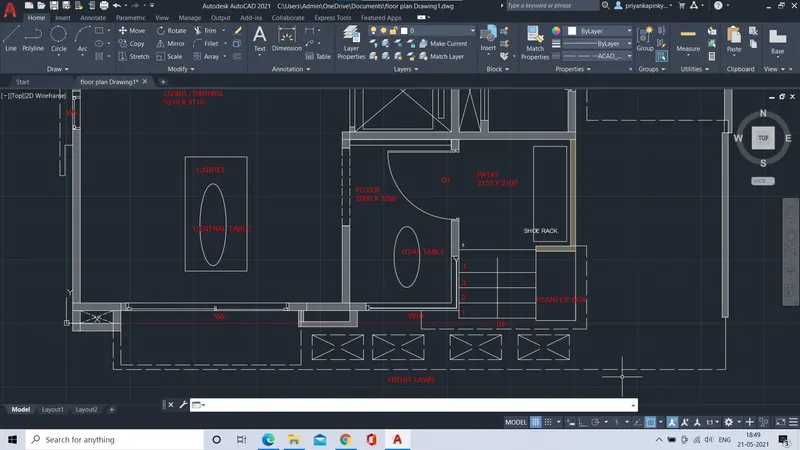
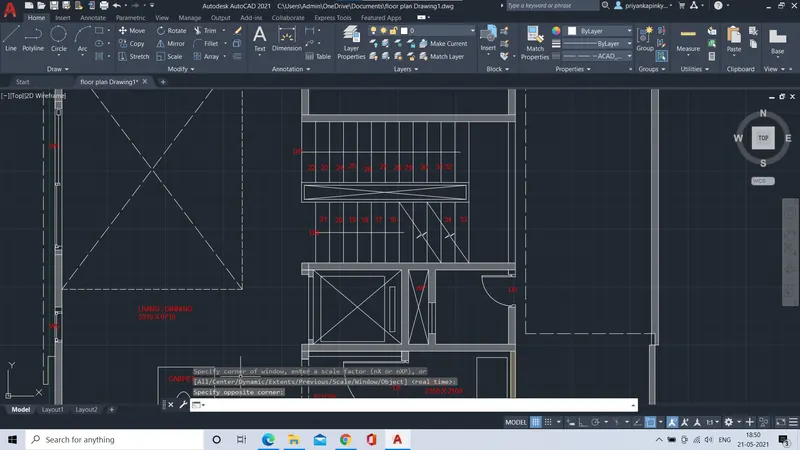
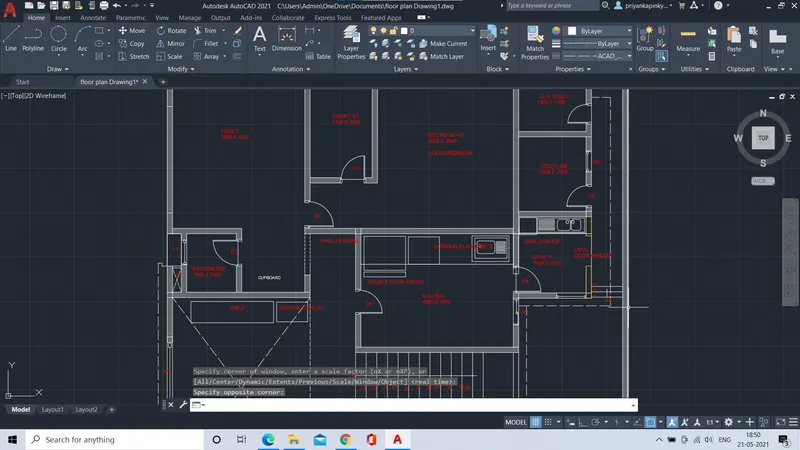
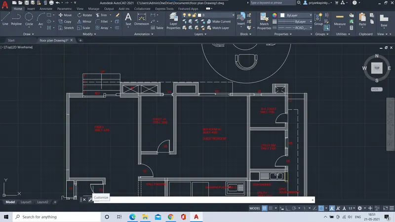
- Use the line command in order to draft the doors , windows and furniture with assumed dimensions and place where ever required.
- Draw strais of TREAD -300MM and RISER- 150MM using line command as mentioned .
- Use the trim commad where required in order to draft the neat sketch.
- Use the circle command and other drawing tools to draft the OUTDOOR SEATING CANOPY of assumed dimensions.
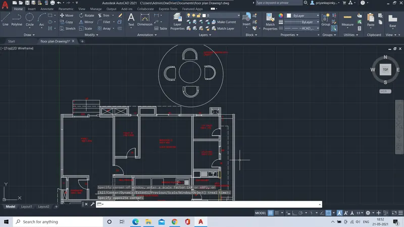
- Use mtext and dimlinear to provide the text and dimensions of the floor plan.
RESULT:
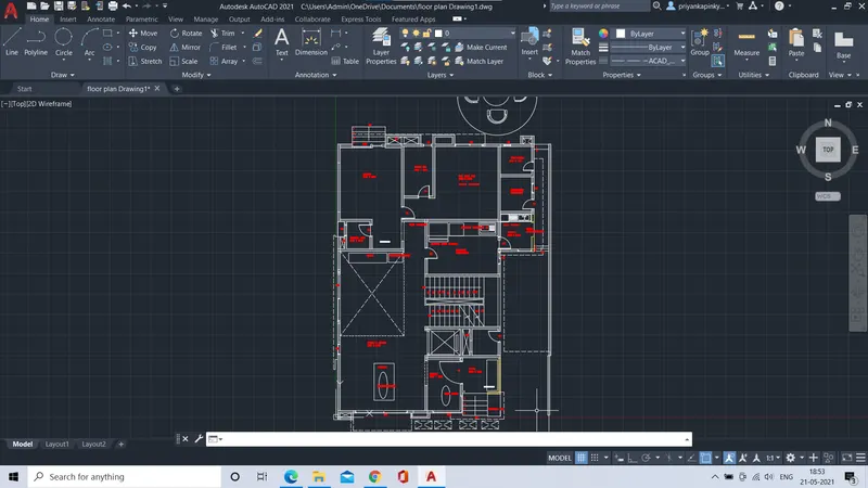
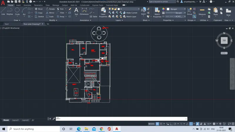
THE FLOOR PLAN HAS BEEN DRAFTED NEATLY.
3,
AIM: TO Create the Kitchen Layout as shown in figure.
INTRODUCTION:
- The tools and commands used to draft the Kitchen Layout are:
- Line command, Offset command,Trim command were used to create the kitchen layout.
- In order to insert the text and provide to the dimensions - MTEXT command and DIMLINEAR command are used.
- Use of hatch command to the hatch the walls of the kitchen layout.
PROCEDURE:
- First set the drwaing units as Decimals type.
- Then fix the limits of the sheet as required.
- In the command prompt specify the XL command.
- It shows XL LINE specifies a point or [ ver hor ang bissect] as >> draw horizontal and vertical line.
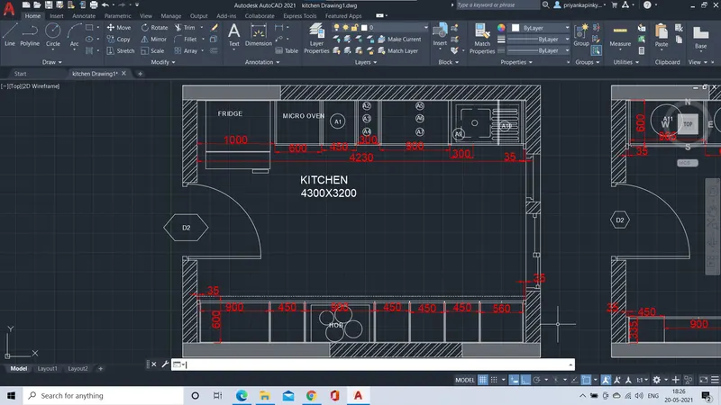
- Using offset command, specify the offset distance of 4300 in length direction and 3200 in width direction and draw for above and below counter plans.
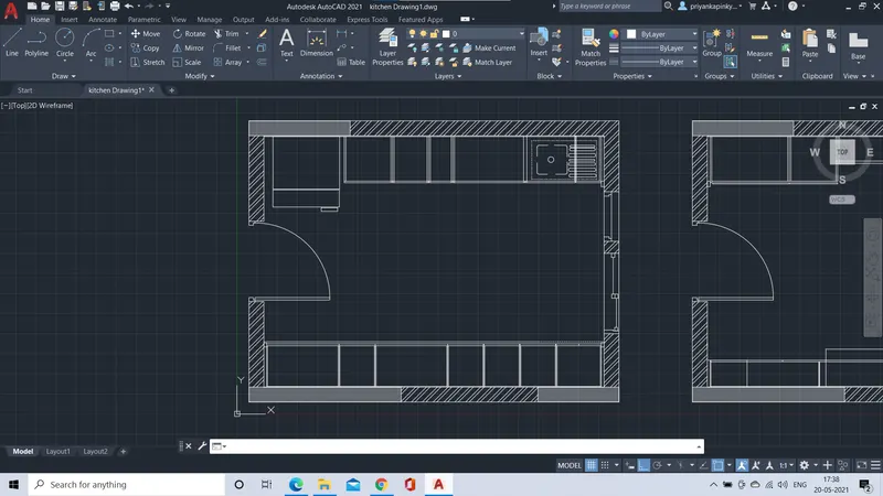
- As the walls of the kitchen walls come under interior walls , specify the offset of distance 150mm and create the walls of thickness 150mm.
- Then using Trim command trim all the unnecessary lines and segment.
- Then using line command and circle command create the door and window of assumed dimensions.
- Then using line command and offset command create the kitchen utilities of measurement with reference to the given figure.
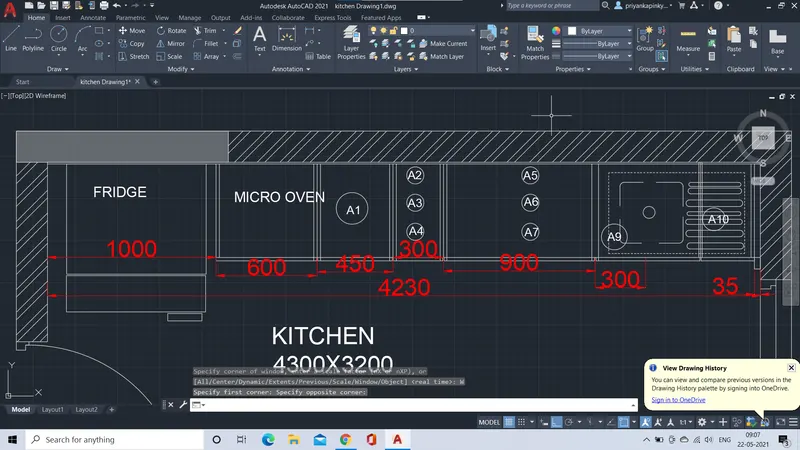
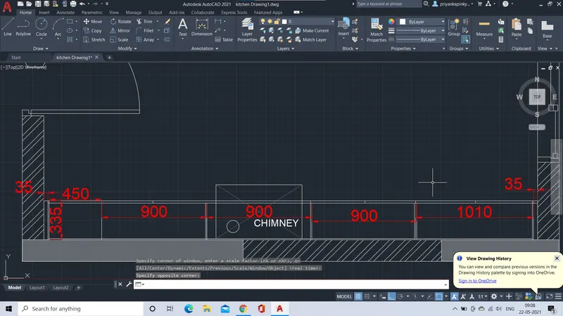
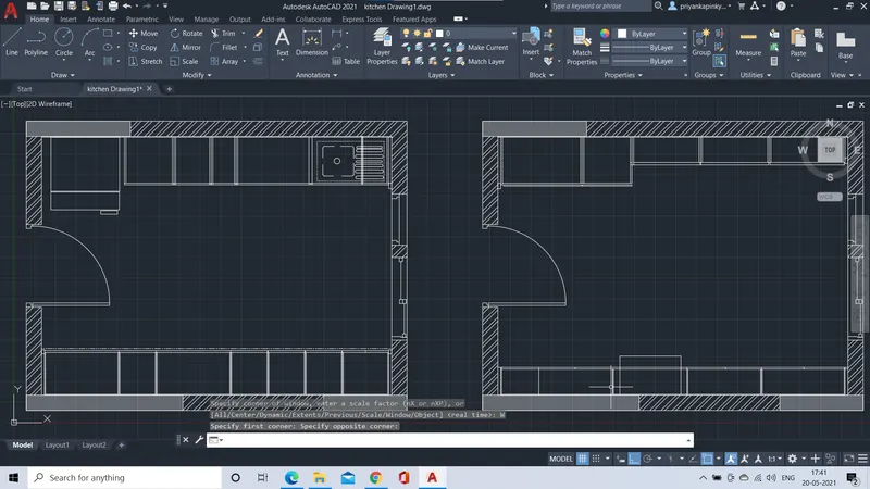
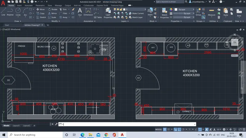
- Draft the kitchen layout showing the plan of below and above counter plan separately.
RESULT:
KITCHEN LAYOUT- BELOW THE COUNTER PLAN
KITCHEN LAYOUT- BELOW COUNTER PLAN WITH DIMENSIONS
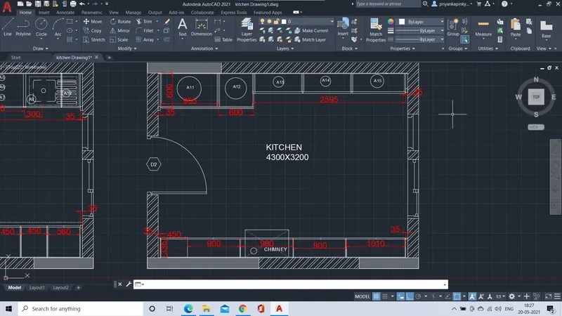
KITCHEN LAYOUT- ABOVE THE COUNTER PLAN
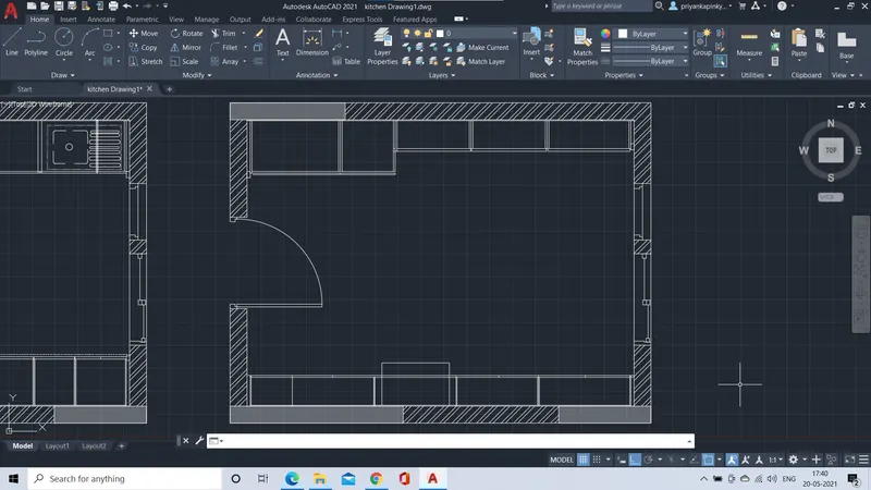
KITCHEN LAYOUT- ABOVE THE COUNTER PLAN WITH DIMENSIONS
THEREFORE, THE KITCHEN LAYOUT HAS BEEN DRAFTED BELOW
4,
AIM: To Sketch the column details of the given figure.
INTRODUCTION:
- The tools and commands used to Sketch the column details are:
- Line command, Offset command,Trim command were used to create the schedule of column details.
- In order to insert the text and provide to the dimensions - MTEXT command and DIMLINEAR command are used.
PROCEDURE:
- First set the drwaing units as Decimals type.
- Then fix the limits of the sheet as required.
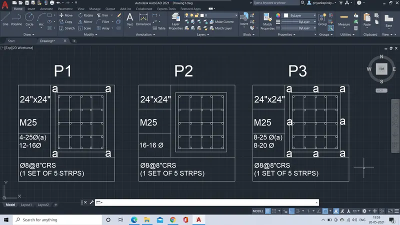
- Using the line command create the schedule
- Using the offset command, specify the offset distance of 400mm and 150mm to create the 2 no of columns and 4 no of rows.
- Using the copy tool, copy the drafted schedule of rows and column and name them as P1, P2, P3 using mtext command.
- Using the line command create the bar sizes of 8mm , 25mm, 16mm and insert into the schedule table.
- Using the MTEXT command insert the text into the sehedule.
RESULT:
THEREFORE, THE SKETCH OF THE COLUMN DETAILS HAS BEEN DONE
5,
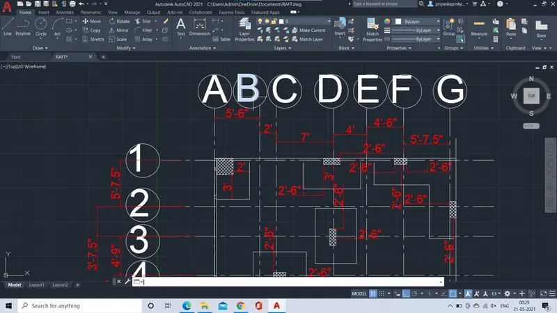
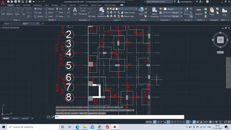
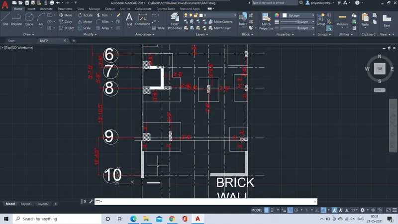
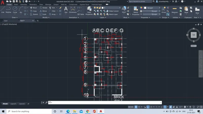
AIM: TO draw the Raft foundation as shown in the figure.
INTRODUCTION:
- The tools and commands used to Draw the Raft foundation plan are:
- Line command, Offset command,Trim command were used to crated raft foundation.
- In order to insert the text and provide to the dimensions - MTEXT command and DIMLINEAR command are used.
PROCEDURE:
- First set the drwaing units as Engineering type.
- Then fix the limits of the sheet as required.
- In the command prompt specify the XL command (change the line type >> center dash line).
- It shows XL LINE specifies a point or [ ver hor ang bissect] as >> horizontal and vertical line.
- Then using the offset command, specify the offset distance( refer the offset distance from given figure ) and draw horizontal and vertical lines to the grids.
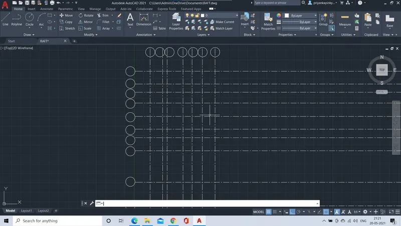
- Using Trim command ,trim the unnecessary line segmaents ans extra lines.
- Using the rectangle command, create the coulmn sizes of 24"x24",9"x24",9"x18".
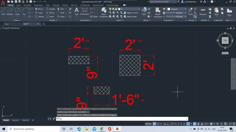
- Then insert the columns using copy command, and specify them as per the plan of the given raft foundation.
- Using DIMLINEAR and MTEXT command provide the text and dimensions respectively.
RESULT:
THEREFORE, THE RAFT FOUNDATION PLAN HAS DONE BELOW.