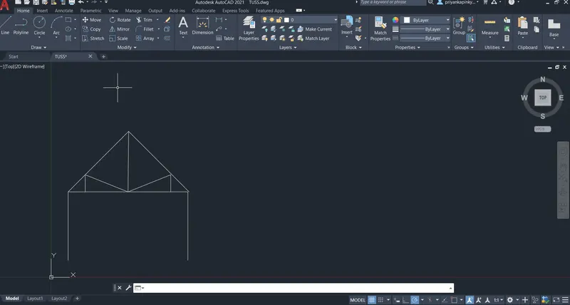
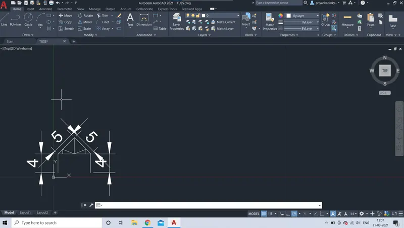
Creation of geometries by Coordinate system methods using AutoCad
AIM: To create the geometries of P-1 using absolute and relative coordinate systems.
INTODUCTION:
- Absolute coordinate system- In this method, we take all the points of an object with respect to origin.
- Relative coordinate system- In this method, we refer a point from the last point, as the first point of an object will be an absolute point. The change in the distance of the particular axes is take as delta and denoted by DX and DY respectively.
PROCEDURE:
- First select the line command from different alternates such as from tool bar, menu bar or from command box.
- In P-1 geometry, firstly by using absolute system
- Choose the line command as the start point of P-1 geometry coordinates are ( x,y) from origin are (2,1).
- Line specify the fisrt point as 2,1 and press enter key.
- Then specify the second point as (2,7), third point as (8,7), forth point as (8,6) likewise (6,3), (3,2), (8,2),(8,1) specifying all these points with respect to origin and at last close the line by absolute coordinate mehod.
- By using the relative coordinate system, specify the frist cordinates with respect to origin (0,0) and then specify the next points to form the given geometry with respect to the previous coordinates
- In the relative cordinate system the cordinates are related to the previous or last point of that particular coordinates.
- We use a specific character to specify the relative coordinates such as "@" .
- For the given P-1 geometry, specify first point as (2,1), second point as (DX=0,DY=6),
- In the command box specify coordinates such as :@,6 and click >> Enter key. As a same procedure by giving the particular relative change in coordinates create the P-1 geometry using relatie coordinate method.
RSULT:
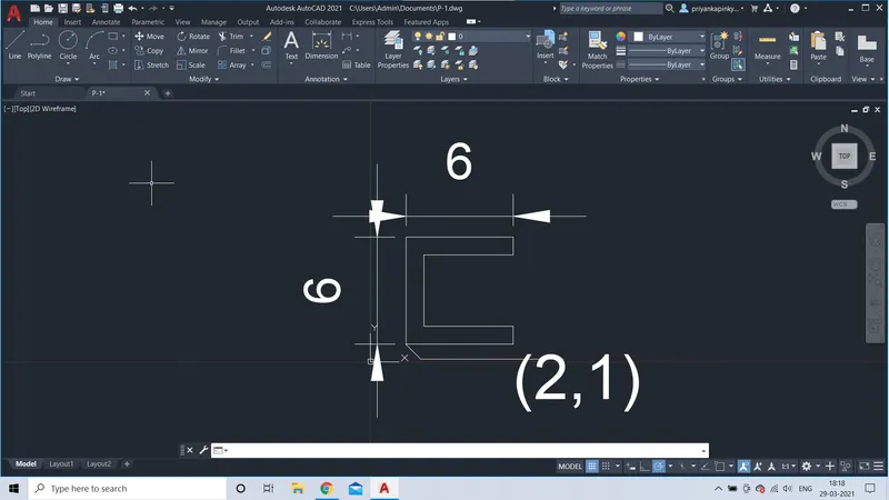
The above geometry is using by absolute coordinate method.
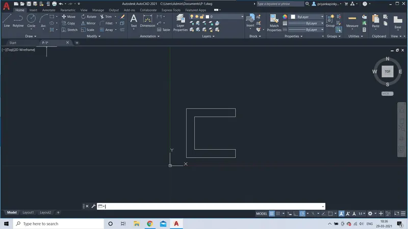
The above geometry is created by using relative coordinate method.
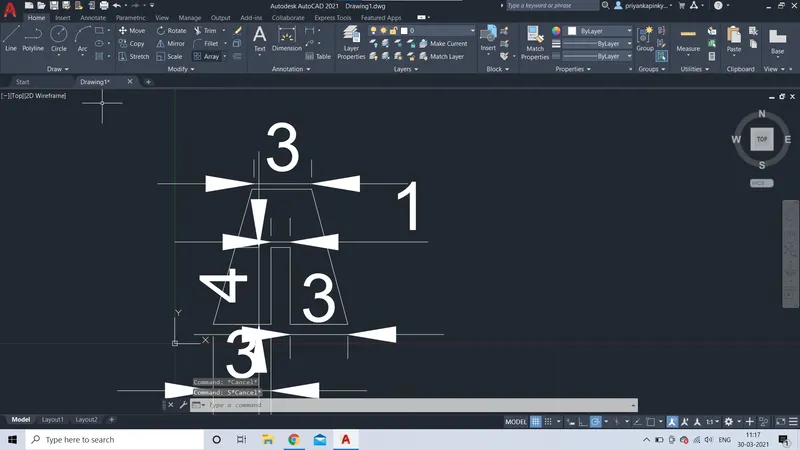
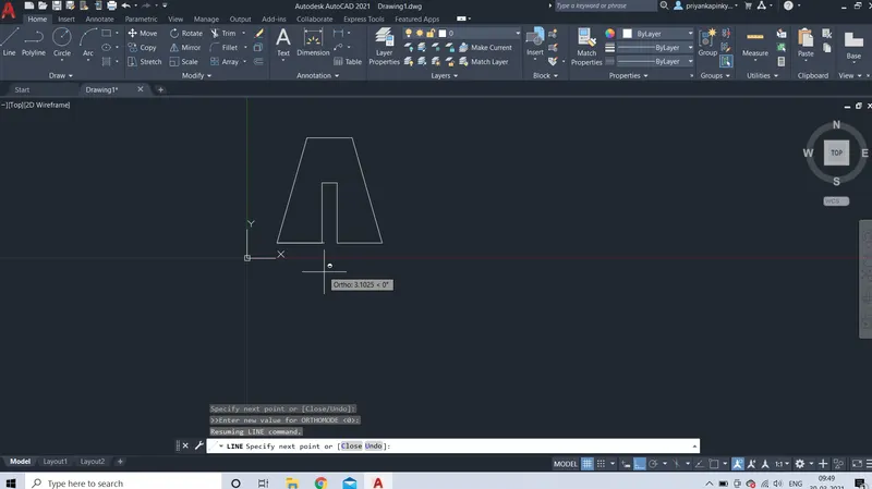
AIM: TO create the geometry of P-2 of given dimensions by using all coordiates methods.
- Absolute coordinate system- we create the geometry with respect to origin (0,0)in this method
- Relative coordinate system- In this coordinate system , to draw or create a geomentry we specify a point with respect to the pervious point , which is change in coordinate distance such as DX and DY and we use a character "@" to specify the coordinates.
- Relative polar coordinate- This type of coordinate system is used when there is an angle in the geometry, the combined line and angle can be formed using relative coorinate sysytem. To specify the angle we use the symbol "<" . For example we mention the format as ' @x distance< angle'.
PROCEDURE:
- To create the P-2 geometry, first select a new autocad file from application menu and set the units by 'UN' command on the command box.
- Choose the line tool.
- By following the absolute coordinates method specify the coordinates of a line to form given geometry.
- Line specify first point : (2,1) which is starting point.
- Specify the next points as :(5,1);(5,5);(6,5);(6,1);(9,1);(7,8);(4,8) and select >>[close] to complete the given geometry.
- Then by using the Relative coordinates system and Polar coordinates system specify points of a line to form geometry.
- Specify the first point of a line (2,1), then specify the next point with respect to the first point (2,1).
- The change in diatance with respect to the first point is DX and DY respectively such as @DX,DY.
- To specify the coordinates, the command is @3,0 with respect to (2,1) in such a way @0,1 ;@0,-4 ( - ve sign is taken when the coordinates move in -ve quadrants of that particular axes).
- In such a way when there is an angle , the specify the coordinates as "@distance<angle" which is polar coordinate system.
RESULT:
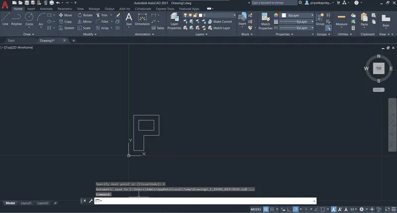
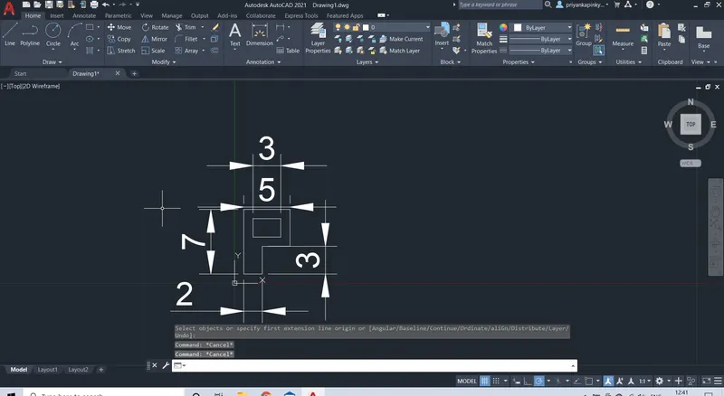
P-4
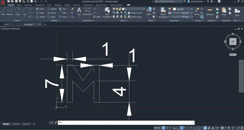
AIM: To create the P-4 geometry by using Relative coordinates method.
INTRODUCTION:
- Using relative coordinates method.
- start point of the P-4 geometry is (2,1).
PROCEDURE:
- Choose the Line command or tool.
- Line specify first point:(2,1) which is start point.
- Specify next point (or) undo:@Dx=0,DY=7(second point) and select the >> enter key.
- Specify next point (or) undo:@Dx=1,DY=1(third point) and select the >> enter key.
- Specify next point (or) undo:5,5 and next point as 7,8 .
- Specify next point (or) undo:@Dx=1,DY=0(sixth point) and select the >> enter key.
- Specify next point (or) undo:@Dx=-7,DY=0(seventh point) and select the >> enter key.
- Specify next point (or) undo:@Dx=1,DY=0(eighth point) and select the >> enter key.
- Specify next point (or) undo:5,3 and next point as 3,5 .
- Specify next point (or) undo:@Dx=0,DY=-4(sixth point) and select the >> enter key.
- Specify next point (or) [close/undo]
- There the given P-4 geometry is formed.
RESULT:
P-5
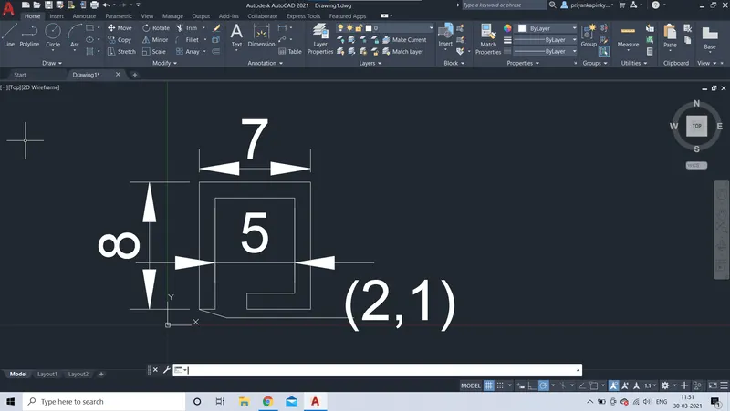
AIM: To create the P-5 geometry by using Relative coordinates method.
INTRODUCTION:
- Using relative coordinates method.
- start point of the P-5geometry is (2,1).
PROCEDURE:
- Choose the Line command or tool.
- Line specify first point:(2,1) which is start point.
- Specify next point (or) undo:@Dx=-4,DY=0(second point) and select the >> enter key.
- Specify next point (or) undo:@Dx=0DY=1 (third point) and select the >> enter key.
- Specify next point (or) undo:@Dx=3,DY=0(fourth point) and select the >> enter key.
- Specify next point (or) undo:@Dx=0,DY=6(fifthpoint) and select the >> enter key.
- Specify next point (or) undo:@Dx=-5,DY=0 (sixth point) and select the >> enter key.
- Specify next point (or) undo:@Dx=0,DY=-7(seventhpoint) and select the >> enter key.
- Specify next point (or) [close/undo]
- There the given P-5 geometry is formed.
RESULT:
P-7
AIM: To create the P-7 geometry by using Relative coordinates method.
INTRODUCTION:
- Using relative coordinates method.
- start point of the P-7geometry is (2,1).
PROCEDURE:
- Choose the Line command or tool.
- Line specify first point:(2,1) which is start point.
- Specify next point (or) undo:@Dx=0,DY=6(second point) and select the >> enter key.
- Specify next point (or) undo:@Dx=8,DY=0 (third point) and select the >> enter key.
- Specify next point (or) undo:@Dx=0,DY=-6(fourth point) and select the >> enter key.
- Specify next point (or) undo:@Dx=-8,DY=0(fifthpoint) and select the >> enter key.
- Specify next point (or) undo:@Dx=-5,DY=0 (sixth point) and select the >> enter key.
- Specify next point (or) undo: 3,2
- Specify next point (or) undo:@Dx=0,DY=3(seventhpoint) and select the >> enter key.
- Specify next point (or) undo:@Dx=2,DY=0(seventhpoint) and select the >> enter key.
- Specify next point (or) undo:@Dx=0,DY=-3(seventhpoint) and select the >> enter key.
- Specify next point (or) [close/undo]
- There the given P-7 geometry is formed.
RESULT: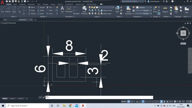
P-8
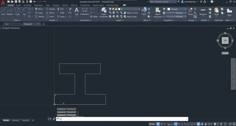
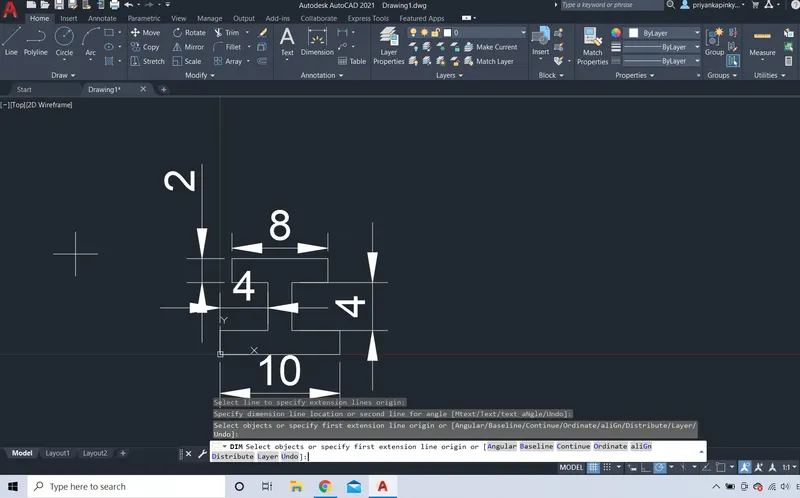
AIM: To create the P-8 geometry by using Relative coordinates method.
INTRODUCTION:
- Using relative coordinates method.
- start point of the P-8 geometry is (0,0).
PROCEDURE:
- Choose the Line command or tool.
- Line specify first point:(0,0) which is start point.
- Specify next point (or) undo:@Dx=0,DY=2(second point) and select the >> enter key.
- Specify next point (or) undo:@Dx=4,DY=0 (third point) and select the >> enter key.
- Specify next point (or) undo:@Dx=0,DY=4(fourth point) and select the >> enter key.
- Specify next point (or) undo:@Dx=-3,DY=0(fifthpoint) and select the >> enter key.
- Specify next point (or) undo:@Dx=0,DY=2 (sixth point) and select the >> enter key.
- Specify next point (or) undo:@Dx=8,DY=0(seventhpoint) and select the >> enter key.
- Specify next point (or) undo:@Dx=0,DY=-2(seventhpoint) and select the >> enter key.
- Specify next point (or) undo:@Dx=-3,DY=0(seventhpoint) and select the >> enter key.
- Specify next point (or) undo:@Dx=0,DY=-4(seventhpoint) and select the >> enter key.
- Specify next point (or) undo:@Dx=4,DY=0(seventhpoint) and select the >> enter key.
- Specify next point (or) undo:@Dx=0,DY=-2(seventhpoint) and select the >> enter key.
- Specify next point (or) [close/undo]
- There the given P-8 geometry is formed.
RESULT:
P-9
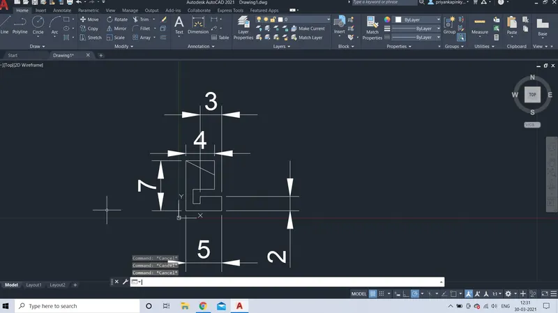
AIM: To create the P-9 geometry by using Relative coordinates method.
INTRODUCTION:
- Using relative coordinates method.
- start point of the P-9 geometry is (0,0).
PROCEDURE:
- Choose the Line command or tool.
- Line specify first point:(1,1) which is start point.
- Specify next point (or) undo:@Dx=1,DY=1(second point) and select the >> enter key.
- Specify next point (or) undo:@Dx=0,DY=7 (third point) and select the >> enter key.
- Specify next point (or) undo:@Dx=4,DY=0(fourth point) and select the >> enter key.
- Specify next point (or) undo:@Dx=0,DY=-4(fifthpoint) and select the >> enter key.
- Specify next point (or) undo:@Dx=-3,DY=0 (sixth point) and select the >> enter key.
- Specify next point (or) undo:@Dx=0,DY=-2(seventhpoint) and select the >> enter key.
- Specify next point (or) undo:@Dx=0,DY=1(seventhpoint) and select the >> enter key.
- Specify next point (or) undo:@Dx=3,DY=0(seventhpoint) and select the >> enter key.
- Specify next point (or) undo:@Dx=0,DY=-2(seventhpoint) and select the >> enter key.
- Specify next point (or) undo:@Dx=4,DY=0(seventhpoint) and select the >> enter key.
- Specify next point (or) [close/undo]
- There the given P-9 geometry is formed.
RESULT:
P-10
AIM: To create the P-10 geometry by using Relative coordinates method.
INTRODUCTION:
- Using relative coordinates method.
- start point of the P-9 geometry is (1,1).
PROCEDURE:
- Choose the Line command or tool.
- Line specify first point:(1,1) which is start point.
- Specify next point (or) undo:@Dx=0,DY=7(second point) and select the >> enter key.
- Specify next point (or) undo:@Dx=5,DY=0 (third point) and select the >> enter key.
- Specify next point (or) undo:@Dx=0,DY=-4(fourth point) and select the >> enter key.
- Specify next point (or) undo:@Dx=-3,DY=0(fifthpoint) and select the >> enter key.
- Specify next point (or) undo:@Dx=0,DY=-3 (sixth point) and select the >> enter key.
- Specify next point (or) undo:@Dx=-2,DY=0(seventhpoint) and select the >> enter key.
- Specify next point (or) undo:@Dx=3,DY=0(seventhpoint) and select the >> enter key.
- Specify next point (or) undo:@Dx=0,DY=2(seventhpoint) and select the >> enter key.
- Specify next point (or) undo:@Dx=-3,DY=0(seventhpoint) and select the >> enter key
- Specify next point (or) [close/undo] .
- There the given P-9 geometry is formed.
RESULT:
MONO PITCH
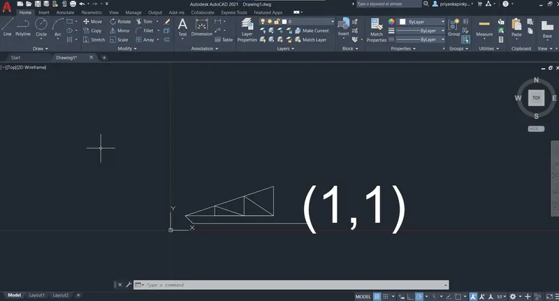
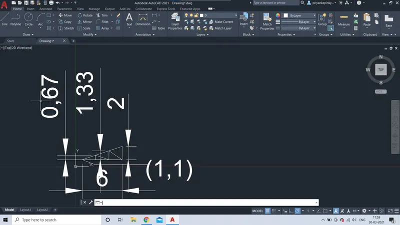
AIM: To draw the mono pitch truss using any one method of coordinate systems.
INTRODUCTION:
- A mono pitch truss has a single rafter and is a right angle truss used to form lean-to roofs or single pitched roofs.
PROCEDURE:
- First create a new file from aplication menu>> select new file and set units.
- Then choose line command from tool bar.
- Here, I use to draw the mono pitch truss by relative coordinate system method.
- Then specify the first point (1,1).
- Specify next point (or) undo:@Dx=6,DY=0(second point) and select the >> enter key.
- Specify next point (or) undo:@Dx=0,DY=2 (third point) and select the >> enter key.
- Specify next point (or) undo:@Dx=3,DY=1(fourth point) and select the >> enter key.
- Specify next point (or) undo:@Dx=0,DY=1.667(fifthpoint) and select the >> enter key.
- Specify next point (or) undo:4,1 and next point as 5,1 .
- Specify next point (or) undo:@Dx=0,DY=1.333 and select the >> enter key.
- Specify next point (or) [close/undo].
- Therefore, the mono pitch truss has drafted by given dimensions.
RESULT:
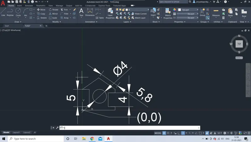
PROFILE WOOD
AIM: To create a profile wood of the given dimensions using any coordinates methods.
INTRODUCTION:
- Create a new file using application menu.
- Sets units using tool bar or menu bar or using commands.
PROCEDURE:
- Choose line command from tool bar.
- Here, I use to draw the profile wood by relative coordinate system method.
- Then specify the first point (0,0).
- Specify next point (or) undo:@Dx=0,DY=1(second point) and select the >> enter key.
- Specify next point (or) undo:@Dx=2,DY=0 (third point) and select the >> enter key.
- Specify next point (or) undo:@Dx=0,DY=5(fourth point) and select the >> enter key.
- Specify next point (or) undo:@Dx=-2,DY=0(fifthpoint) and select the >> enter key.
- Specify next point (or) undo:@Dx=5.8<35 select the >> enter key.
- Specify next point (or) undo:@Dx=5.8<325 and select the >> enter key.
- Specify next point (or) undo:@Dx=2<180 and select the >> enter key.
- Specify next point (or) undo:@Dx=4<270 and select the >> enter key.
- Specify next point (or) undo:@Dx=2<0 and select the >> enter key.
- Specify next point (or) undo:@Dx=1<270 and select the >> enter key.
- Specify next point (or) [close/undo].
RESULT:
QUEEN POST TRUSS
AIM: To create a queen post truss of the given dimensions using any coordinates methods.
INTRODUCTION:
- Create a new file using application menu.
- Sets units using tool bar or menu bar or using commands.
PROCEDURE:
- Choose line command from tool bar.
- Here, I use to draw the profile wood by relative coordinate system method.
- Then specify the first point (1,1).
- Specify next point (or) undo:@Dx=0,DY=4(second point) and select the >> enter key.
- Specify next point (or) undo:@Dx=7,DY=0 (third point) and select the >> enter key.
- Specify next point (or) undo:@Dx=0,DY=-4(fourth point) and select the >> enter key.
- Specify next point (or) undo: 1,5
- Specify next point (or) undo:@Dx=5<45 select the >> enter key.
- Specify next point (or) undo:@Dx=5<315 and select the >> enter key.
- Specify next point (or) undo: 4.5,5
- Specify next point (or) undo: 7,6 and 7,5.
- Specify next point (or) [close/undo].
RESULT: