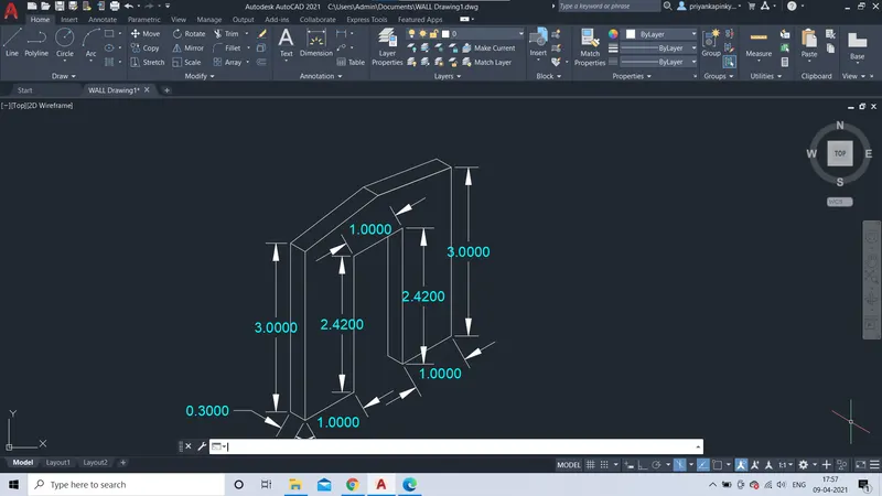
Creating a Floor plan, Footing detail and Isometric view using AutoCad
AIM: To create the cross section of Load Bearing Wall over spread footing using AutoCad.
INTRODUCTION:
- Create a new file and set units
- In the command prompt type 'un'
- Units > Drawing units > length type ( change the length accordingly ) > ok
PROCEDURE:
- Select the line tool from ribbon tab, the command prompt shows " specify the first point" as (8,4).
- Then the command states that to enter the next point or [undo] :
- Specify the next point or [undo]:0.90
- Specify the next point or [undo]:0.25
- Specify the next point or [undo]:0.20(inward)
- Specify the next point or [undo]:0.40
- Specify the next point or [undo]:0.05(inward)
- Specify the next point or [undo]:0.40
- Specify the next point or [undo]:0.05
- Specify the next point or [undo]:0.60
- Specify the next point or [undo]:0.05
- Specify the next point or [undo]:1.00
- Specify the next point or [undo]:0.30 (width)
- Specify the next point or [undo]:1.00
- Specify the next point or [undo]:0.60
- Specify the next point or [undo]:0.05(outward)
- Specify the next point or [undo]:0.40
- Specify the next point or [undo]:0.05
- Specify the next point or [undo]:0.40
- Specify the next point or [undo]:0.40
- Specify the next point or [undo]:0.20(outward)
- Specify the next point or [undo] as (8,4), else click ' close' from the command prompt.
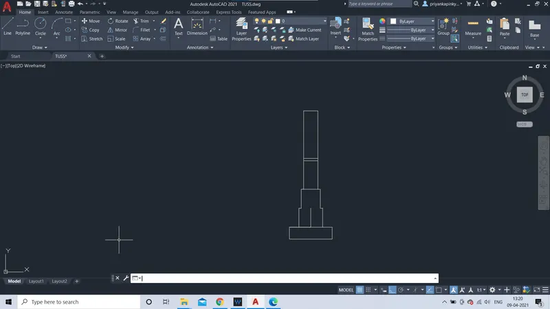
- specify the next point or [undo] :1.15 ( distance/ length) and 0.15 (width) below the ground level.
- Create the 3 steps beyond the bearing wall.
- Specify the next point or [undo]:0.30 (fall of the steps).
- Specify the next point or [undo]:0.15 (rise of the steps)and click 'close' from the command prompt.
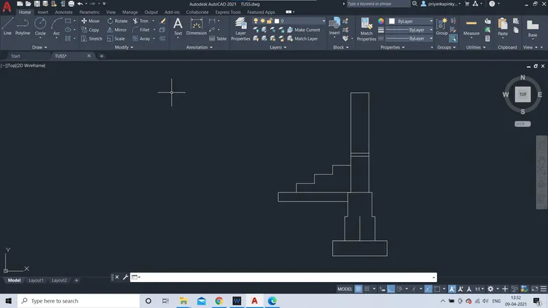
RESULT:
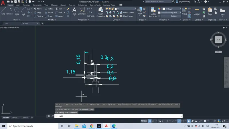
AIM: To create the cross section of the Isolated footing.
INTRODUCTION:
- Create a new file and set units
- In the command prompt type 'un'
- Units > Drawing units > length type ( change the length accordingly ) > ok
PROCEDURE:
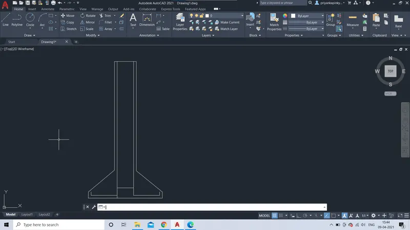
- Select the line tool from ribbon tab, the command prompt shows " specify the first point" as (3,2).
- Then the command states that to enter the next point or [undo] :
- Specify the next point or [undo]:1.00
- Specify the next point or [undo]:0.15
- Specify the next point or [undo]:0.25
- Specify the next point or [undo]:1.60
- Specify the next point or [undo]:0.04
- Specify the next point or [undo]:0.24
- Specify the next point or [undo]:0.04
- Specify the next point or [undo]:1.60
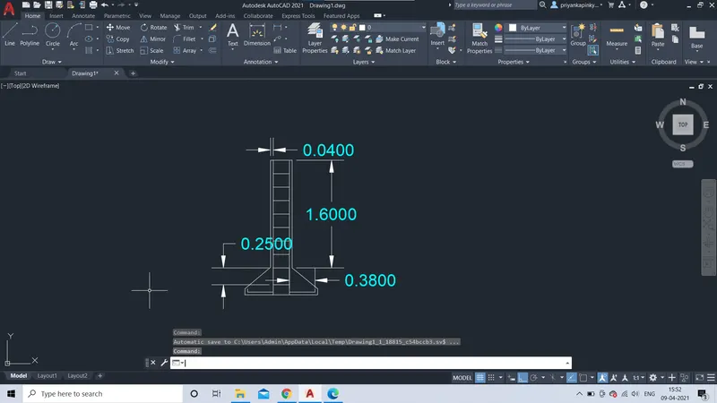
- Specify the next point or [undo]:0.38 ( create Reinforcement in isolated footing using line tool).
- provide offset using offest tool from ribbon tab.
- specify the offset distance as: 0.02 for bracings.
- Specify the next point or [undo/close]: C
RESULT:
AIM: To create a line diagram of a Bedroom Building.
INTRODUCTION:
- Create a new file and set units
- In the command prompt type 'un'
- Units > Drawing units > length type ( change the length accordingly ) > ok
PROCEDURE:
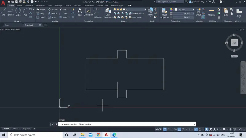
- Select the line tool from ribbon tab, the command prompt shows " specify the first point" as (3,2).
- Then the command states that to enter the next point or [undo] :
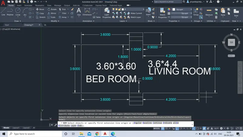
- Specify the next point or [undo]:3.60
- Specify the next point or [undo]:0.90
- Specify the next point or [undo]:1.00
- Specify the next point or [undo]:0.90
- Specify the next point or [undo]:4.20
- Specify the next point or [undo]:3.60
- Specify the next point or [undo]:4.20
- Specify the next point or [undo]:0.90
- Specify the next point or [undo]:1.00
- Specify the next point or [undo]:0.90
- Specify the next point or [undo]:3.60
- Specify the next point or [undo] as (3,2), else click ' close' from the command prompt.
RESULT:
AIM: To create the cross section Load Bearing Wall showing Foundation DetaIls.
INTRODUCTION:
- Create a new file and set units
- In the command prompt type 'un'
- Units > Drawing units > length type ( change the length accordingly ) > ok
PROCEDURE:
- Select the line tool from ribbon tab, the command prompt shows " specify the first point" as (3,2).
- Then the command states that to enter the next point or [undo] :
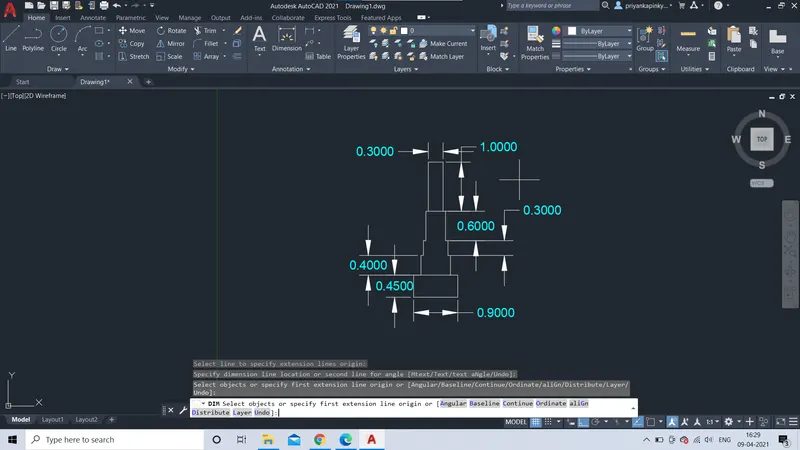
- Specify the next point or [undo]:0.90
- Specify the next point or [undo]:0.45
- Specify the next point or [undo]:0.15(inward)
- Specify the next point or [undo]:0.40
- Specify the next point or [undo]:0.05(inward)
- Specify the next point or [undo]:0.30
- Specify the next point or [undo]:0.05(inward)
- Specify the next point or [undo]:0.60
- Specify the next point or [undo]:0.05(inward)
- Specify the next point or [undo]:1.00
- Specify the next point or [undo]:0.30 (width)
- Specify the next point or [undo]:1.00
- Specify the next point or [undo]:0.60
- Specify the next point or [undo]:0.05(outward)
- Specify the next point or [undo]:0.30
- Specify the next point or [undo]:0.05(outward)
- Specify the next point or [undo]:0.40
- Specify the next point or [undo]:0.15
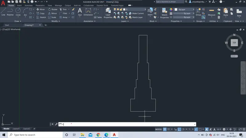
- Specify the next point or [undo] as (3,2),or else click ' close' from the command prompt.
RESULT:
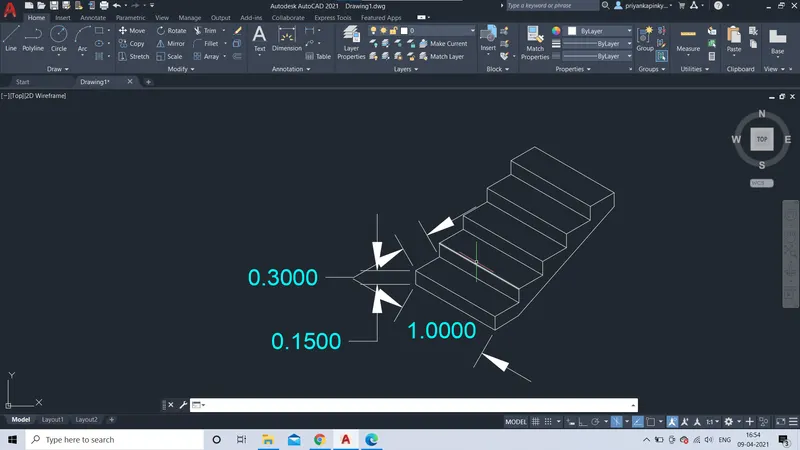
AIM: To create the Isometric view of steps using AutoCad.
INTRODUCTION:
- Create a new file and set units
- In the command prompt type 'un'
- Units > Drawing units > length type ( change the length accordingly ) > ok
- From the STATUS BAR (Bottom), select snap settings.
- In the snap settings off snap using F9 KEY or > snap mode and then off grid using F7 KEY or > gird mode.
- Then, Snap settings > snap type > isometric snap > ok.
PROCEDURE:
- Select the line tool from ribbon tab, the command prompt shows " specify the first point" as (3,2).
- Then the command states that to enter the next point or [undo] :
- Specify the next point or [undo]:
1.00 - Specify the next point or [undo]: < Isoplane top> 0.15 ( rise of the step)
- Specify the next point or [undo]: < Isoplane left> 0.30 ( fall of the step)
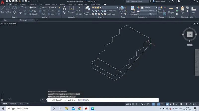
- By following the above steps, create the isometric of the 5 no of steps.
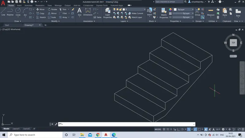
- Specify the next point or [undo/close]:C.
RESULT:
AIM: To create the Isometric View of Gable Wall using AutoCad.
INTRODUCTION:
- Create a new file and set units
- In the command prompt type 'un'
- Units > Drawing units > length type ( change the length accordingly ) > ok
- From the STATUS BAR (Bottom), select snap settings.
- In the snap settings off snap using F9 KEY or > snap mode and then off grid using F7 KEY or > gird mode.
- Then, Snap settings > snap type > isometric snap > ok.
PROCEDURE:
- Select the line tool from ribbon tab, the command prompt shows " specify the first point" as (5,3).
- Then the command states that to enter the next point or [undo] :
- Specify the next point or [undo]:
1.00 - Specify the next point or [undo]:
2.42 - Specify the next point or [undo]:
1.00 - Specify the next point or [undo]:
2.42 - Specify the next point or [undo]:
1.00 - Specify the next point or [undo]:
3.00 - Specify the next point or [undo]:
0.03 (width) - Specify the next point or [undo]:
3.00 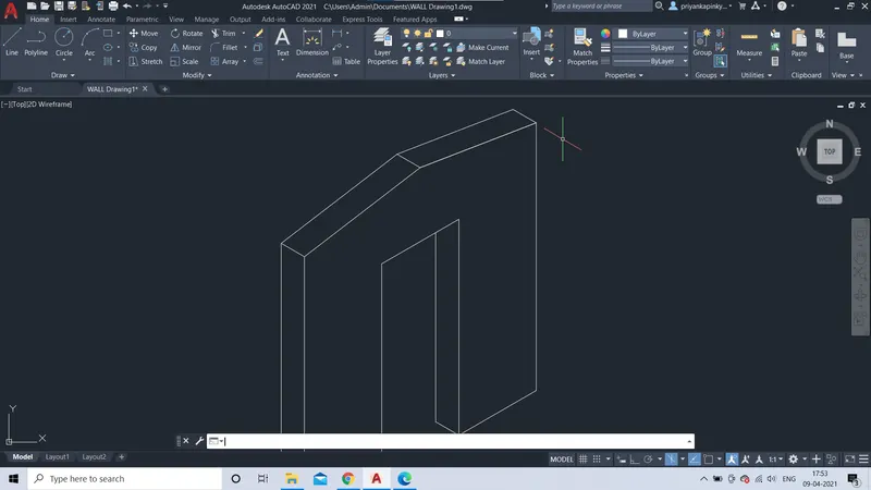
- Specify the next point or [undo/close] C.
RESULT: