Creation of Column Schedule and Drawing Template using AutoCad
AIM: To create a column schedule as given in the figure.
INTRODUCTION:
- Use of ANNOTATION COMMANDS such as Mtext command and textedit command to write the text in autocad.
- Use of Annoatation text scale factors in order to control the size of the text.
- Inorder to craete the schedule of the materials or the items of column schedule Line command was used where as tables can be directly created through the command TABLE where we give specify rows and column respecively.
PROCEDURE:
- First set units of the sheet of the drawing.
- Here the units where taken in mm.
- Let give the limits of the sheet such as left corner will be x,y (0,0) and right corner as x,y( 1000, 1000).
- In command prompt lets give zoom command, and click on zoom all,then start the drawing.
- Using line command specify the fisrt point of the coordinates as x,y( 25,25).
- Then specify the distance of 230mm length (right direction) .
- Specify the next point or [undo]:50mm width.
- Specify the next point or [undo]: 230mm length.
- Specify the next point or [undo/close]: close, which forms a rectangle.
- Then using the offset command, specify the offset distance as: 30>> enter.
- offset the vertical line of distance 30mm.
- Then again using the offset command, specify the offset distance of :40>> entrer.
- Which forms the 4 columns of the table.
- Using offset command, specify offset distance as: 5, 10 respectively; in order to create the requirement no's of rows in given table.
- Using MTEXT command give the text in table where ever required.
RESULT:
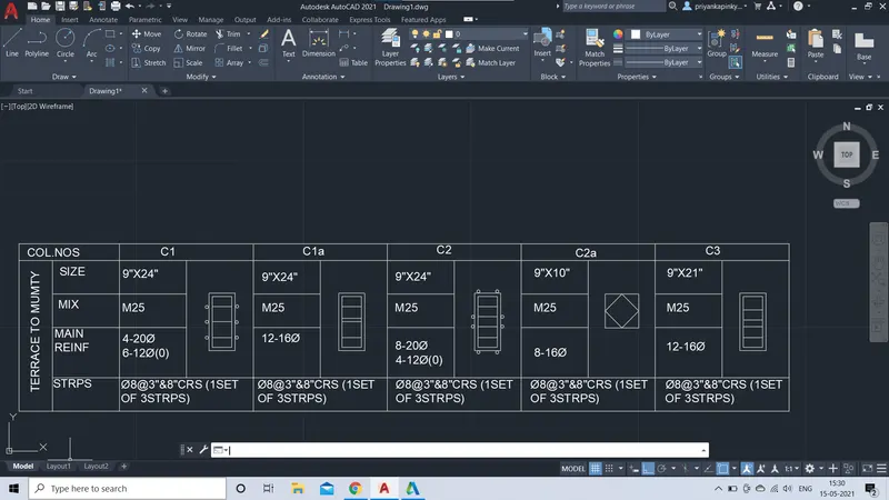
THEREFORE, THE GIVEN COLUMN SCHEDULE HAS BEEN CREATED AS SHOWN IN THE FIGURE.
2,
AIM: To create a window schedule as shown in the given figure.
INTRODUCTION:
- Use of ANNOTATION COMMANDS such as Mtext command and textedit command to write the text in autocad.
- Use of Annoatation text scale factors in order to control the size of the text.
- Inorder to craete the schedule of the materials or the items of column schedule Line command was used where as tables can be directly created through the command TABLE where we give specify rows and column respecively.
PROCEDURE:
- First set units of the sheet of the drawing.
- Here the units where taken in mm.
- Let give the limits of the sheet such as left corner will be x,y (0,0) and right corner as x,y( 1000, 1000).
- In command prompt lets give zoom command, and click on zoom all,then start the drawing.
- Using line command specify the fisrt point of the coordinates as x,y( 300,25).
- Then specify the distance of 150mm length (right direction) .
- Specify the next point or [undo]:40mm width.
- Specify the next point or [undo]: 150mm length.
- Specify the next point or [undo/close]: close, which forms a rectangle.
- Then using the offset command, specify the offset distance as: 20>> enter.
- offset the vertical line of distance 20mm.
- Then again using the offset command, specify the offset distance of :30>> entrer.
- Which forms the 3 columns of the table 30mm width.
- offset the vertical line of distance 40mm.
- Then again using the offset command, specify the offset distance of :40>> entrer.
- which forms the last column of the table.
- Using offset command, specify offset distance as: 5; in order to create 6 no's of rows of the given table.
- Using MTEXT command give the text in table where ever required.
RESULT:
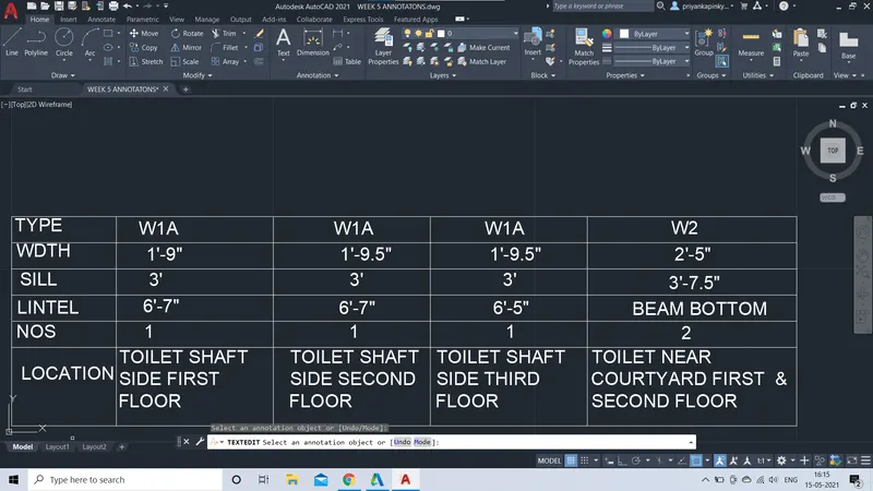
THEREFORE, THE GIVEN WINDOW SCHEDULE HAS BEEN CREATED AS GIVEN IN THE FIGURE.
3,
AIM: To create the drawing templates as shown in figure.
INTRODUCTION:
- Use of ANNOTATION COMMANDS such as Mtext command and textedit command to write the text in autocad.
- Use of Annoatation text scale factors in order to control the size of the text.
- Inorder to craete the schedule of the materials or the items of column schedule Line command was used where as tables can be directly created through the command TABLE where we give specify rows and column respecively.
PROCEDURE:
- First set units of the sheet of the drawing.
- Here the units where taken in mm.
- Let give the limits of the sheet such as left corner will be x,y (0,0) and right corner as x,y( 1000, 1000).
- In command prompt lets give zoom command, and click on zoom all,then start the drawing.
- Using line command specify the fisrt point of the coordinates as x,y( 500,25).
- Then specify the distance of 230mm length (right direction) .
- Specify the next point or [undo]:70mm width.
- Specify the next point or [undo]: 230mm length.
- Specify the next point or [undo/close]: close, which forms a rectangle.
- Then using the offset command, specify the offset distance as: 5>> enter.
- offset the vertical line of distance 5mm; as boundary line.
- Then again using the offset command, specify the offset distance of :80>> entrer.
- Which forms the 3 columns of the table 80mm width; of first box of the template.
- offset the vertical line of distance 40mm.
- Then again using the offset command, specify the offset distance of :40>> entrer.
- which forms the middle column of the template and specify an offset distance as: 10 on both sides of the column.
- Using offset command, specify offset distance as: 50; in order to create last column of given template.
- Use trim command where ever required for removing of unneccesary lines or segments.
- Using MTEXT command give the text in teplates to write the notes and details in the column of the given template where ever required.
RESULT:
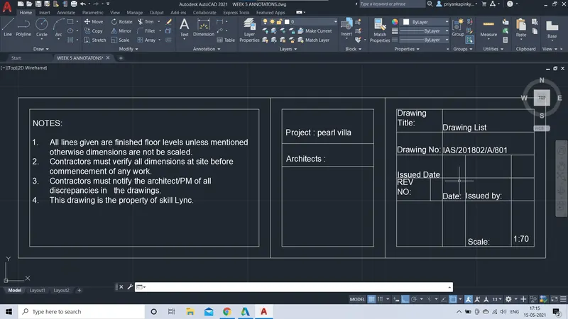
Therefore, the drawing template has been created as givenin the figure.
4,
AIM: To create the list of drawing schedule as shown in the figure.
INTRODUCTION:
- Use of ANNOTATION COMMANDS such as Mtext command and textedit command to write the text in autocad.
- Use of Annoatation text scale factors in order to control the size of the text.
- Inorder to craete the schedule of the materials or the items of column schedule Line command was used where as tables can be directly created through the command TABLE where we give specify rows and column respecively.
PROCEDURE:
- First set units of the sheet of the drawing.
- Here the units where taken in mm.
- Let give the limits of the sheet such as left corner will be x,y (0,0) and right corner as x,y( 1000, 1000).
- In command prompt lets give zoom command, and click on zoom all,then start the drawing.
- Using line command specify the fisrt point of the coordinates as x,y( 700,25).
- Then specify the distance of 110mm length (right direction) .
- Specify the next point or [undo]:265mm width.
- Specify the next point or [undo]: 110mm length.
- Specify the next point or [undo/close]: close, which forms a rectangle.
- Then using the offset command, specify the offset distance as: 20>> enter.
- offset the vertical line of distance 20mm; which forms the first column of the table.
- Then again using the offset command, specify the offset distance of :40>> entrer.
- Which forms 40mm width; which forms the secound column of the table.
- offset the vertical line of distance 50mm.
- Then again using the offset command, specify the offset distance of :50>> entrer.
- which forms the last column of the table.
- Using offset command, specify offset distance as: 5; in order to create 24 no's of rows of the given table.
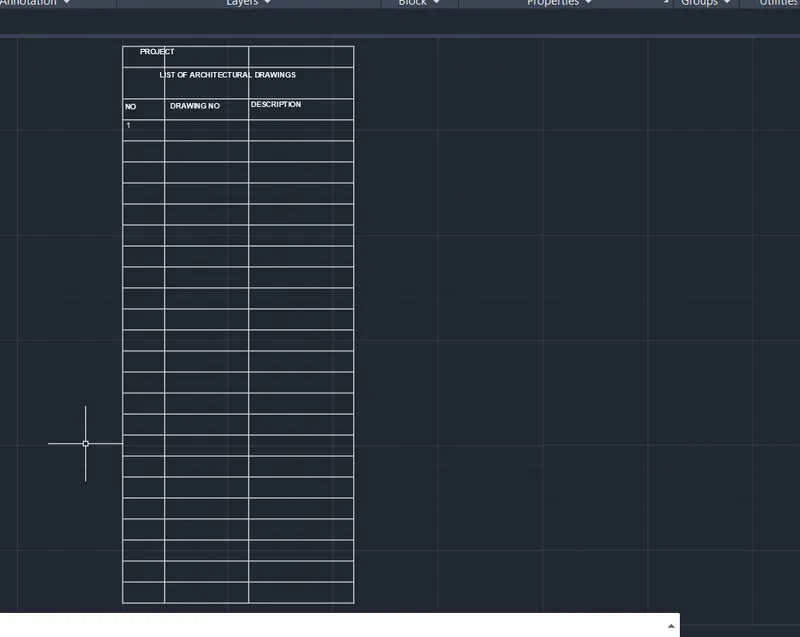
- Using MTEXT command give the text in table where ever required.
RESULT:
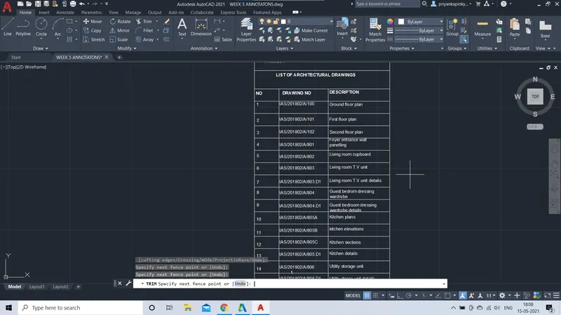
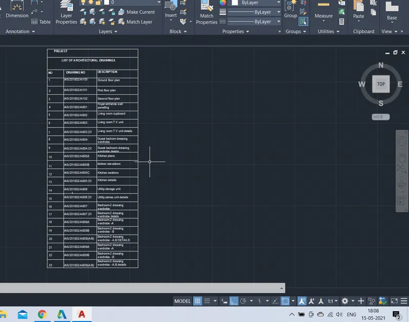
Therefore, the given list of the drawings has been drafted.
5,
AIM:To create the beam details of the given figure.
INTRODUCTION:
- Use of ANNOTATION COMMANDS such as Mtext command and textedit command to write the text in autocad.
- Use of Annoatation text scale factors in order to control the size of the text.
- Use of line comand and hatch command.
PROCEDURE:
- First set units of the sheet of the drawing.
- Here the units where taken in mm.
- Using line command; specify the first point : mannualy.
- specify the next point or[undo]: 90
- Using the offset command ; specify offset distance as: 30mm width of beam( taken manualy).
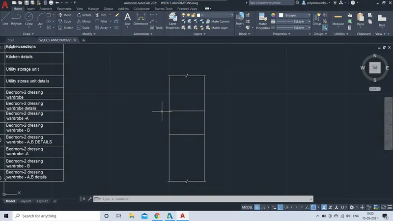
- Using hatch command , hatch the brick work portion and concrete portion as shown n figure.
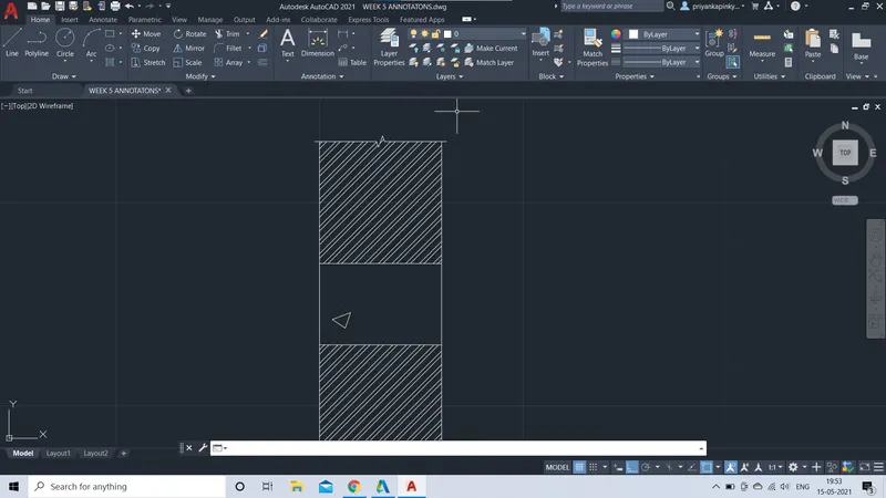
- Then, finally using breakline command ; specify the breakine at both edges of the beam.
- At last, specify the given text using MTEXT command.
RESULT:
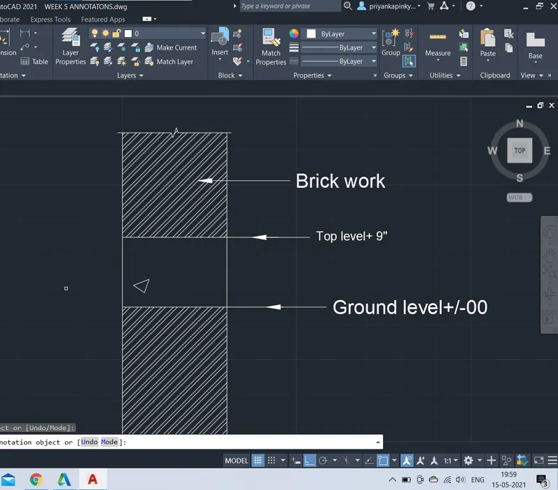
Therefore, the given beam details have been created has shown in the given figure.