Door Arm Rest Week 8 Challenge
AIM:
Creation of Door Arm Rest component through the given Class-A surface and perform draft analysis on the model. and ADD Thickness of 2.5mm.
OBJECTIVE:
The objective of the challenge is to create a Door Arm Rest design along the solid part body from class A surface in CATIA surface workbench and part design.
- To create a class B & C surface for the given component.
- To form a tooling axis.
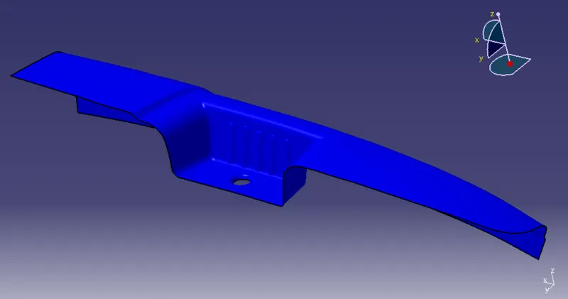
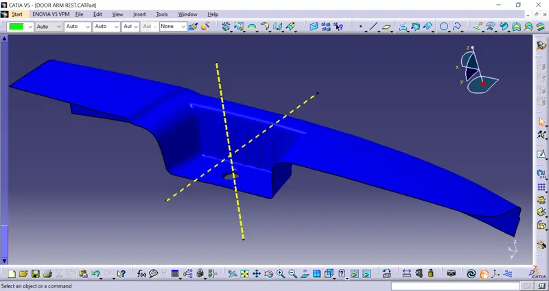
1. INPUT CLASS A SURFACE:
2. TOOLING AXIS DIRECTION:
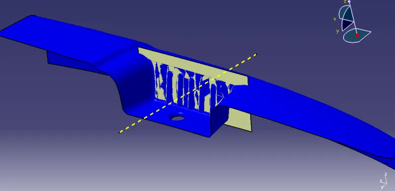
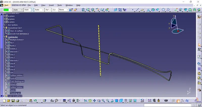
The Tooling Direction is basically the direction that the mold pulls apart. The mold is built in two separate pieces, basically. You have a Cavity side and you have the Core side. The Core pulls apart from the Cavity and that's the Dyeline or the Tooling Direction.
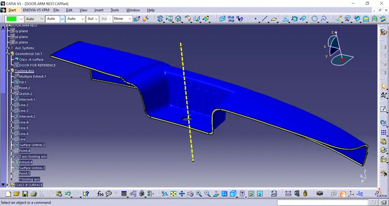
- analyzing the model visually to see the most efficient side suitable for the tooling axis from the image below image.
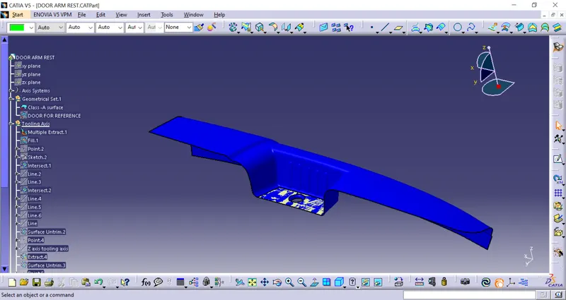
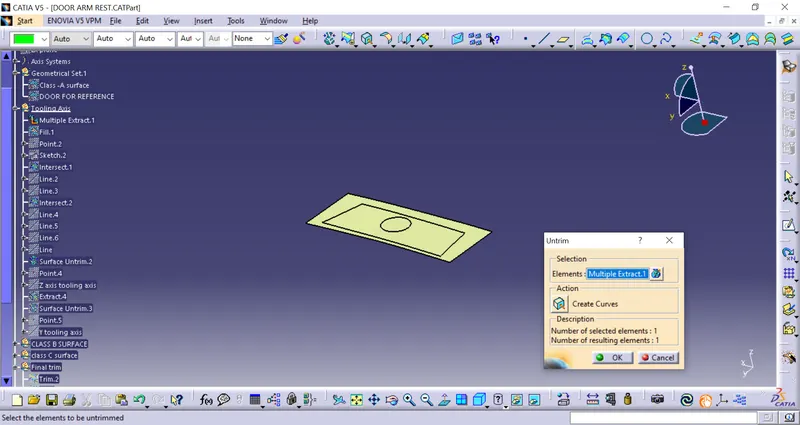
- Extract the surface of the class-A
- untrim the extracted surface
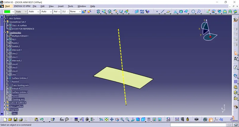
- make a point on the surface
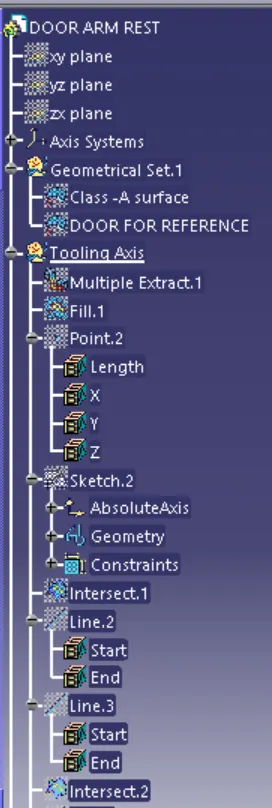
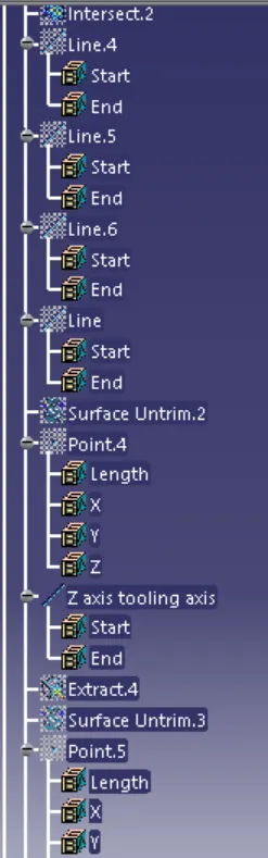
- create a line using Normal to surface along Z-axis
- creating a Y-axis tooling
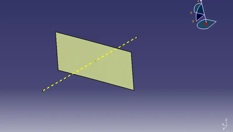
- create a point and create an axis line as per normal to the surface.
3. Class-B surface:
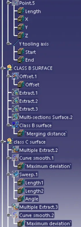
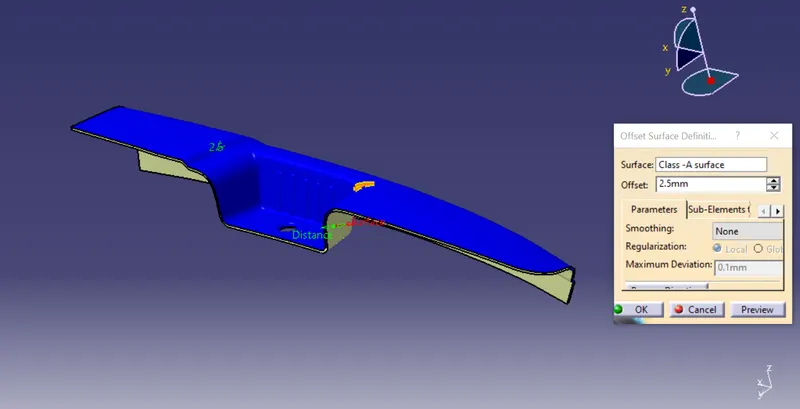
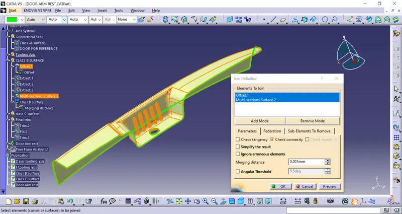
we directly offset the class A surface by 2.5mm to create a Class-B surface and do a Patchwork for some surface not occurs in Class-B.
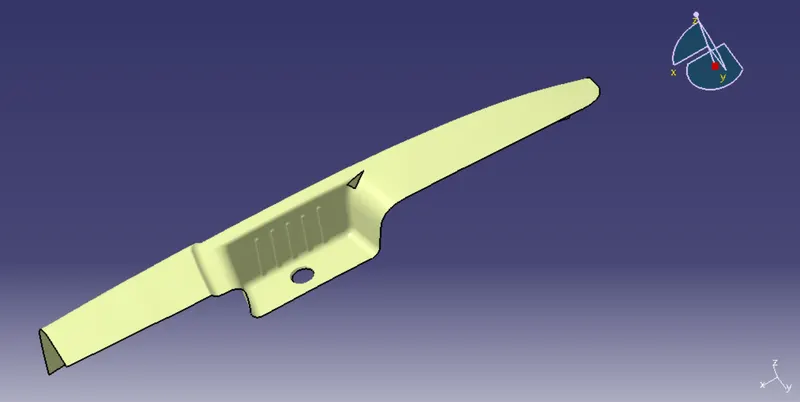
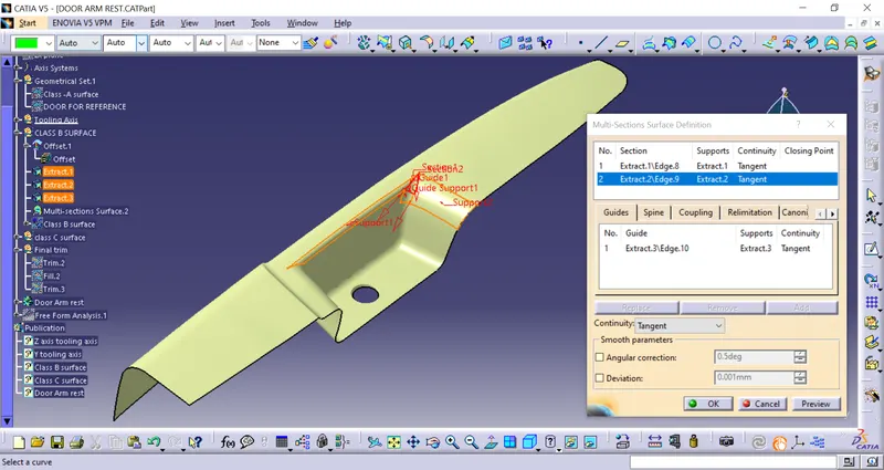
- Join the Multi-section surface to Class B offset to complete.
4. Class-C surface:
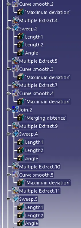
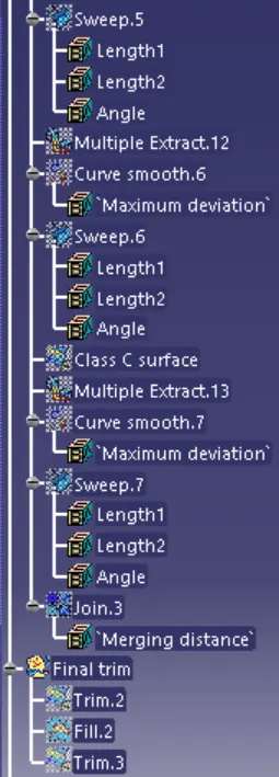
Now taking the boundary from the class-A surface and smoother the curve to avoid multiple sections.
Sweep the boundary from class A surface with help of sweep commend with reference of tooling axis and surface.
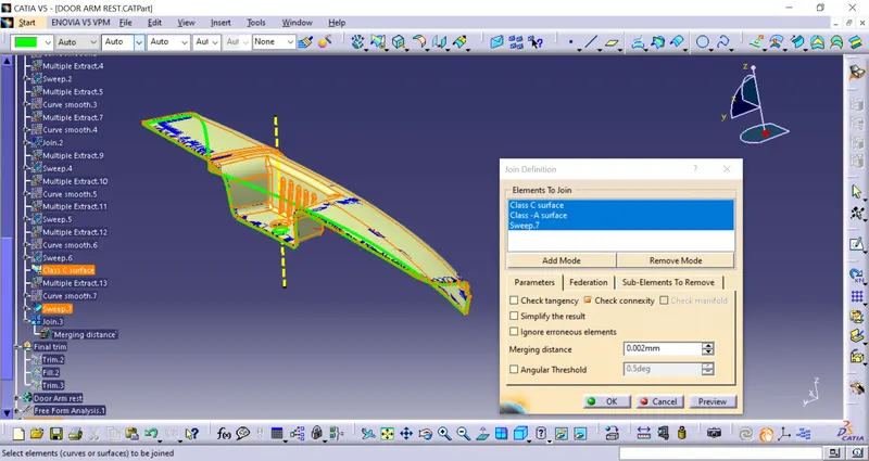
Joining the sweep with class A surface
- now trim the join with Class B to form a closed boundary surface.
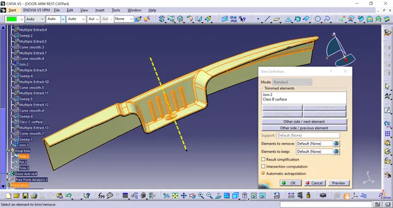
- After trimming the Switch Bezel surface will look like.
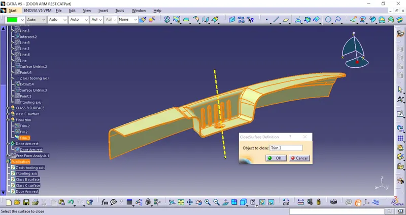
- The solid form of Class-A, B & C surface.
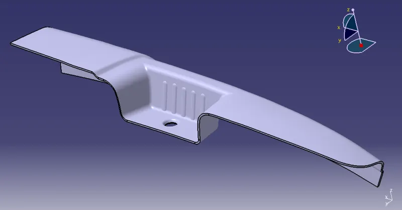
5. Drafting analysis on the solid part body:
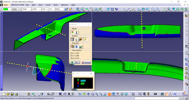
- After creating the solid body we will perform the draft analysis of the whole part body.
- First, change the parameter to material mode and then go to perform draft analysis Go to Insert > analysis > feature draft analysis.
- Click on the compass icon & align with the tooling axis.
Draft analysis of Class A surface Z-axis tooling direction
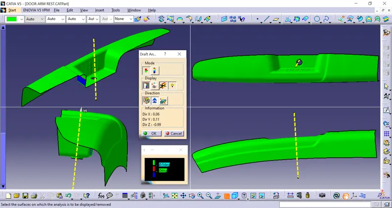
Draft analysis of Class A surface Y-axis tooling direction
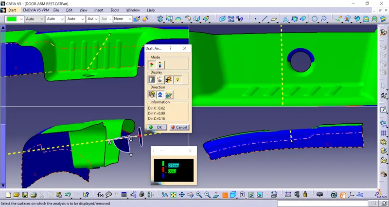
Draft analysis of Solid part Z-axis tooling direction
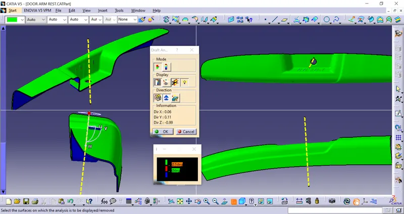
Draft analysis of Class A surface Y-axis tooling direction
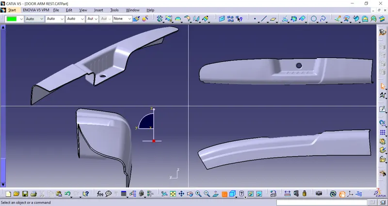
various orientations (Isometric, Front, Side, and Top View):
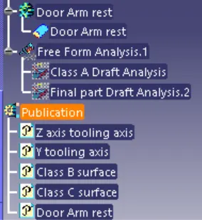
TREE STRUCTURE