Door Arm Rest Design using CATIA V5
DOOR ARM REST DESIGN USING CATIA V5
OBJECTIVE
To perform draft analysis on a Class-A Surface model of a automobile door arm rest and create a solid model from the Class A surface using B and C surfaces
INTRODUCTION
Manufacturing process: Injection Molding
Brief about the process
It is a manufacturing process used for the mass production of plastic components. It works by injecting molten material (plastic) into a mold. Under the application of heat and pressure, the material solidifies into the required shape. Once the product cools, it is ejected from the mold with the help of ejector pins.
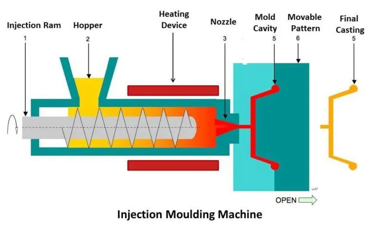
Terms in the injection molding process associated with this project
Draft
To facilitate easy removal of components from the mold, it is necessary to add a taper all along the surface with reference to the tooling direction. This taper is termed as a draft and its value ranges from 0.5 degrees to 3 degrees, with the latter being the most widely accepted norm.
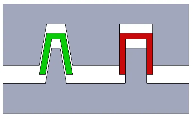
The Draft analysis command in CATIA enables to detect if the drafted part can be removed in an easy manner. This analysis is performed based on colour ranges identifying zones on the analyzed element where the deviation from the draft direction at any point, corresponds to specified values.
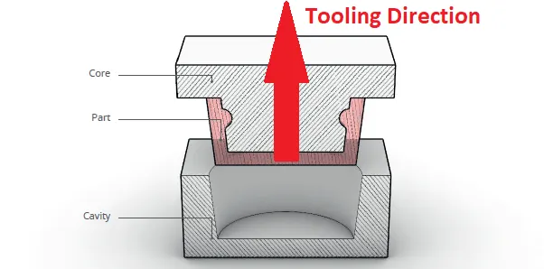
Tooling direction
The direction along which the core pulls apart from the cavity is termed as the Dyeline or the Tooling direction.
Undercut and Side core
An undercut is a feature in the part design that would prevent the part from releasing out of the mould (part of the mould cavity is undercut in such a way that it grips the moulded part).
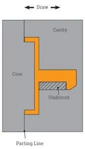
The purpose of side actions is to enable undercut geometry; in other words, to mould parts that could not otherwise be made in a straight-pull mould. In straight-pull injection moulding, the A-side and B-side of the mould open and the completed part can be removed by pulling it straight out of either side.
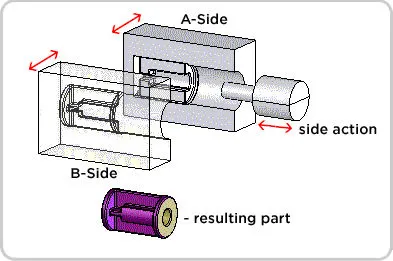
To release a part whose design includes undercuts, the mould surfaces that create the undercut geometry in the part must be pulled out of the part before it is ejected; otherwise the part will be stuck in the mould. A cam device in the mould is used to pull the side-action mould surfaces away from the undercut features allowing the part to be released from the mould.
Software : CATIA V5
CATIA (an acronym of Computer Aided Three-dimensional Interactive Application) is a multi platform software suite for CAD, CAM, CAE, PLM and 3D , developed by the French company Dassault Systèmes.
The version of CATIA used for this project is V5. For the target model, the features in the part and surface workbench were extensively used.
Target Model: Automobile door arm rest
In an automotive context, an arm rest serves the purpose of aiding the passengers in resting their arm. Arm rests can be found in various positions within the interior of an automobile. The door arm rest, which also holds storage bins and other small utilities have been chosen for this particular project
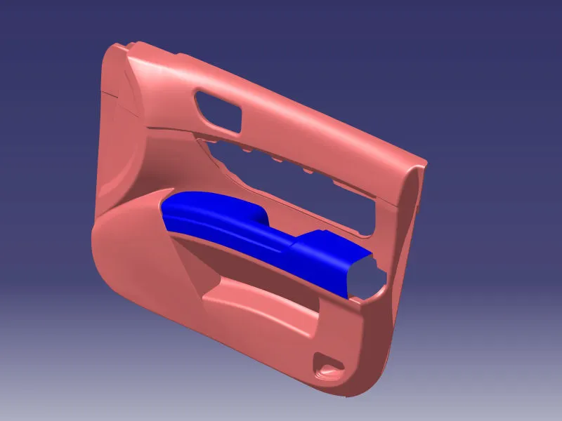 Fig: Door arm rest (Blue)
Terms in CAD associated with this project
Class-A Surfaces
The aesthetic/free-form surface which constitutes the visible outer layer of a component can be termed as a Class-A Surface. In this project, the Class-A surface of a door arm rest which is composed only of curvature continuous surfaces is used as the input for performing the draft analysis.
B and C Surfaces
The B surface forms the inner components and acts as a base for the Class-A surface. C surface connects the A and B surfaces and thereby provides a thickness for the final component
Tools in CATIA associated with this project
- Sketcher workbench: Point, Line, Intersect 3-D elements
- Part workbench: Close surface
- Surface workbench: Boundary, Extract, Multiple extract, Untrim, Extrapolate, Offset, Trim, Split, Join, Edge fillet, Curve smooth, Blend, Multi-sections surface, Fill
Methodology in CATIA associated with this project
Bisecting Line method
Since draft is measured with reference to a tooling axis, the first step after importing the model into CATIA was the creation of a tooling axis. To incorporate for tool clearances due to the presence of tapered surfaces in the part, the bisecting line method was used to create the tooling axis.
After converting the surface into a 2D profile using the Intersection command from the surface workbench, two inclined lines were created using the endpoints of the 2D curves which represented the tapered faces. Using a bisecting line type, a third line was created along the centre point which signified the coincidence of the tapered faces. This line was the required tooling axis for this component.
Draft Analysis
The draft analysis command in CATIA helps to detect whether the drafts provided in the model will facilitate easy removal of the component during manufacture.
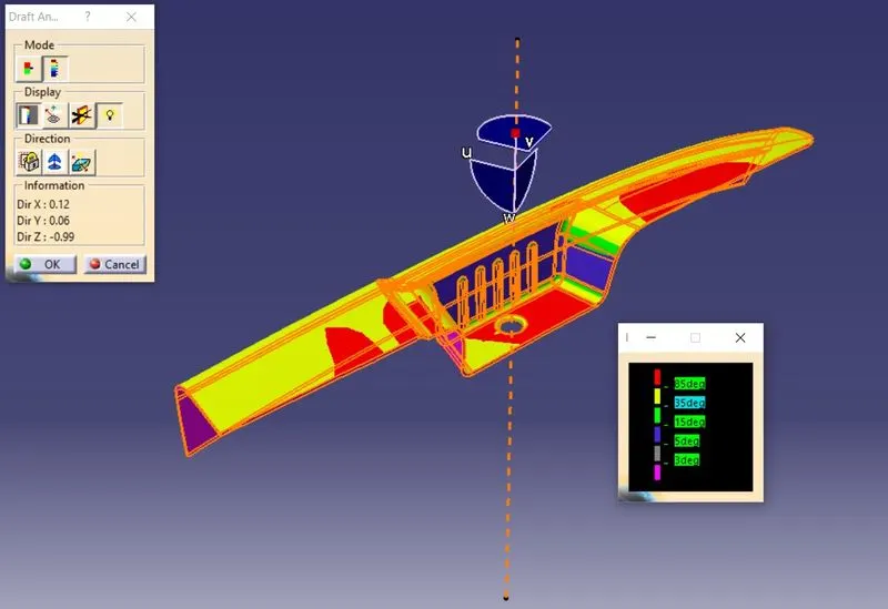
This analysis is performed based on colour ranges identifying zones on the analyzed element where the deviation from the draft at any point, corresponds to specified values.
-
When the draft angle value of the surface is equal or smaller than a graduated value, the color below the graduated value is applied
-
When the draft angle value of the surface is greater than the greatest graduated value, the color above this graduated value is applied
In this project, the required draft for all surfaces were chosen as 3 degrees and hence the quick mode option in draft analysis was chosen which incorporated two different colours for two input values.
B and C surface creation
The B surface was created by offsetting the Class-A surface and then extrapolating it to accommodate the entire area of the Class-A surface.
The C surface provided the thickness and acted as the joining surface between Class A and B surfaces.
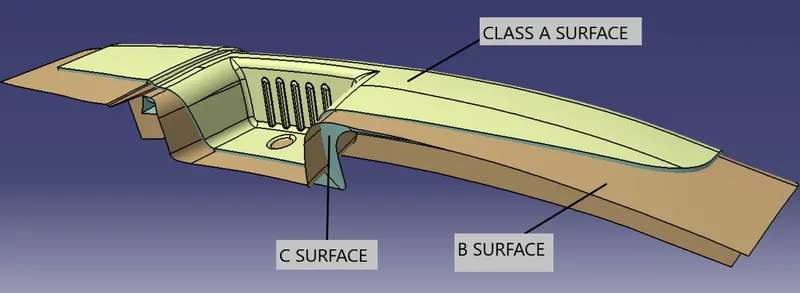
The Class A and C surfaces were made into a single surface using the Join command in the surface workbench. This was then trimmed (Trim tool) using the B surface to create the final component. The model was then converted into a solid using the Close Surface command.
OVERVIEW OF THE PROJECT
Flowchart of processes
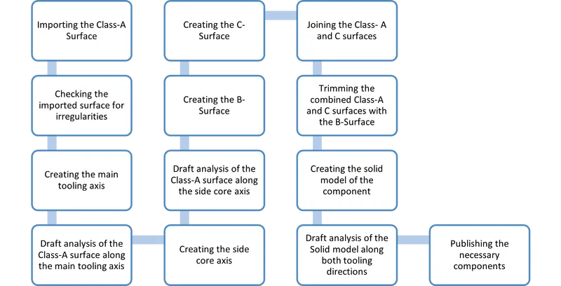
DETAILED PROCEDURE
1. Importing the Class-A Surface along with reference
- The Class-A surface model of the arm rest along with a reference model of a door was imported into the Catia workspace
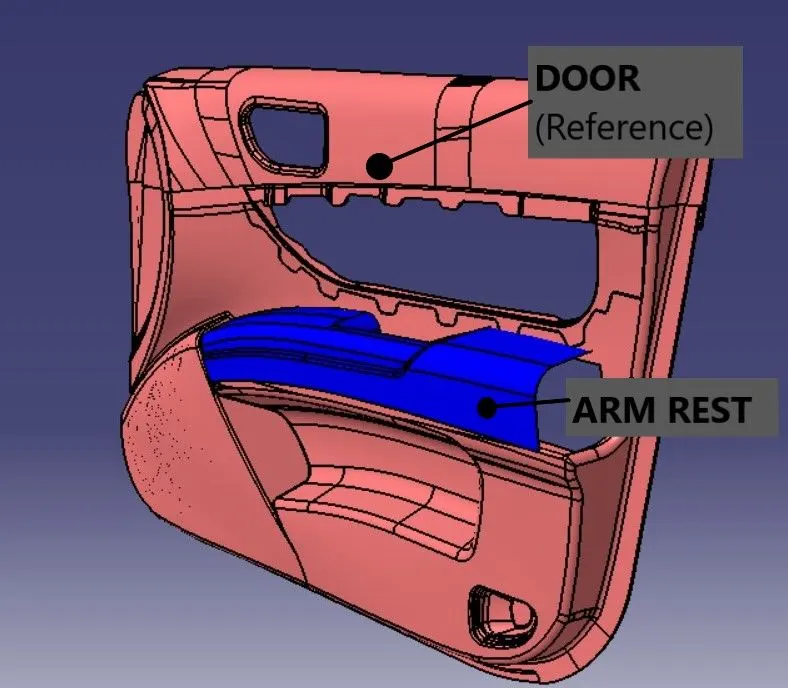 Fig1: Door and Arm rest
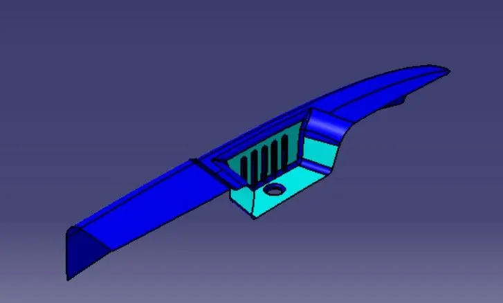 Fig2: Class-A Surface Model of Arm Rest
- Since the model was imported, a detailed check to detect surface irregularities was done using the Boundary tool
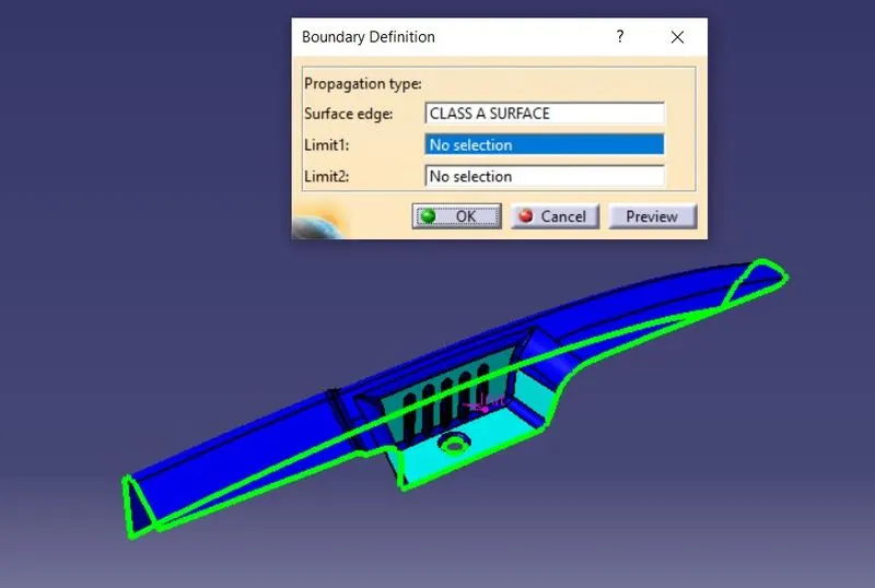 Fig3: Checking for surface irregularities using boundary tool
2. Creation of main tooling axis
- The first step towards checking the component for manufacturability was to conduct a draft analysis on the imported Class-A Surface
- To successfully perform a draft analysis, a proper tooling axis needed to be determined first, along which the mould halves separated
- Clearing the bin area of the arm rest needed special consideration due to the presence of inclined walls
- So, the hole in the bin was chosen as the base for construction of a dummy tooling axis
- The curves forming the hole was extracted and a surface was created from them using the Surface fill tool
- A point was created on this surface at its centre and an axis system was inserted into it
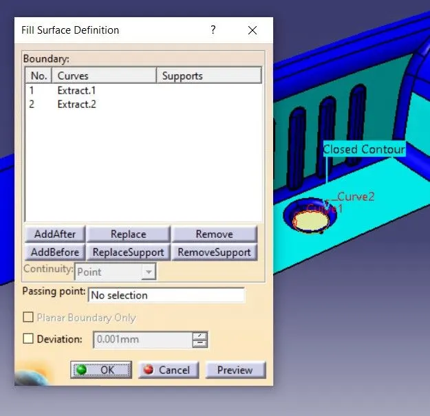 Fig4: Surface fill tool
- Using the point and the Z-direction as inputs, a straight line was constructed which was perpendicular to the base surface which was chosen as a dummy tooling axis
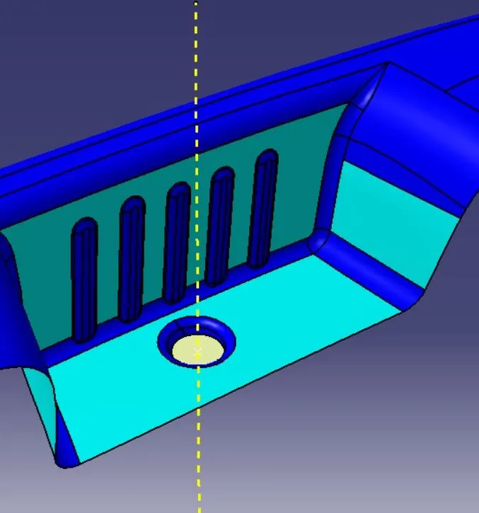 Fig5: Dummy Tooling axis
- Due to inclinations in the left and back walls of the bin, beyond the accepted draft conditions for this project, the tooling axis needed to be considered in such a manner that it incorporated both these values effectively
- To create a centre line through the coincidence of two lines the best method was to use the Bisecting line tool
- A new positioned sketch was created in the XZ plane using the 3D intersection of the Class-A surface with the XZ plane as a reference
- An inclined line was drawn on the left inclined curve which represented the wall and a line at 3 degree inclination was drawn, passing through the centre, which was chosen as the tool clearance in the X direction
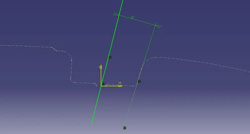 Fig6: Tool clearance (XZ Plane)
- A similar procedure was done for determining the tool clearance in the Y direction using a sketch in the YZ plane
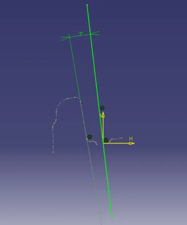 Fig7: Tool Clearance (YZ Plane)
- Using both these lines as reference, an bisecting line was created which was chosen as the Main Tooling axis for this model
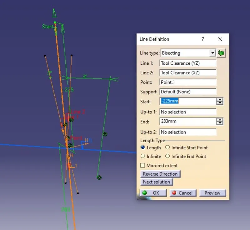 Fig8: Bisecting line method
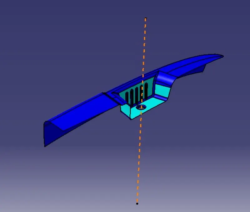 Fig9: Main Tooling Axis
3. Performing draft analysis with reference to the main tooling axis
- To check the component for manufacturability, a draft analysis needed to be done before proceeding to the subsequent stages
- Using the Feature Draft Analysis tool offered by CATIA, the performance of the model under a 3 degree draft condition was analysed
- The draft direction was chosen by dragging the compass and coinciding it with the tooling axis
- The quick analysis mode was chosen since the draft value chosen for this project was 3 degrees for all the surfaces of the component
- It was observed that the right wall was not clearing and hence it was determined that this model needed a side core to ensure proper mould parting
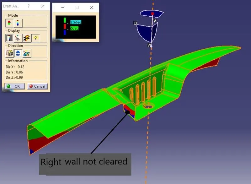 Fig10: Draft Analysis of the Class-A Surface along the main axis
4. Creating of Side core/Slider axis
- To create another axis which represented the direction of side core, a base surface needed to be selected
- The ribbed face of the bin was extracted using the Extract tool and a centre point was created on its middle
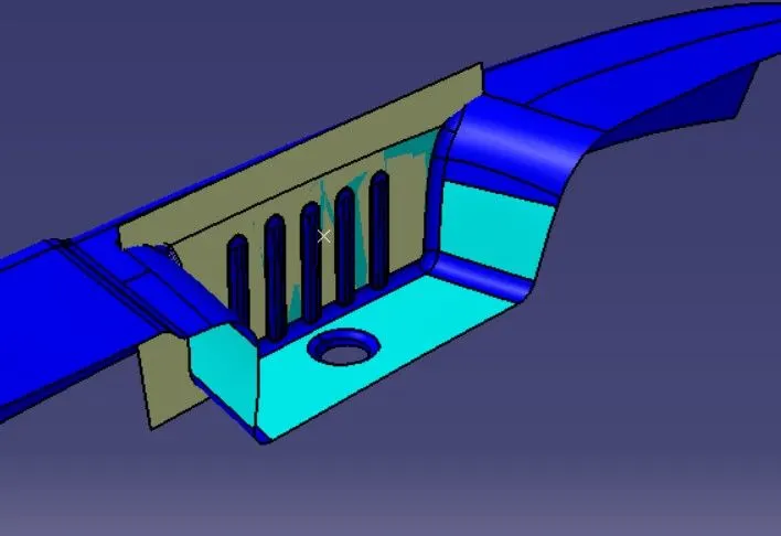 Fig11: Extracted face with centre point
- An axis system was also inserted into this face using the point as a reference
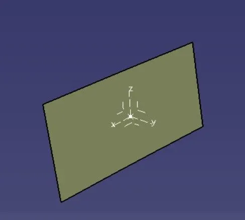 Fig12: Base surface and axis system for Side Core Axis
- A new positioned sketch was created on the YZ plane and the intersection curve of the Class-A surface with the YZ plane was used as a reference
- From the base of this sketch a line was drawn which passed through the centre point, inclined to the base at an angle of 3 degree which represented the required draft for this project
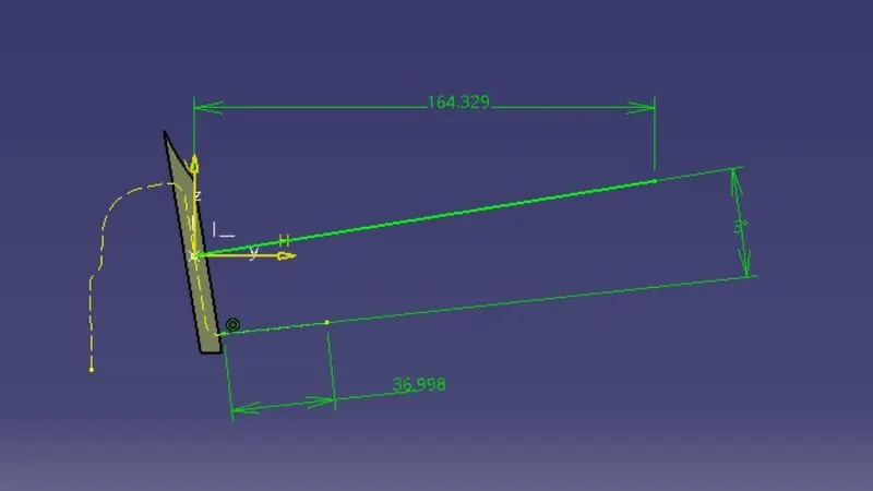 Fig13: Creating the side core axis
- This line was chosen as the side core axis for this model
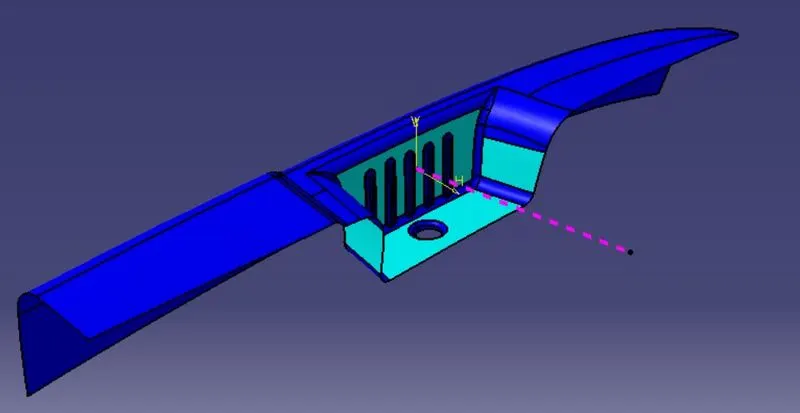 Fig14: Side Core axis
5. Performing draft analysis with reference to the side core axis
- A new draft analysis was done on the Class-A surface with reference to the side core axis to check for proper mould parting
- Upon adjusting the compass in an inclined position with reference to the side core axis, it was observed that the previous tool clearance issue faced by the right wall of the bin was resolved
- This proved that the tooling direction chosen for the side core was correct and the Class-A surface model followed all manufacturing criteria
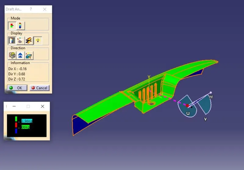 Fig15: Draft analysis of the Class-A Surface along the Side Core Axis
6. Creation of B Surface
- Once the analysis on the class-A model was done the next step was to create the B-Surface for the model
- The Class-A Surface features were analysed and according to the B-surface creation procedure followed in this project, different regions were selected and assigned different colours and appropriate names
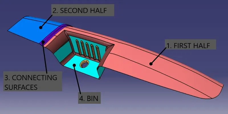 Fig16: B-Surface creation procedure
- FIRST HALF:
- This was the first area chosen to be created into a B-Surface
- Two planar surfaces were chosen and extracted from the Class-A surface
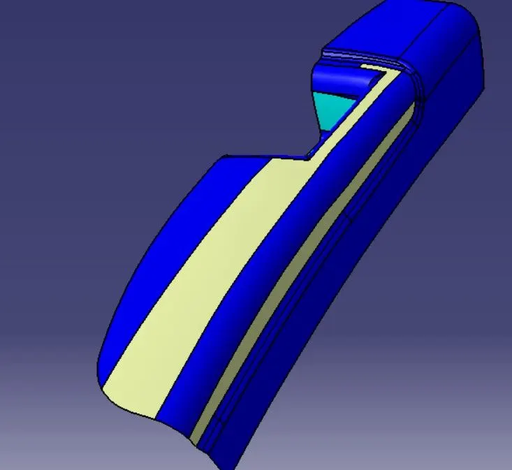 Fig17: Extracted surfaces
- The top surface was untrimmed using the Untrim tool and both these surfaces were modified using the Extrapolate tool
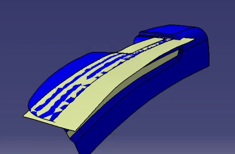 Fig18: Untrimmed top surface
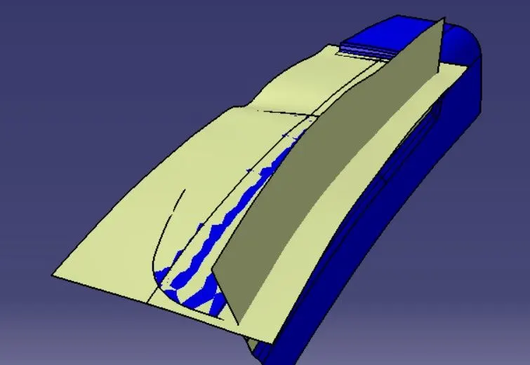 Fig19: Extrapolated surfaces
- These surfaces were then offsetted using the Offset surface tool to 2.5 mm which was the required thickness standardized for this project
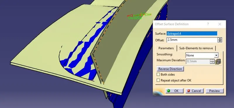 Fig20: Offsetted surfaces
- To join both these surfaces and to remove extended portions, the Trim surface tool was used
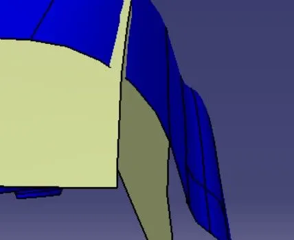 Fig21: Trimmed surfaces
- By extracting the filleted portion between these surfaces in the Class-A model and untrimming this extracted surface, the fillet value was measured, which in this case was 17mm
- Since the offestted B-surfaces incorporated the required thickness of 2.5mm, this value was subtracted from the determined value of 17mm (=14.5mm) before applying the fillet for the previously trimmed surfaces
- This process was followed throughout this project for applying fillets with addition employed whenever the offestted surface was above the Class-A Surface
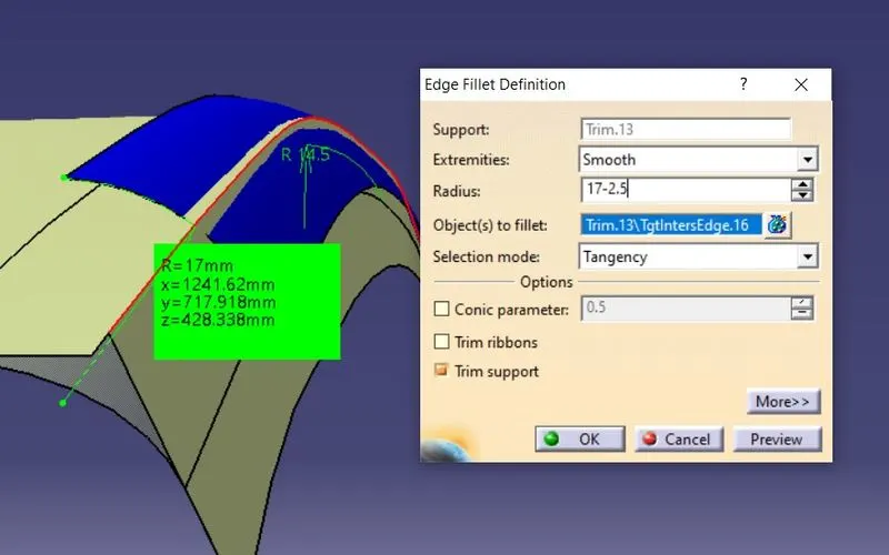 Fig22: Applying fillets to the first half B-Surface
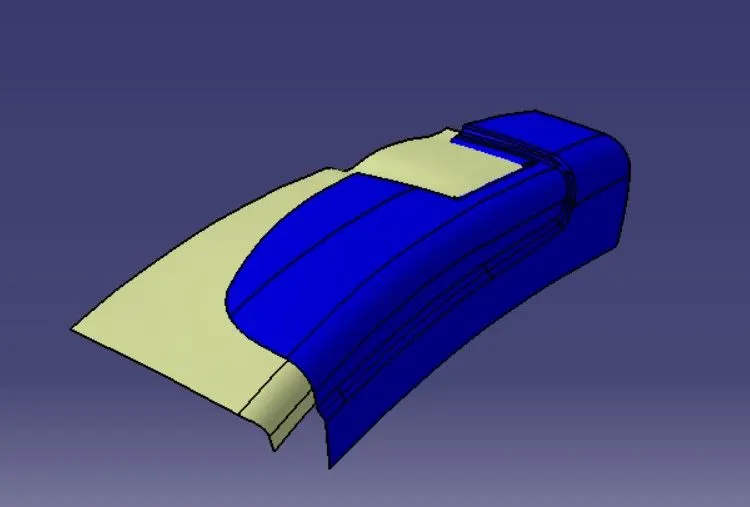 Fig23: First Half B-Surface
- SECOND HALF:
- The second half was constructed in a similar manner as the first half
- The surfaces on the side and top were first extracted, offsetted, extrapolated and then trimmed (Image below. Clockwise from top: Surface extract, extrapolate, trim, fillet)
- A fillet was added with appropriate value at the sharp trimmed corner
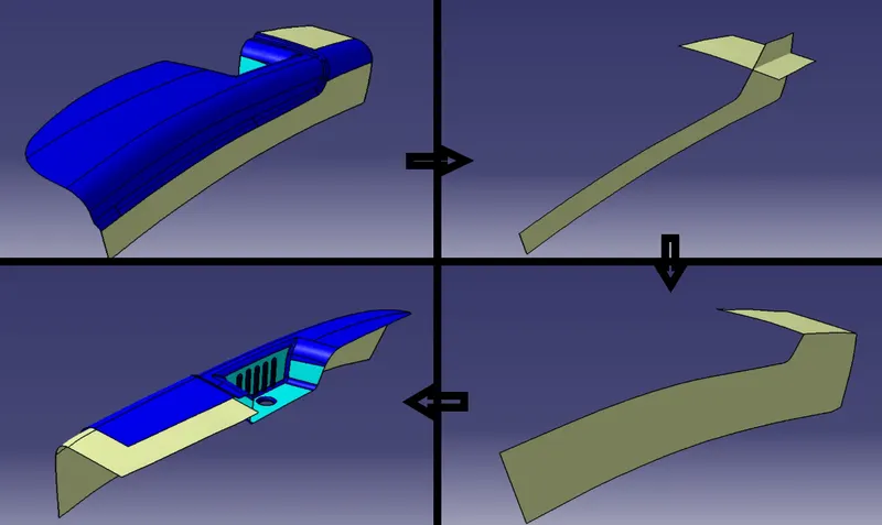 Fig24: Construction of second half B-Surface
- CONNECTING SURFACE:
- The next construction was that of the narrow surface which connected both first and second halves of the B-Surface
- The procedure chosen for this construction was creating a sketch and sweeping it along the required direction
- A point was created at the intersection of two fillets in the connecting region of the Class-A Surface and an axis system was inserted into it
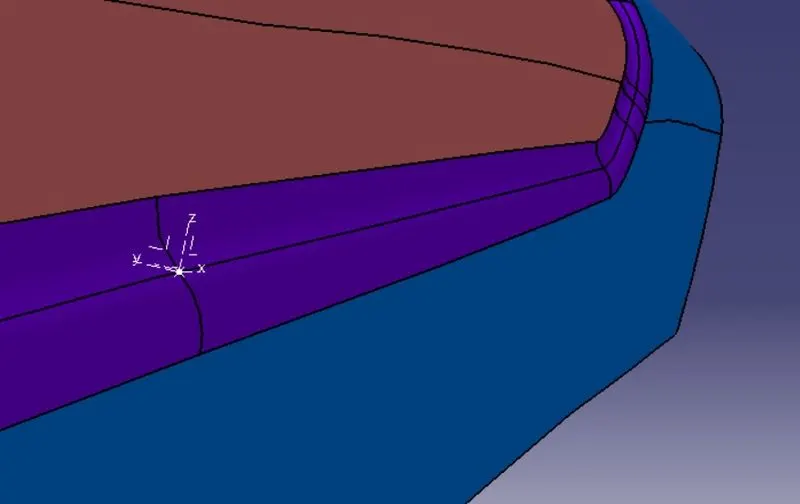 Fig25: Base point and axis system for construction of connecting surfaces
- Using the 3D intersection curve of the Class-A surface with the YZ plane as a reference in a new positioned sketch, a line was drawn tangent to the fillet
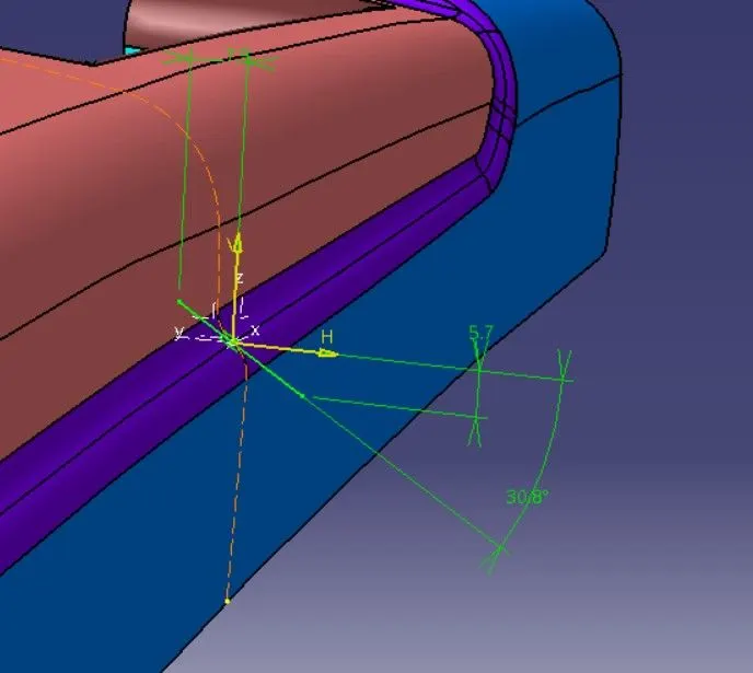 Fig26: Sketch (profile) for sweep
- The joining line formed by the two fillets in the Class-A surface was extracted and smooth curve tool was used to produce a continuous curvature
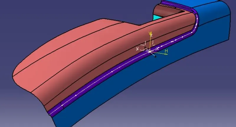 Fig27: Path for sweep
- Using the previous sketch and the smooth curve, a swept surface was created using the Sweept surface tool
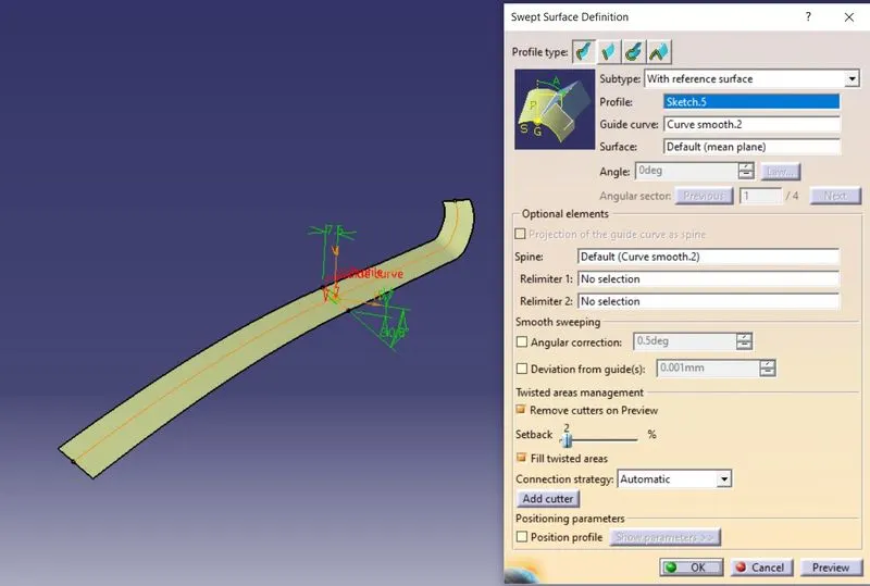 Fig28: Swept surface
- A surface was then extracted from the top connecting area of the Class-A surface which was untrimmed and extrapolated for use in B-surface
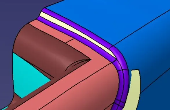 Fig29: Surface extract
- Both the extracted and swept surfaces were then offsetted
- To produce a smooth transition between surfaces, an inclined line was drawn on the extracted surface which was used to remove a portion of the surface using the Split surface tool
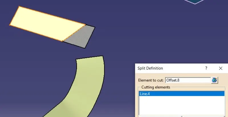 Fig30: Split surface
- A transitioning surface was created between these surface components using the Blend tool
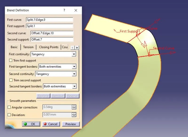 Fig31: Blend
- All the surface components were then joined together using the Join tool to produce a single surface
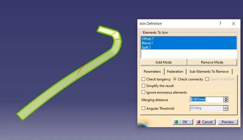 Fig32: Join tool
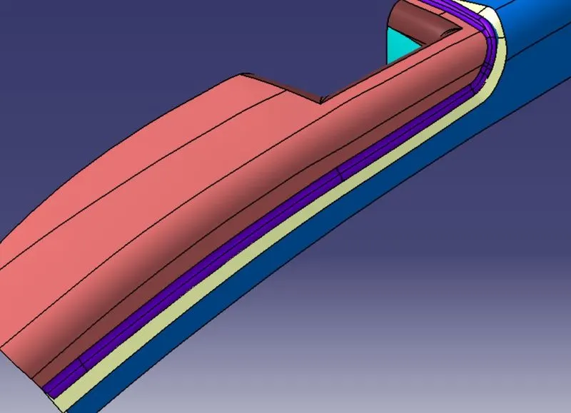 Fig33: Connecting surface
- INITIAL TRIM:
- Gaps were observed between the B-surface components
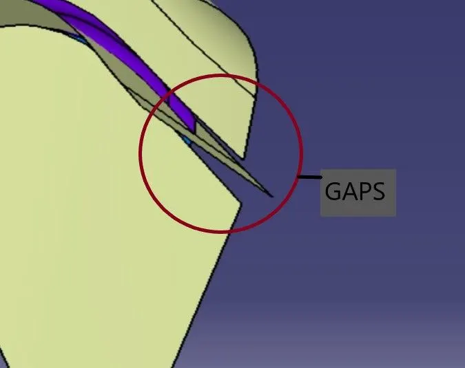 Fig34: Gaps
- By extrapolating the first and second half of the B-surface, the gaps were nullified
- The first half and the connecting surface were first trimmed together and then, together, they were used to trim the second half thereby joining all three surfaces
- Appropriate fillets were added along the joining curve of the connecting surface
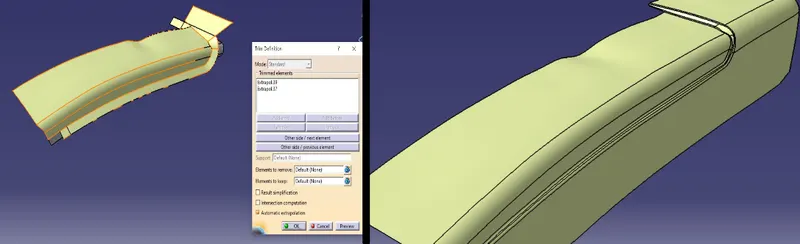 Fig35: Initial trim
- BIN:
- The bin surfaces were extracted from the Class-A surface model
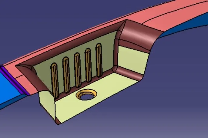 Fig36: Extracted surfaces
- These surfaces were then untrimmed, extrapolated and then offsetted
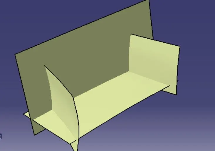 Fig37: Extrapolated bin surfaces
- These surfaces were trimmed to achieve the required shape of the bin
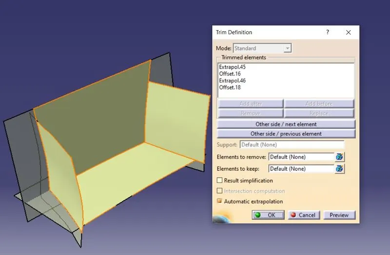 Fig38: Trimmed B-surfaces of the bin
- These surfaces were then trimmed with the existing B-surface features to create a single component
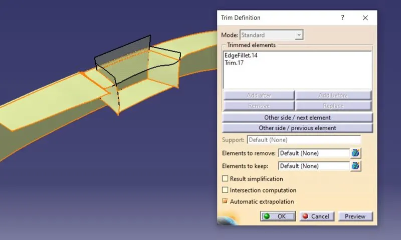 Fig39: Final trim of B-surface
- Appropriate fillets were added to the sharp corners to complete the construction of B-surface
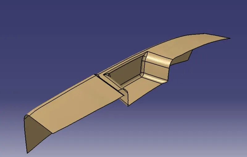 Fig40: B-Surface of the arm rest
7. Creation of C-Surface
- The edges of the Class-A surface was used as a refrence for the creation of C-surface
- The lower back edge of the Class-A surface was extracted and smooth curve tool was applied to create a continuous curvature
- Using the Class-A surface as a reference and the smooth curve as the guide curve a swept surface was created using the Swept surface tool with a 90 degree inclination to the edges and facing inwards
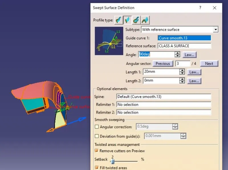 Fig41: Swept surface (90degree)
- Using the main tooling axis as the draft direction and appropriate curves, three more surfaces were created along the front edges with a 3 degree inclination (outward draft direction)
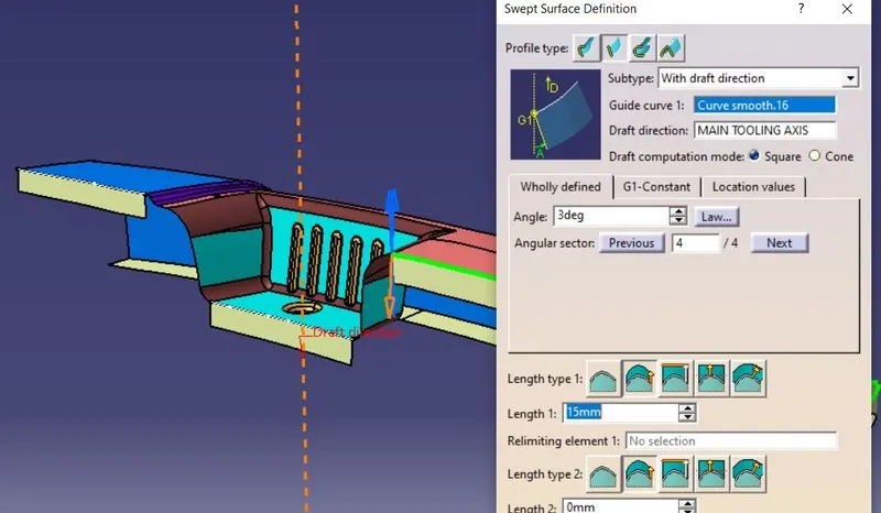 Fig42: Swept surface (3 degree)
- To create the surfaces connecting these three halves, the Multi sections surface tool was used
- To ensure smooth transition, the surfaces were first split using an inclined line
- Using the inclined lines as the section, with the surfaces as the support and the curved edges (smooth) as the guide curve, the joining surfaces were created using the multi sections surface tool
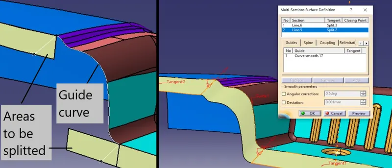 Fig43: Creating multi sections surface
- This procedure was repeated to create joining surfaces all around the component
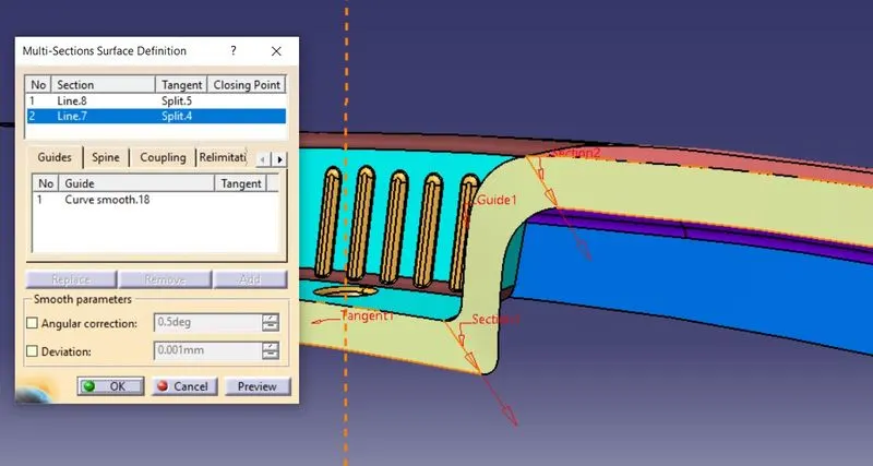 Fig44: Multi section surface
- For the left edges, the irregular transitions were removed a guide curve was created by splitting the boundary using a point before joining the gap using multi sections surface tool
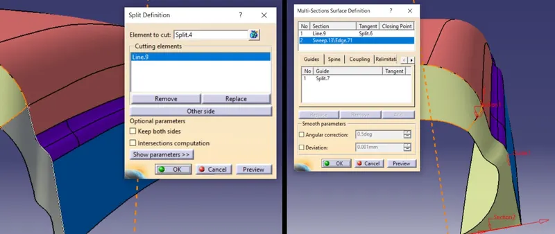 Fig45: Splitting and creating the left edge surfaces
- For the right edges, to provide a smooth transition at the joining portion of the bottom and side surfaces, the bottom surface was extrapolated and trimmed using an inclined line
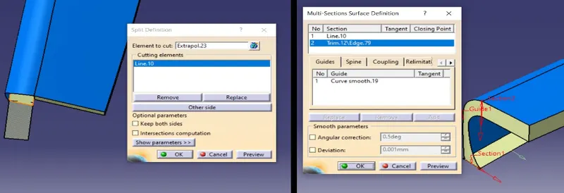 Fig46: Right edge surface creation
- The C-surface creation was now completed
8. Joining the Class-A and C-surfaces together
- The first step in the final procedure for completing the model was to join the Class-A and C-surfaces together
- This was achieved using the Join surfaces tool with a merging distance of 0.003mm to nullify gaps along the joining edges
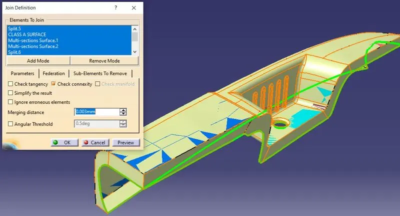 Fig47: Joining tool used for A and C surfaces
Fig48: Class-A and C surfaces (Joined)
9. Creating the final surface model
- To complete the final surface model of the component, the previously joined Class-A and C-surfaces were trimmed with the B-surface using the Trim surface tool
- Using the boundary tool, checks were done for any irregularities (gaps) in the final surface model and it was found that the model was intact
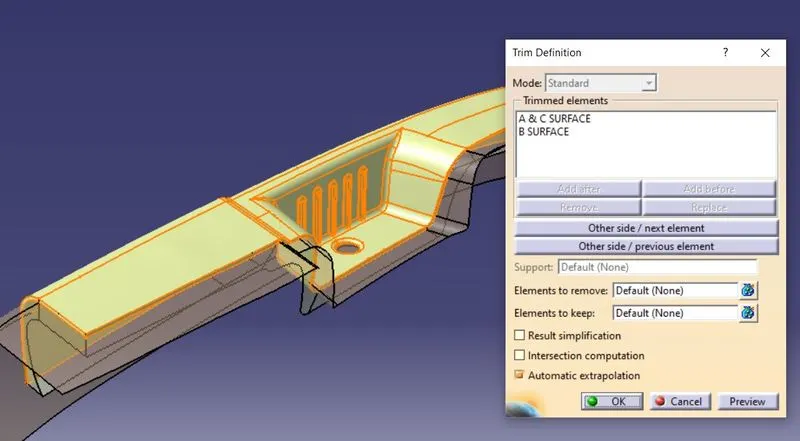 Fig49: Final trim to create the surface model
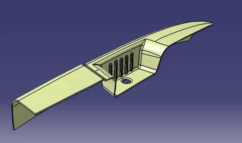 Fig50: Surface model of the door arm rest
10. Creating the solid model
- The final step included the conversion of the surface model into a solid model
- Using the Close surface tool in the part workbench, the surface model was successfully converted into a solid model
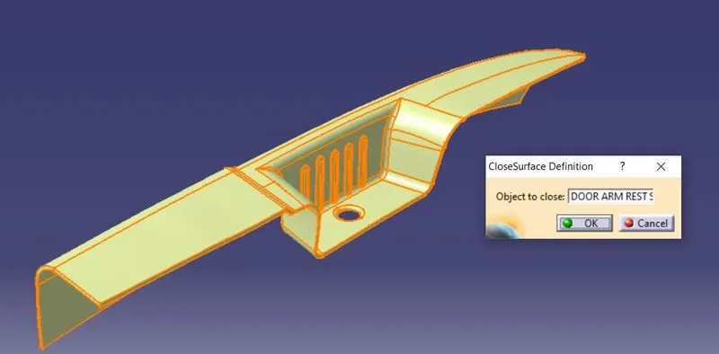 Fig51: Closed surface tool
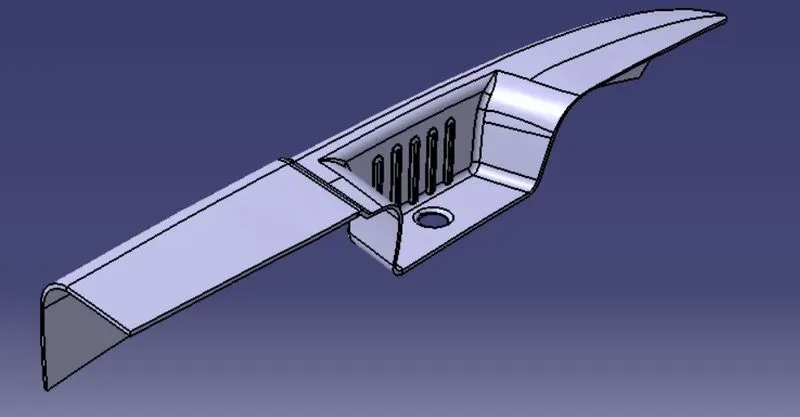 Fig52: Final solid model of the door arm rest
11. Performing draft analysis of the solid model
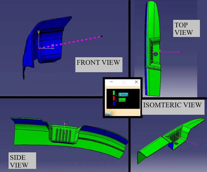
- To check the final model for manufacturability, draft analysis along the main tooling axis and the side core axis were done
- It was observed that the model passed all the checks necessary to clear the tooling
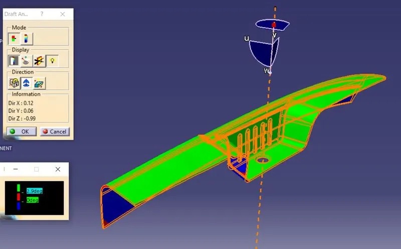 Fig53: Draft analysis of the solid model along main tooling axis
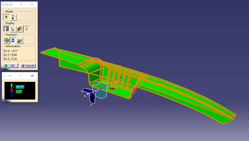 Fig54: Draft analysis of the solid model along side core axis
12. Publishing the necessary components
- Publishing geometrical elements makes them available for different users and is important from an assembly context
- In this project, the Class-A, B, C surfaces, the final surface component and both the tooling axis were published
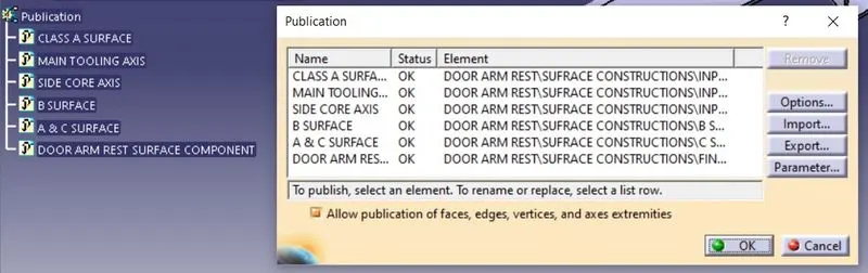 Fig55: Publication
DRAFT ANALYSIS: RESULTS
Class-A surface:
- Main tooling axis
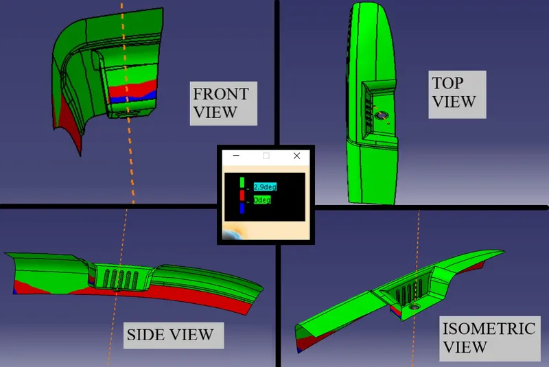
- Side Core axis
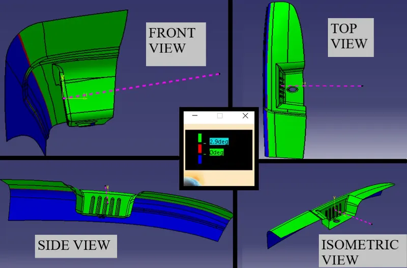
Solid Model:
- Main tooling axis
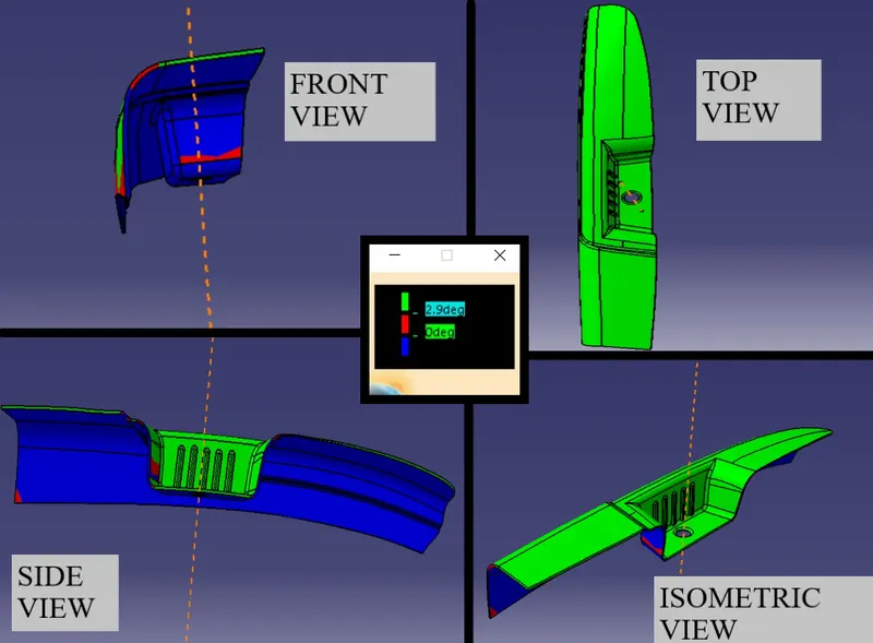
- Side core axis
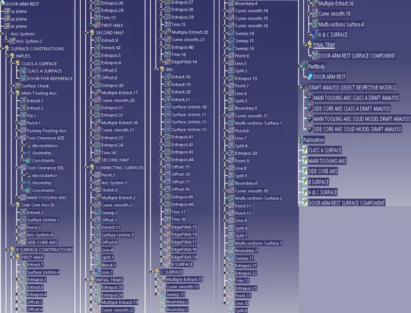
FEATURE TREE OF THE MODEL
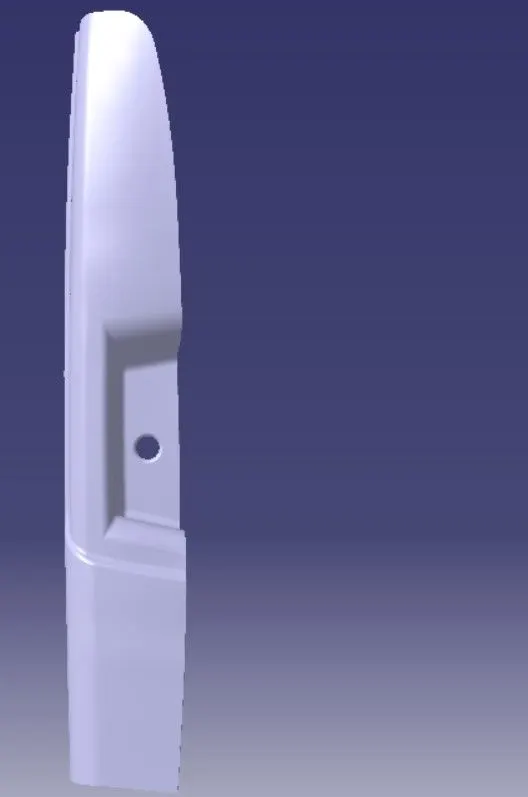
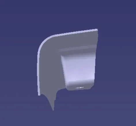
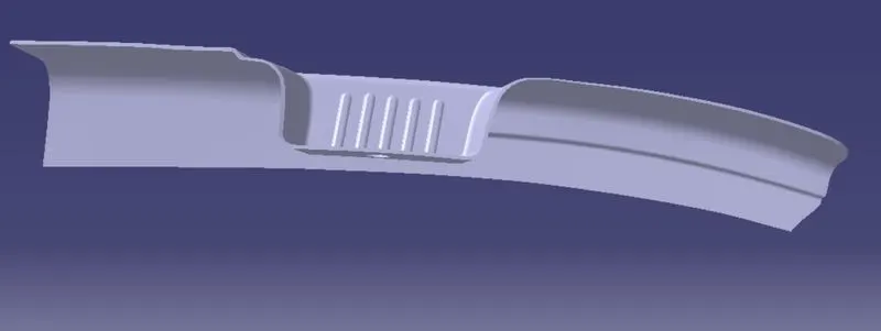
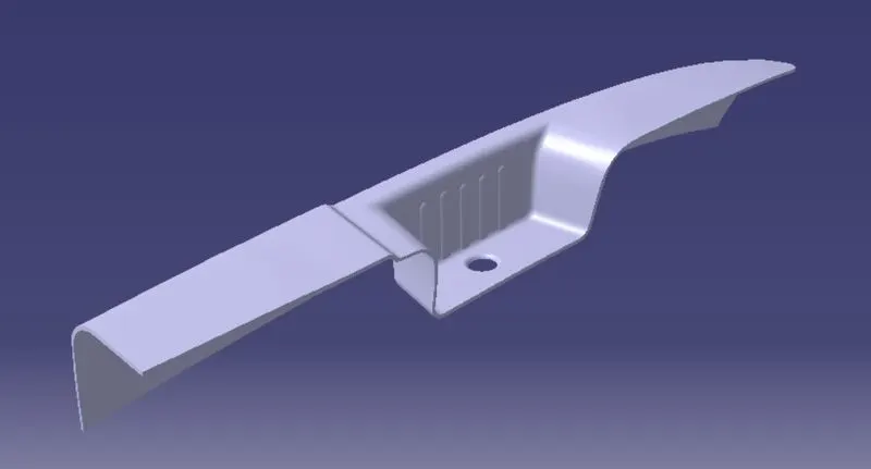
STANDARD VIEWS OF THE SOLID MODEL
TOP VIEW
FRONT VIEW
SIDE VIEW
ISOMETRIC VIEW
CONCLUSION
This project imparted a great deal of knowledge regarding the creation of tooling axis, concept of side core and performing proper draft analysis on a component which are essential steps to ensure a design is fit for manufacture. It also provided valuable insights on the design of a plastic component using Class A, B and C surfaces using CATIA.
REFERENCES