Creation of Column Schedule and Drawing Template using AutoCad
1. COLUMN SCHEDULE:

Aim: To create a Column Schedule as Shown in the figure above with the help of lines using AutoCAD.
Introduction:
The Column Schedule is created in AutoCAD using line and text tool.
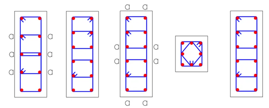
- The clear cover for all the columns is provided with 1.6" (approx. 40 mm). As per IS 256, the minimum cover to the column should not be less than 40 mm.
- All columns are provided with 8 mm dia. stirrups with 3" c/c spacing near the ends and 8" c\c in center.
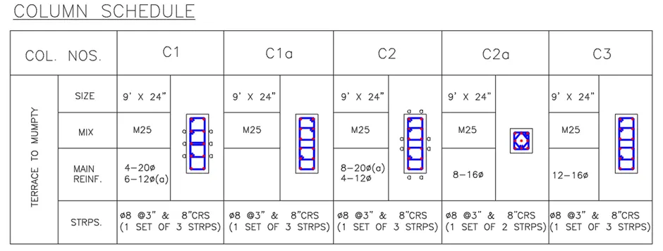
- Column C1 is provided with 4 bars of 20 mm dia. at four corners and 6 bars of 12 mm dia. in between them. The 12 mm dia. bars are marked as 'a'.
- Column C1a and Column C3 are provided with 12 bars of 16 mm dia. bars.
- Column C2 is provided with 8 bars of 20 mm dia. and 4 bars of 12 mm dia. The 20 mm dia. bars are marked with 'a'.
- Column C2a is provided with 8 bars of 16 mm dia.
Procedure:
- Type unit or UN in the command line and press enter
- Set type of unit as engineering and precision as 0’0”
- In insertion scale set unit as inches.
Note:
Diameter of bars is provided in mm need to convert to inch
The following table contains converted diameter of bars. (1” = 25.4 mm)
|
Dia. of bar in mm |
Dia. of bar in inch |
|
20 |
0.7874 |
|
16 |
0.63 |
|
12 |
0.4724 |
|
8 |
0.315 |
- Draw rectangle for the given column dimension.
- Then invoke the offset tool and provide an inside offset of 1.6” for rectangle.
- Draw circles inside the rectangle for the respective diameters according to their positions
- And use divide command to provide equal spacing.
- After drawing the circles on one side, use mirror command to replicate the circles to other side and hatch the circles with solid fill
- Draw the stirrups using rectangle tool in the column where they are required according to position.
- Bend the corner of stirrups to the 45 degrees.
Follow the same steps to draw all column details.
Draw a table and adjust the rows and columns as per requirements
Use Multiline text to write the details of columns in respective cells
RESULT
2. WINDOW SCHEDULE:

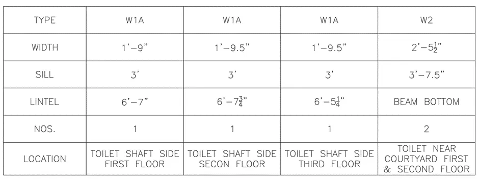
Aim: To create a Window Schedule with the help of Table and Text Command as shown in the Figure above in the AutoCAD.
Introduction:
The Desired Window Schedule is created in AutoCAD using the Table and text tool. The procedure of drawing is explained in detail with diagrams of each step and the final result is given.
Procedure:
- Type unit or UN in the command line and press enter
- Set type of unit as engineering and precision as 0’0”
- In insertion scale set unit as inches.
Insert a Table from Annotate tab and adjust the rows and columns as per requirements
Use Multiline text to write the details in respective cells
RESULT
3. DRAWING TEMPLETE:


Aim: To create a Drawing Template with the help of Table and Text Command as shown in the Figure above in the AutoCAD.
Introduction:
The Desired Drawing Template is created in AutoCAD using the Table and text tool. The procedure of drawing is explained in detail with diagrams of each step and the final result is given.
Procedure:
- Type unit or UN in the command line and press enter
- Set type of unit as engineering and precision as 0’0”
- In insertion scale set unit as inches.
Draw a table using line tool and adjust the rows and columns as per requirements
Use Multiline text to write the details of columns in respective cells
RESULT

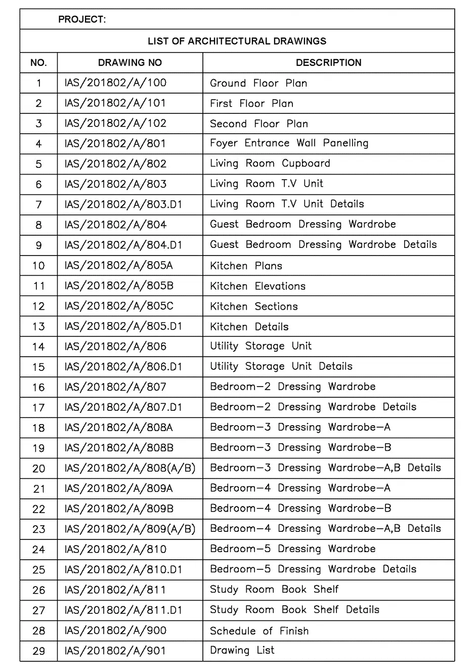
4. List of Drawing Schedule:

Aim: To create the list of Drawing Schedule with the help of table and text tools as shown in the Figure above in AutoCAD.
Introduction:
The list of Drawing Schedule is created in AutoCAD using the Table and text tool. The procedure of drawing is explained in detail with diagrams of each step and the final result is given.
Procedure:
- Type unit or UN in the command line and press enter
- Set type of unit as engineering and precision as 0’0”
- In insertion scale set unit as inches.
Draw a table using line tool and adjust the rows and columns as per requirements
Use Multiline text to write the details of columns in respective cells
RESULT
5. Beam Detail:

Aim: To create the Beam Detail drawing as shown in the Figure above in AutoCAD.
Introduction:
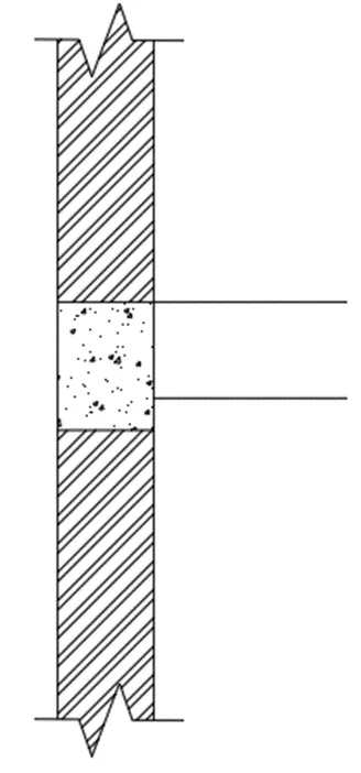
The Beam Detail drawing is created in AutoCAD using the line, hatch, multileader and text tool. The procedure of drawing is explained in detail with diagrams of each step and the final result is given.
Procedure:
Step 1
Type unit or UN in the command line and press enter
Set type of unit as engineering and precision as 0’0”
In insertion scale set unit as inches.
Step 2
Type line or L in the command line and press enter
Using line command draw the wall and beam
Type hatch or HA in the command box and press enter
Hatch the wall internal portion
Step 3
Type DIM in the command box and press enter
Add required dimensions to drawing
Type quick leader or QL in the command box and press enter
Select the object draw arrow and name the object
Type TEXT in the command box and press enter to name
RESULT