Drafting of various geometries using Chamfer, Fillet tool in AutoCad
INTRODUCTION
Fillet: Fillets generally refer to rounding the interior or exterior corner of a part. It is an edge and rounded corner of a piece and maybe inside or outside of the part. When we define fillet, the Exterior fillet is convex, and the inlet fillet is concave. The primary purpose of their uses is for the lower stress concentration factor and uniform distribution of stress.
According to fillet definition, a fillet generally is rounded edges or corners, and rounding of an interior corner is called fillet radii. Fillet radii can employ on casting to improve the quality and also use for the increment of load-bearing strength. Therefore, fillet radius is a standard allowance in a casting design.
Chamfer: The chamfer is a sloped or angled corner or edge, mainly used to keep the edge safe from damage and give a more uniform look to the rough edge. Chamfer edges are sharp and straight, rather than smooth edges, and are used for low-stress concentration as they can deform the material. So, it is not recommended for high-stress concentration edges. For any design, you must have knowledge of chamfer edge vs. bevel edge and the function of chamfer in AutoCAD to make a comparison and sound decision. A bevel is a sloped edge on top and a chamfer has a beveled edge on the bottom that can connect with two surfaces.
A chamfer is an angled or sloped edge or type of bevel. In mechanical engineering, we can classify chamfer into two subgroups:
- Chamfer with 45-degree use for removing bur in the drilling operation. The chamfers allow a bolt to sit below the flush fir surface rather than sticking out.
- Chamfer with 60 degrees has sharp corners and is not much effective in reducing stress concentration. They use as a lead-in for a bolt and screw. The chamfering is essential after the parts finishing process to make a furrow, groove, or bevel.
Fillet & chamfer in AutoCAD:
The fillet and chamfer command in Auto Cad definition modify a pair of objects, whereas chamfer can create a beveled corner, and a fillet can create a curved corner in the middle of two lines.
1.
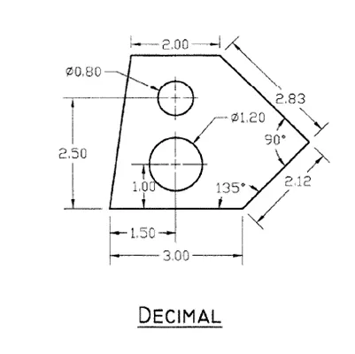
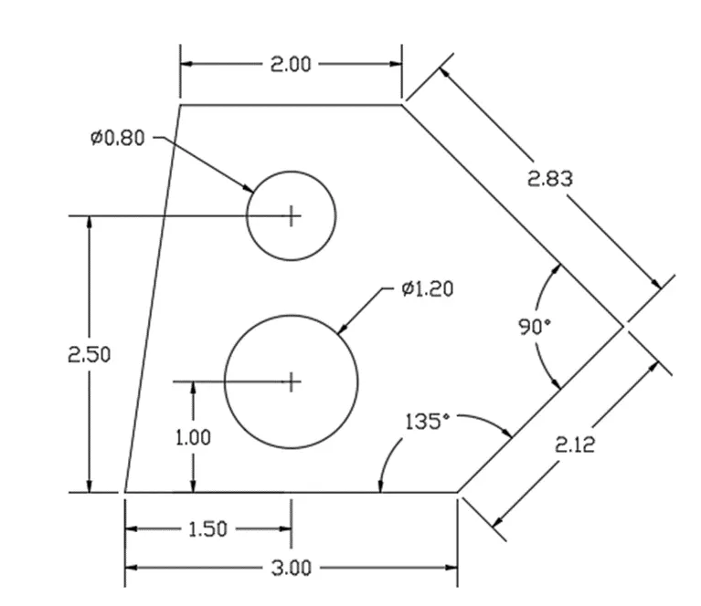
Aim: To create given geometry using AutoCAD tools in Decimal units
Procedure:
Step 1
Type unit or UN in the command line and press enter
Set type of unit as decimal and precision as 0.00
|
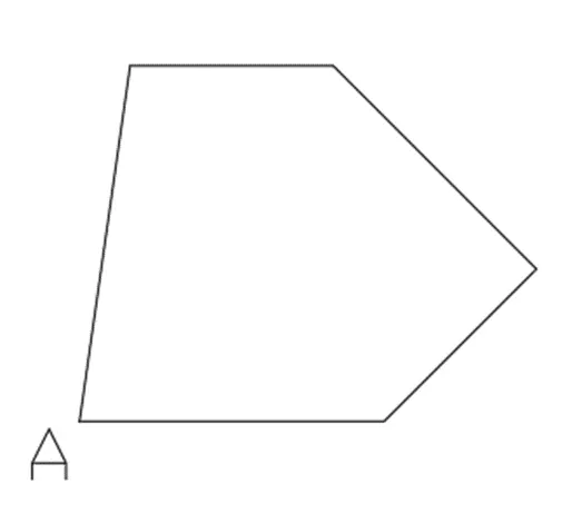
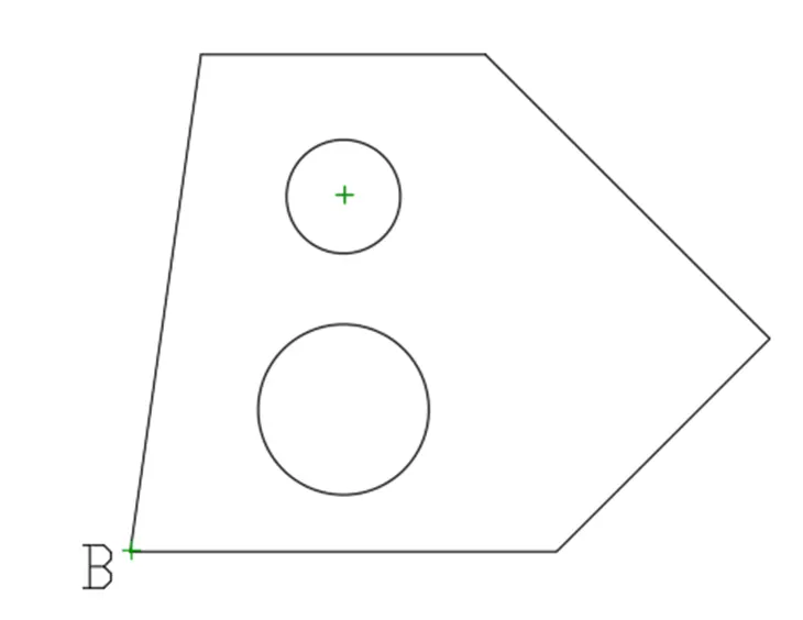
Step 2 Type PL in the command line then press enter to invoke polyline tool Specify the first point A on the screen Specify next point @3,0 Specify next point @2.12<45 Specify next point @2.83<135 Specify next point @-2, 0 Type C and press enter to close polyline tool |
 |
|
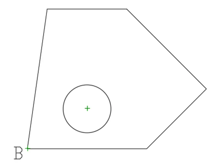
Step 3 Type C in the command line then press enter to invoke circle tool From the temporary reference point B select circle center @1.5,1 Type D and click Enter to specify circle diameter Specify diameter 1.2 |
 |
|
Step 4 Type C in the command line then press enter to invoke circle tool From the temporary reference point B select circle center @1.5,2.5 Type D and click Enter to specify circle diameter Specify diameter 0.8 Step 5 Use dimension tool to measure the distance and angle |
 |
RESULT
The figure given is drawn using Polyline, circle, dimension tool.
2.
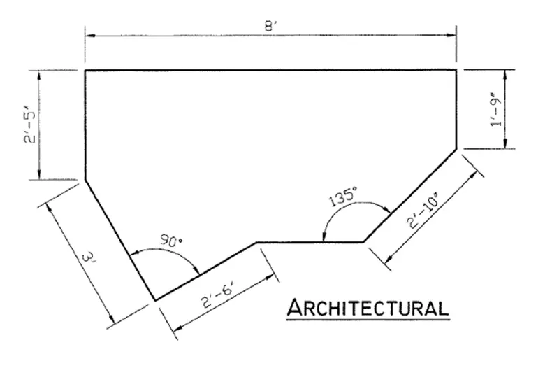
Aim: To create given geometry using AutoCAD tools in Architectural units
Procedure:
Step 1
Type unit or UN in the command line and press enter
Set type of unit as architecture and precision as 0’-0”
|
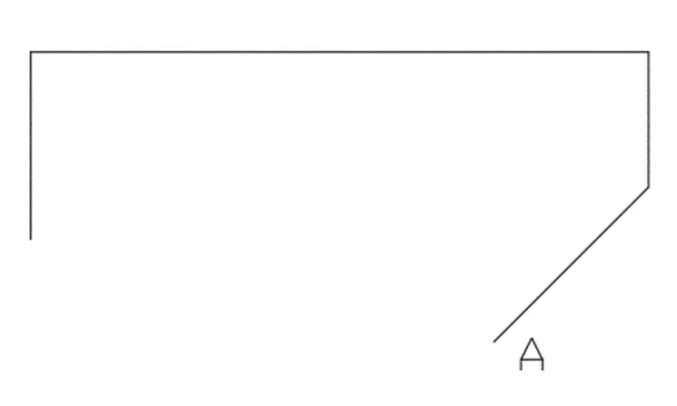
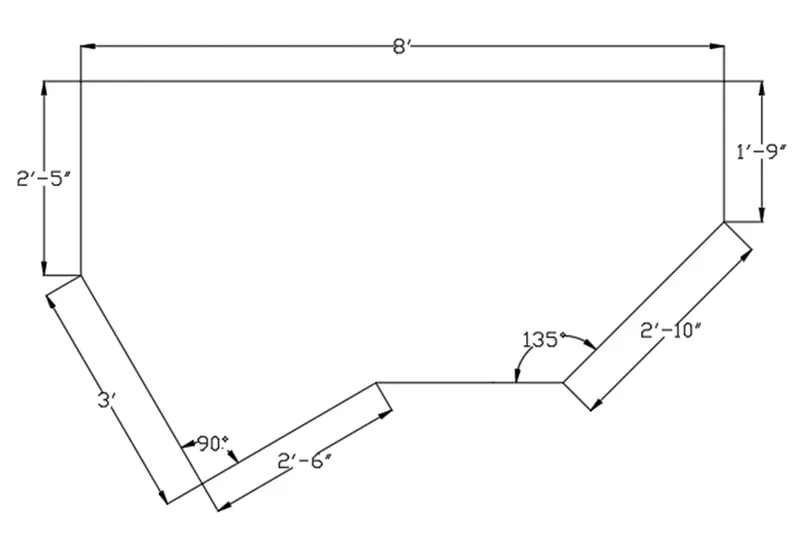
Step 2 Type PL in the command line then press enter to invoke polyline tool Specify the first point A on the screen Specify next point @2’ 10” <45 Specify next point @0, 1’9” Specify next point @-8, 0 Specify next point @0, -2’5” Press Esc key to exit from polyline tool |
 |
|
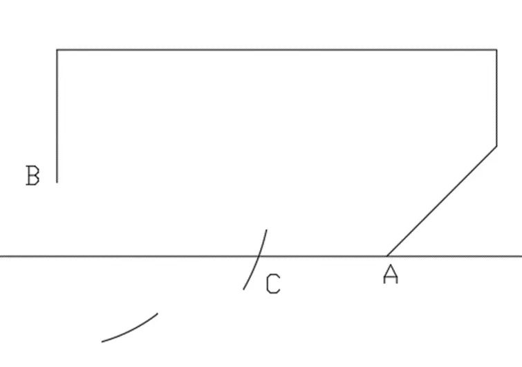
Step 3 Type XL in the command line to invoke continuous line Type H and press Enter to select horizontal continuous line Create a continuous line at point A Press Esc & exit from command Select center, start end arc from the Home tab Draw palette Specify the center point at B Specify arc radius 3.903’ Select the start and end point of arc which intersect the continuous line
Step 4 Select center, start end arc from the Home tab Draw palette Specify the center point at B to draw another arc Specify arc radius 3’ Select the start and end point of arc |
 |
|
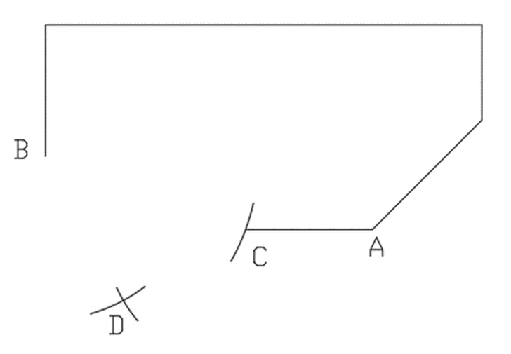
Step 5 Select center, start end arc from the Home tab Draw palette Specify the center point at C to draw arc Specify arc radius 2’6” Select the start and end point of arc to cut previous arc at point D |
 |
|
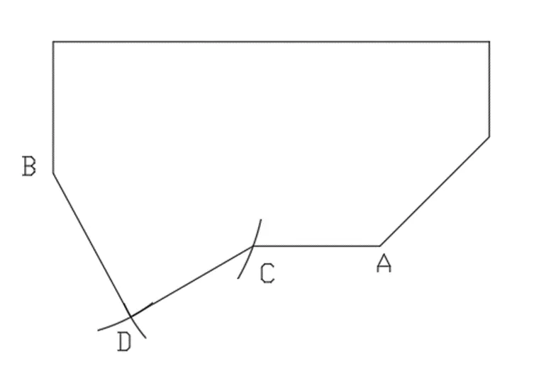
Step 6 Type PL in the command line then press enter to invoke polyline tool Join the points BDC Step 7 Erase the unwanted arcs by selecting them and trim the line to get the geometry Use dimension tool to measure the distance and angle |
 |
RESULT
The figure given is drawn using Polyline, arc, continuous line and dimension tool.
3.
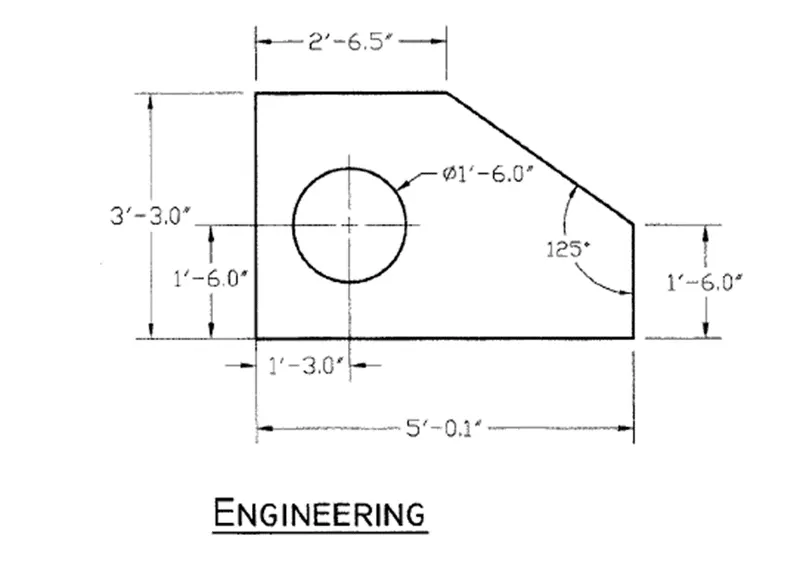
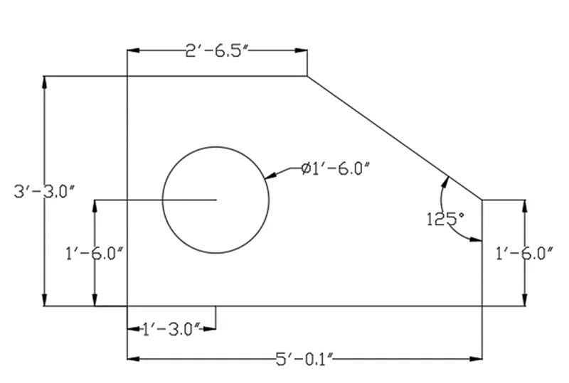
Aim: To create given geometry using AutoCAD tools in Engineering units
Procedure:
Step 1
Type unit or UN in the command line and press enter
Set type of unit as Engineering and precision as 0’ 0.0”
|
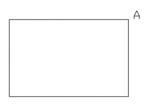
Step 2 Type REC in the command line then press enter to invoke rectangle tool Specify the first point on the screen Type D and Press Enter to specify dimension of rectangle Specify rectangle length 5’ 0.1” then Enter Specify rectangle width 3’ 3” |
 |
|
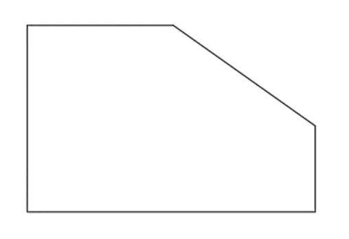
Step 3 Type CHA in the command line then press enter to invoke chamfer tool Specify the first length 1’ 9” Specify the second length 2’ 5.6” Select the first line which is vertical line intersection at point A Select the second line which is horizontal line intersection at point A |
 |
|
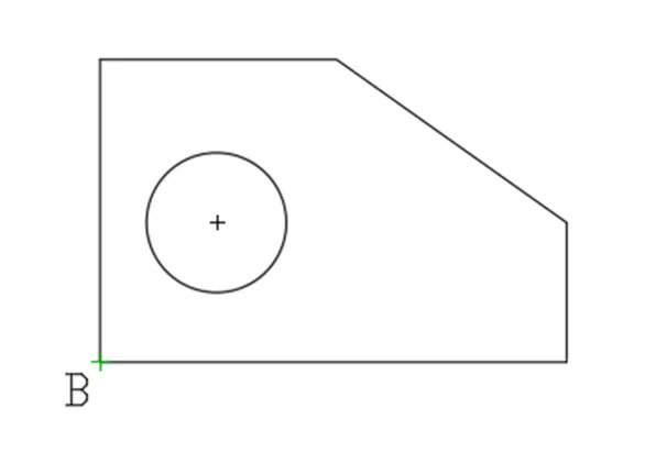
Step 4 Type C in the command line then press enter to invoke circle tool From the temporary reference point B select circle center @1’ 3”, 1’ 6” Type D and click Enter to specify circle diameter Specify diameter 1’ 6” Step 5 Use dimension tool to measure the distance and angle |
 |
RESULT
The figure given is drawn using Rectangle, chamfer, circle, dimension tool.
4.
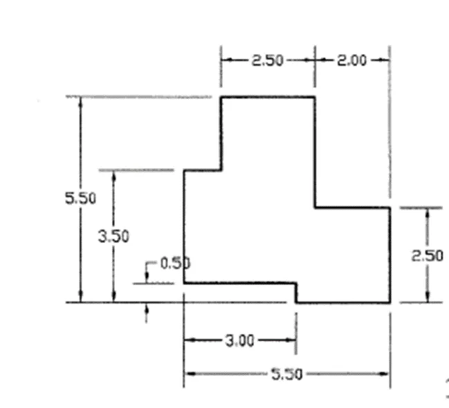
Aim: To create given geometry using AutoCAD tools in Decimal units
Procedure:
Step 1
Type unit or UN in the command line and press enter
Set type of unit as decimal and precision as 0.00
Step 2
Click F8 to turn on ortho mode or turn it on from status bar
Type PL in the command line then press enter to invoke polyline tool
Specify the first point on the screen
Specify next point by position of the cursor towards right side of the screen and enter distance 3
Specify next point by position of the cursor to down side of the screen and enter distance 0.5
Specify next point by position of the cursor towards right side of the screen and enter distance 2.5
Specify next point by position of the cursor towards up side of the screen and enter distance 2.5
Specify next point by position of the cursor towards left side of the screen and enter distance 2
Specify next point by position of the cursor towards up side of the screen and enter distance 3
Specify next point by position of the cursor towards left side of the screen and enter distance 2.5
Specify next point by position of the cursor towards down side of the screen and enter distance 2
Specify next point by position of the cursor towards left side of the screen and enter distance 1
Type C and press enter to close polyline tool
Step 3
Use dimension tool to measure the distance and angle
RESULT
The figure given is drawn using line and dimension tool.
5.
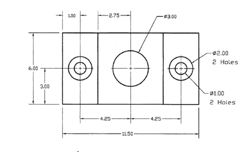
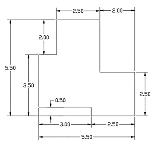
Aim: To create given geometry using AutoCAD tools in Decimal units
Procedure:
Step 1
Type unit or UN in the command line and press enter
Set type of unit as decimal and precision as 0.00
|
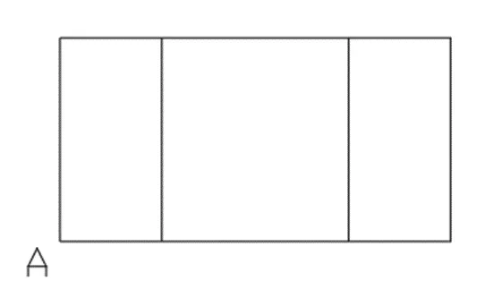
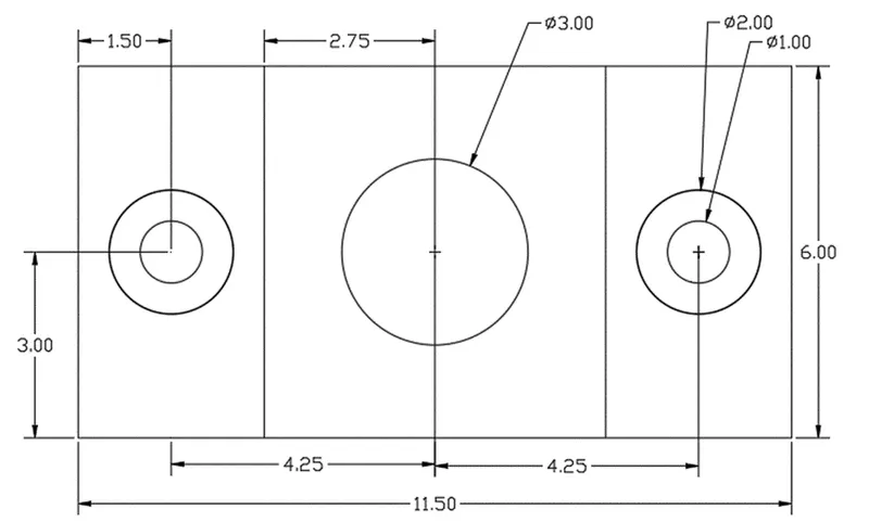
Step 2 Click F8 to turn on ortho mode or turn it on from status bar Type L in the command line then press enter to invoke line tool Specify the first point on the screen Specify next point @11.5, 0 Specify next point @0, 6 Specify next point @-11.5, 0 Type C close line tool Step 3 Type offset or O in the command box and press enter Type T to select Through Specify offset distance 3 from A Then enter offset distance 5.25from new line Press Esc to exit from command |
 |
|
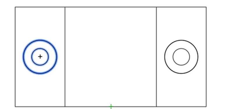
Step 4 Type C in the command line then press enter to invoke circle tool From the temporary reference point A, select circle center @1.5, 3 Type D and click Enter to specify circle diameter Specify diameter 2 Create another circle from the same center point Specify diameter 1 Step 5 Type MI in the command bar to invoke mirror tool Select the two circle and press Enter Create a vertical mirror line from the center of the rectangular geometry Type N and press Enter |
 |
|
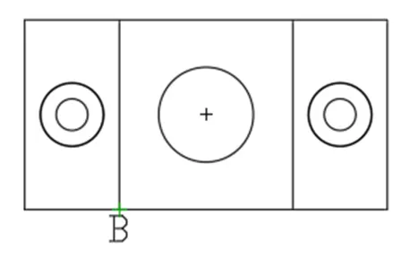
Step 6 Type C in the command line then press enter to invoke circle tool From the temporary reference point B, select circle center @2.75, 3 Type D and click Enter to specify circle diameter Specify diameter 3 Step 7 Use dimension tool to measure the distance and angle |
 |
RESULT
The figure given is drawn using line, circle, dimension tool.
6.
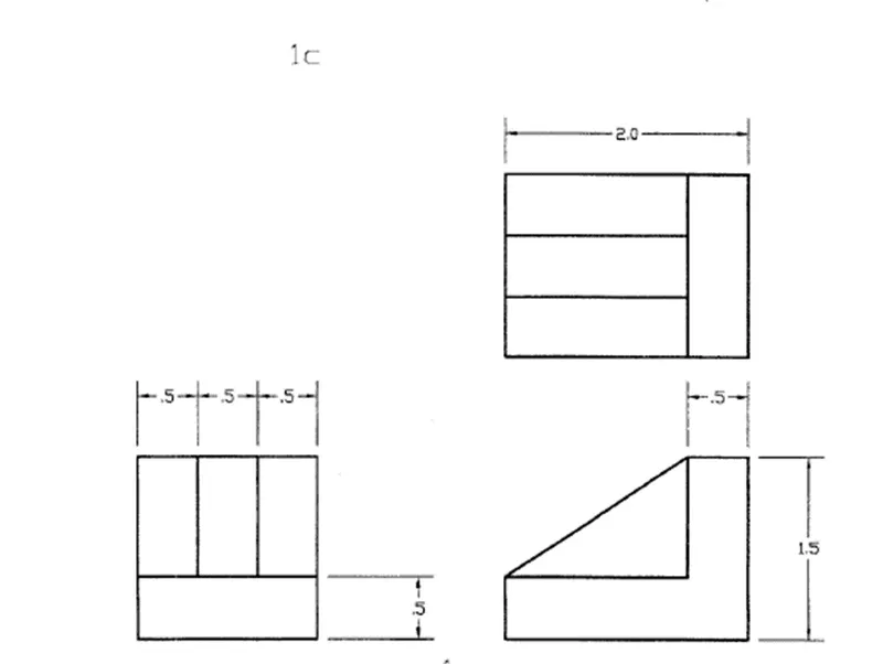
Aim: To create given geometry using AutoCAD tools in Decimal units
Procedure:
Step 1
Type unit or UN in the command line and press enter
Set type of unit as decimal and precision as 0.0
|
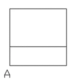
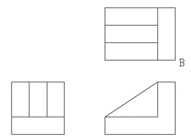
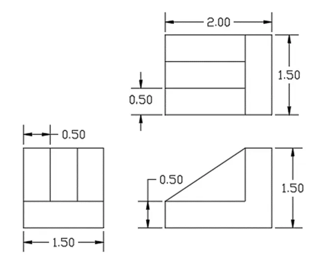
Step 2 Type REC in the command line then press enter to invoke rectangle tool Specify the first point A on the screen Specify the next point @1.5, 1.5 Type L in the command line then press enter to invoke line tool From the reference point A draw a line @0, 0.5 |
 |
|
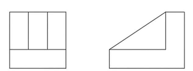
Step 3 Type offset or O in the command box and press enter Specify offset distance 0.5 Select object to offset Exit the command Step 4 Type L in the command line then press enter to invoke line tool Specify first point on the screen Specify next point @2, 0 Specify next point @0, 1.5 Specify next point @-0.5, 0 Specify next point @0, -1 Specify next point @-1.5, 0 Type C to close line tool Type L in the command line then press enter to invoke line tool Join the points to create a sloped line |
 |
|
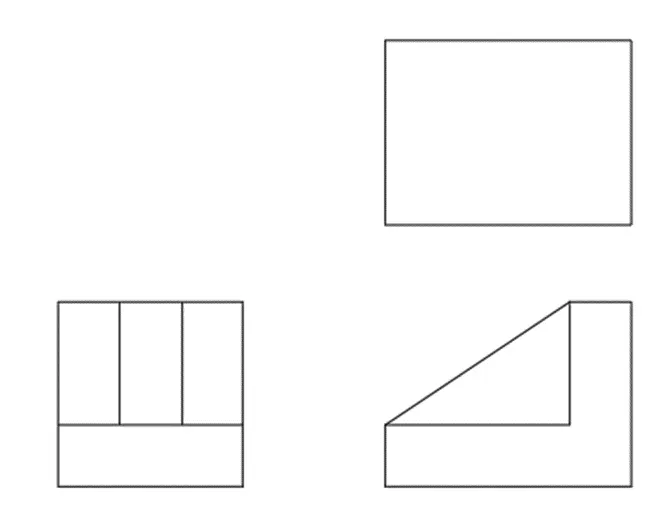
Step 4 Type REC in the command line then press enter to invoke rectangle tool Specify first point on the screen Specify next point @2, 1.5 |
 |
|
Step 5 Type L in the command line then press enter to invoke line tool From the reference point B draw a line @0, 0.5 Step 6 Type offset or O in the command box and press enter Specify offset distance 0.5 Select object to offset Exit the command Step 7 Use dimension tool to measure the distance and angle |
 |
RESULT
The figure given is drawn using line, rectangle, offset and dimension tool.
7.
Aim: To create given geometry using AutoCAD tools in Decimal units
Procedure:
Step 1
Type unit or UN in the command line and press enter
Set type of unit as decimal and precision as 0
|
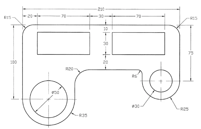
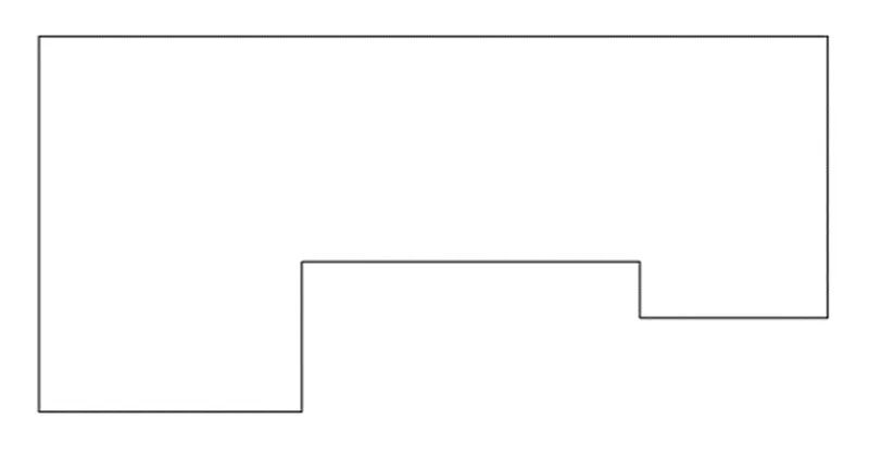
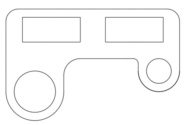
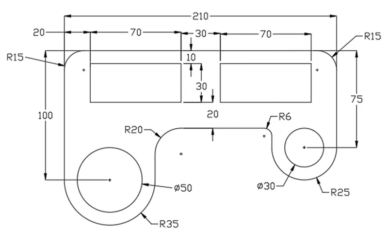
Step 2 Type L in the command line then press enter to invoke line tool Specify first point the screen Specify next point by position of the cursor towards up side of the screen and enter distance 100 Specify next point by position of the cursor towards right side of the screen and enter distance 210 Specify next point by position of the cursor towards down side of the screen and enter distance 75 Specify next point by position of the cursor towards right side of the screen and enter distance 50 Specify next point by position of the cursor towards up side of the screen and enter distance 15 Specify next point by position of the cursor towards left side of the screen and enter distance 90 Specify next point by position of the cursor towards down side of the screen and enter distance 40 Type C and press enter to close line tool |
 |
|
Step 3 Type C in the command line then press enter to invoke circle tool Select the midpoint of line as circle center in the left side Type D and click Enter to specify circle diameter Specify diameter 50 Create another circle from the same center point Specify radius 35 |
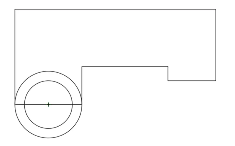 |
|
Step 4 Type C in the command line then press enter to invoke circle tool Select the midpoint of line as circle center in the right side Type D and click Enter to specify circle diameter Specify diameter 30 Create another circle from the same center point Specify radius 25 |
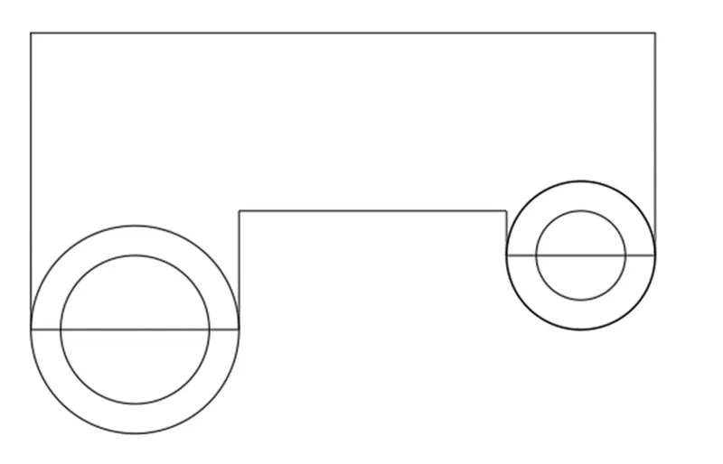 |
|
Step 5 Type REC in the command line then press enter to invoke rectangle tool Specify first point from the reference point A @20, -10 Specify next point @70, -30 |
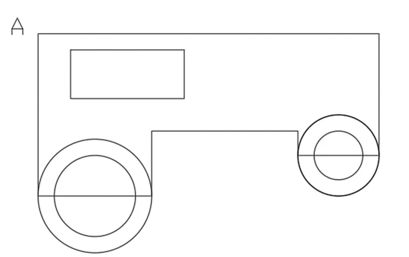 |
|
Step 6 Type CO in the command line then press enter to invoke copy tool Copy rectangle from base point B Specify the coordinate to place the copy @100, 0 |
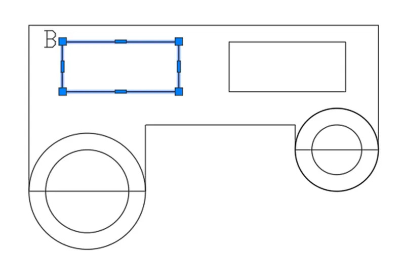 |
|
Step 7 Type F in the command line then press enter to invoke fillet tool Fillet the corners with the respective fillet radius Type TR in the command line then press enter to invoke trim tool Trim the extra line Step 8 Use dimension tool to measure the distance and angle |
 |
RESULT
The figure given is drawn using line, rectangle, copy, circle, fillet, trim and dimension tool.
8.
Aim: To create given geometry using AutoCAD tools in Decimal units
Procedure:
Step 1
Type unit or UN in the command line and press enter
Set type of unit as decimal and precision as 0.000
|
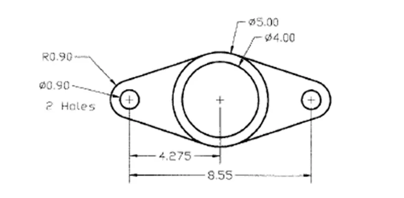
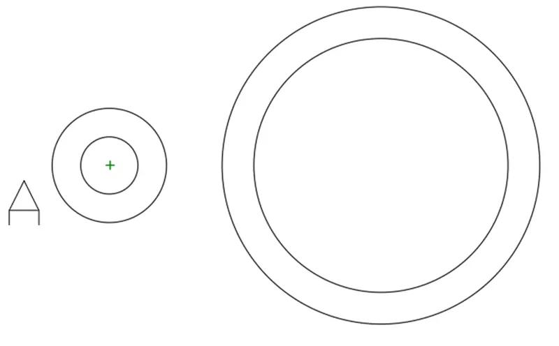
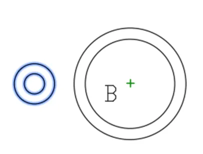
Step 2 Type C in the command line then press enter to invoke circle tool Select the center of the circle on the screen Type D and click Enter to specify circle diameter Specify diameter 0.9 Create another circle from the same center point Specify radius 0.9 |
 |
|
Step 3 Type C in the command line then press enter to invoke circle tool Select center point from reference point A @8.55, 0 Type D and click Enter to specify circle diameter Specify diameter 5 Create another circle from the same center point Specify diameter 4 |
 |
|
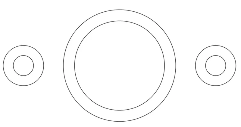
Step 4 Type MI in the command bar to invoke mirror tool Select the two circle and press Enter Create a vertical mirror line from the refence point B Type N and press Enter Step 5 Type L in the command line then press enter to invoke line tool Type tan to create tangent to the circle |
 |
|
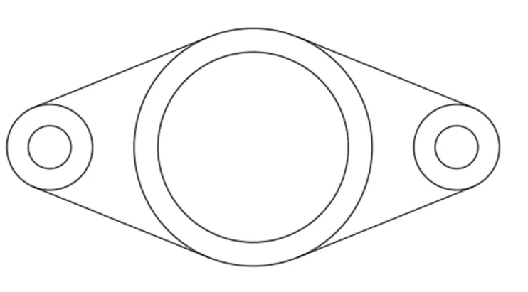
Step 6 Type TR in the command line then press enter to invoke trim tool Trim the extra line Step 7 Use dimension tool to measure the distance and angle |
 |
RESULT
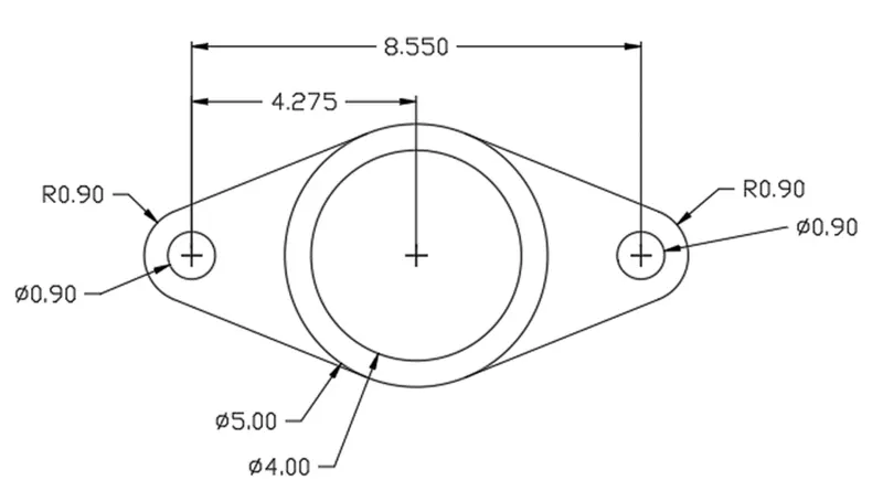
The figure given is drawn using line, mirror, circle, trim and dimension tool.
9.
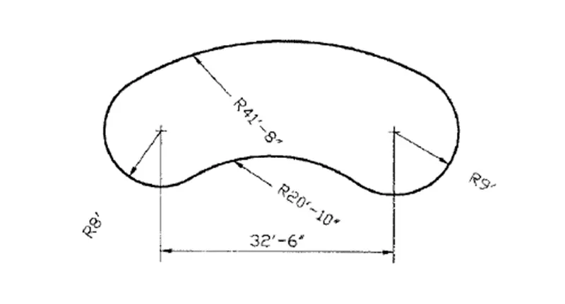
Aim: To create given geometry using AutoCAD tools in Engineering units
Procedure:
Step 1
Type unit or UN in the command line and press enter
Set type of unit as Engineering and precision as 0’ 0”
|
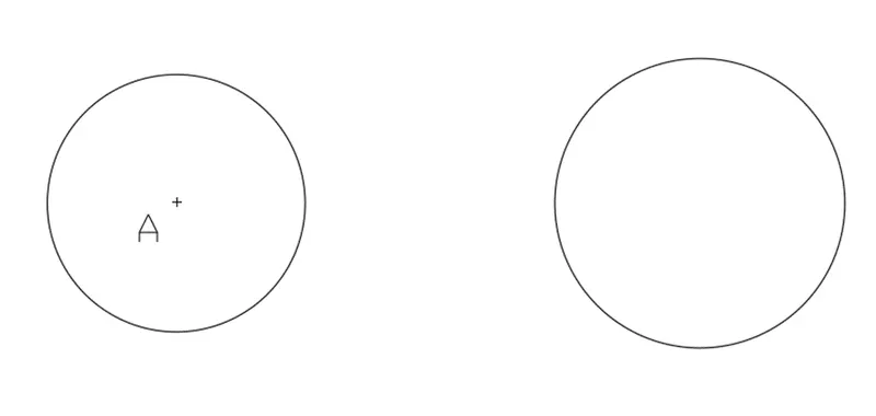
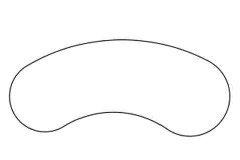
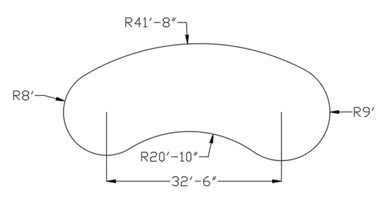
Step 2 Type C in the command line then press enter to invoke circle tool Select the center of the circle on the screen Specify radius 8’ Create another circle from reference point A @ 32’ 6” Specify radius 9’ |
 |
|
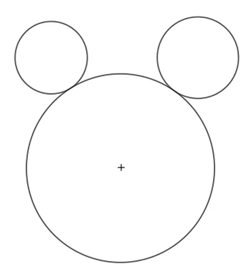
Step 3 Type C in the command line then press enter to invoke circle tool Type TTR Specify point on object for first tangent of circle - select the bottom first circle Specify point on object for second tangent of circle - select the bottom second circle Specify radius 41’ 8” and press enter |
 |
|
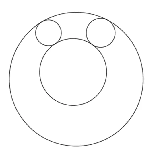
Step 4 Type C in the command line then press enter to invoke circle tool Type TTR Specify point on object for first tangent of circle - select the top first circle Specify point on object for second tangent of circle - select the top second circle Specify radius 20’ 10” and press enter |
 |
|
Step 5 Type trim or TR and press enter Select the object which needs to be trimmed Step 6 Use dimension tool to measure the distance and angle |
 |
RESULT
The figure given is drawn using circle, trim and dimension tool.
10.
Aim: To create given geometry using AutoCAD tools in Decimal units
Procedure:
Step 1
Type unit or UN in the command line and press enter
Set type of unit as decimal and precision as 0
|
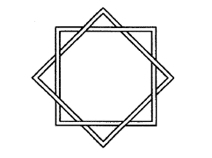
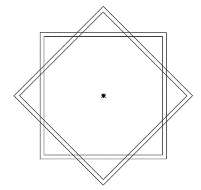
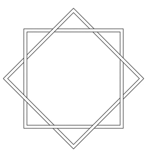
Step 2 Type REC in the command line then press enter to invoke rectangle tool Specify the first point on the screen Specify next point @5,5 Type offset or O in the command box and press enter Specify offset distance 2 Select object to offset Exit the command |
 |
|
Step 3 Type RO in the command box and press enter Specify base point - select the midpoint of the polygon Specify rotation angle 45 Step 4 Type TR and press enter Select the object which needs to be trimmed |
 |
RESULT
The figure given is drawn using rectangle and trim tool.
11.
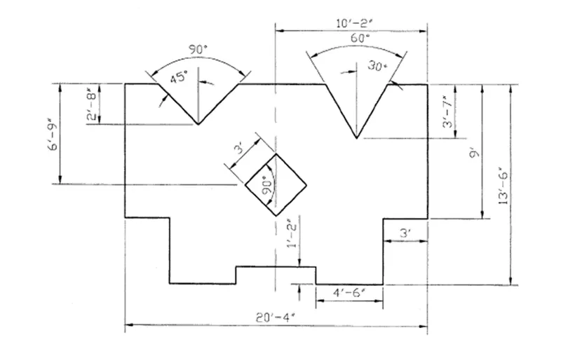
Aim: To create given geometry using AutoCAD tools in Engineering units
Procedure:
Step 1
Type unit or UN in the command line and press enter
Set type of unit as Engineering and precision as 0’ 0”
|
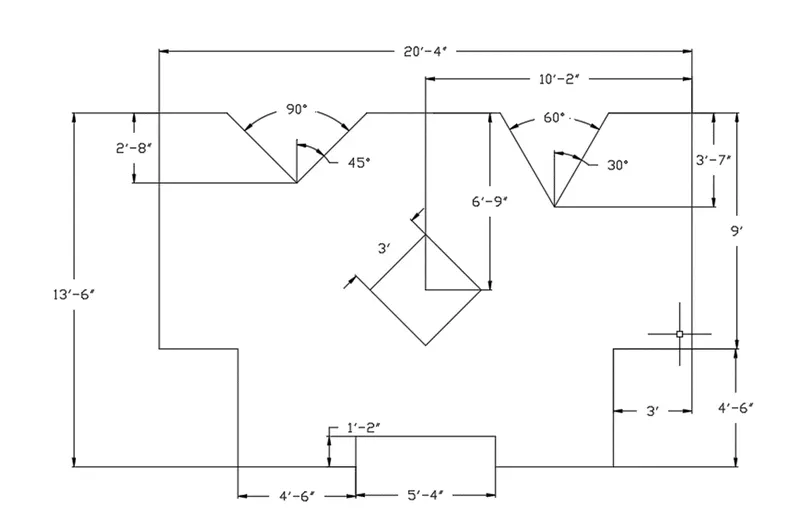
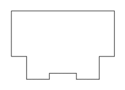
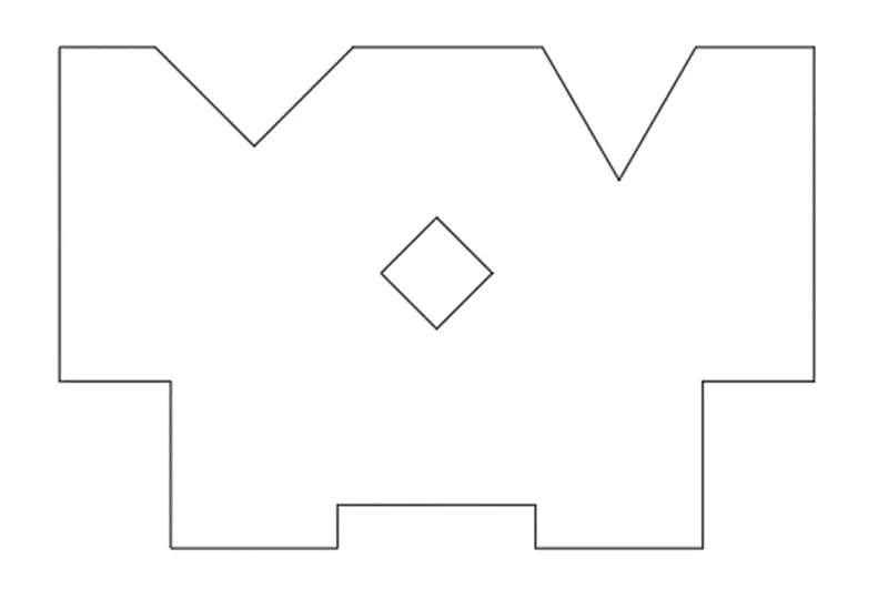
Step 2 Type L in the command line then press enter to invoke line tool Specify the first point on the screen Specify next point by position of the cursor towards right side of the screen and enter distance 3’ Specify next point by position of the cursor towards down side of the screen and enter distance 4’ 6” Specify next point by position of the cursor towards right side of the screen and enter distance 4’ 6” Specify next point by position of the cursor towards up side of the screen and enter distance 1’ 2” Specify next point by position of the cursor towards right side of the screen and enter distance 5’ 4” Specify next point by position of the cursor towards down side of the screen and enter distance 1’ 2” Specify next point by position of the cursor towards right side of the screen and enter distance 4’ 6” Specify next point by position of the cursor towards up side of the screen and enter distance 4’ 6” Specify next point by position of the cursor towards right side of the screen and enter distance 3’ Specify next point by position of the cursor towards up side of the screen and enter distance 9’ Specify next point by position of the cursor towards left side of the screen and enter distance 20’ 4” Type C and press enter to close line tool |
 |
|
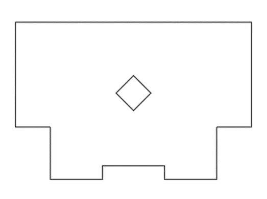
Step 3 Type POL in the command line to invoke polygon tool Enter number of sides - 4 and press enter Specify center of polygon select the center point and press enter Press C to select circumscribed and press enter Specify radius of circle 3’<45 and press enter |
 |
|
Step 4 Type L and press enter By using line command complete the drawing Type trim or TR in the command box and press enter Select the object which needs to be trimmed Step 5 Use dimension tool to measure the distance and angle |
 |
RESULT
The figure given is drawn using line, polygon, trim and dimension tool.