Creating a Floor plan, Footing detail and Isometric view using AutoCad
AIM:
To Creating a Floor plan, Footing detail and Isometric view using AutoCAD.
INTRODUCTION:
Floor plan:
Floor plan is two-dimensional technical drawing to scale showing a view from above, of the relationships between rooms, spaces, traffic patterns, and other physical features at one level of a structure. Architects use floor plans as tool to design buildings. Later, they are described buildings to those involved in the construction process.
Footing:
Footing is a part of foundation which is constructed with concrete or brick work masonry & acts as a base to the floor columns & floor walls. The main function of footing is to transfer the vertical load directly to the soil.
Isometric view
A 2D isometric view is a flat representation of a 3D isometric projection. This method of drawing provides a fast way to create an isometric view of a simple design. Distances measured along an isometric axis are correct to scale, but because we are drawing in 2D, we cannot expect to extract other 3D distances and areas, display objects from different viewpoints, or remove hidden lines automatically.
1. Cross section of load bearing wall over spread footing
|
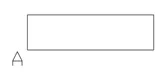
PROCEDURE: Type Rec in the command line or invoke Rectangle tool any of the methods and press Enter. Specify the first corner point A of the rectangle. Specify the other corner point @0.9,0.25 |
 |
|
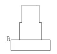
Type L in the command line then press enter to invoke line tool Specify the first point at an extension of 0.2 units to the right side from 2D reference point B Specify next point @0, 0.4 Specify next point @0.05, 0 Specify next point @0,0 .4 Specify next point @0.4,0 Specify next point @0, -0.4 Specify next point @0.05,0 Specify next point @0, -0.4 Press Esc to exit from line tool |
 |
|
Type L in the command line then press enter to invoke line tool Specify the first point at an extension of 0.05 units to the right side from reference point C Specify next point @0,1.65 Specify next point @0.3,0 Specify next point @0, -1.65 Press Esc to exit from line tool Type O in the command line then press enter to invoke offset tool Select Through and select line at point D then enter offset distance as 1 unit Then offset that line again by typing 0.05 then press enter |
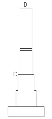 |
|
Type L in the command line and press Enter. Specify the start point at C Specify next point @-1.15, 0 Specify next point @0, -0.15 Specify next point @-1.15, 0 Press Esc to exit from line tool |
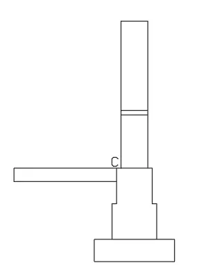 |
|
Type L in the command line then press enter to invoke line tool Specify the first point at an extension of 0.3 units to the right side from reference point B Specify next point @0, 0.15 Specify next point @0.3,0 Specify next point @0, 0.15 Specify next point @0.3,0 Specify next point @0, 0.15 Specify next point @0.3,0 Press Esc to exit from line tool Use dimension tool to measure the distance between the two points |
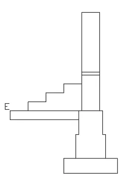 |
Tools used:
Line
Rectangle
Offset
Dimension
RESULT:
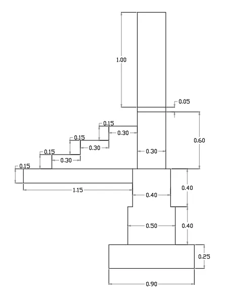
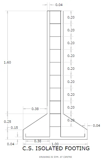
2. Cross section of Isolated footing
|
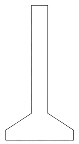
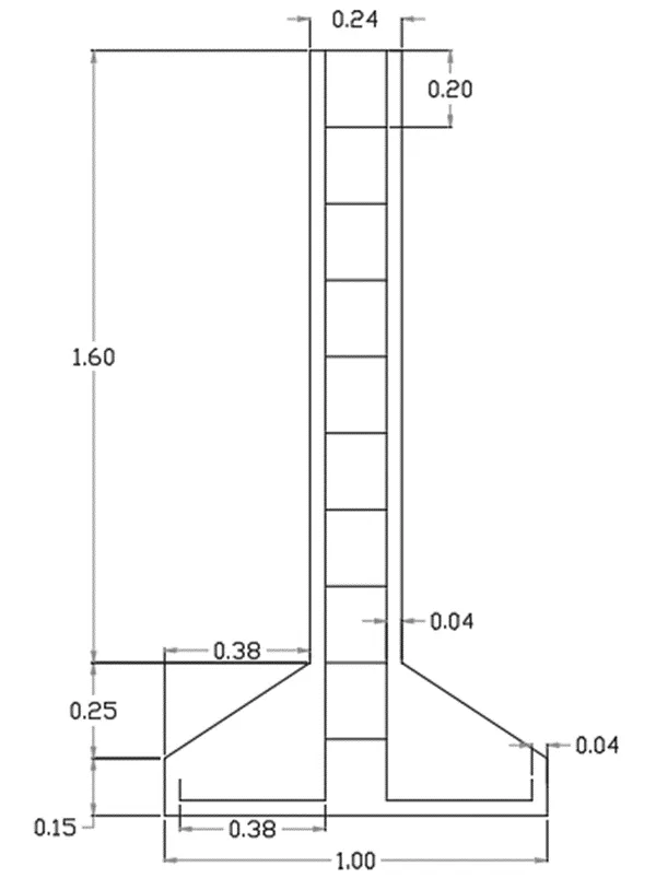
PROCEDURE: Type L in the command line then press enter to invoke line tool Click on the screen to specify the first point Specify next point @0,0.15 Specify next point @0.38, 0.25 Specify next point @0, 1.6 Specify next point @0.24, 0 Specify next point @0, -1.6 Specify next point @0.38, -0.25 Specify next point @0, -0.15 Type C then press Enter to close line tool. |
 |
|
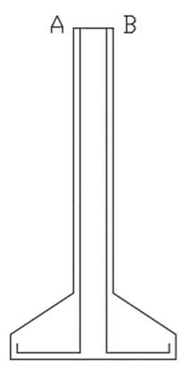
Type L in the command line then press enter to invoke line tool Specify the first point at an extension of 0.04 units to the right side from reference point A Specify next point @0, -1.96 Specify next point @-0.38, 0 Specify next point @0, 0.04 Press Esc to exit from line tool Type L in the command line then press enter to invoke line tool Specify the first point at an extension of 0.04 units to the left side from reference point B Specify next point @0, -1.96 Specify next point @0.38, 0 Specify next point @0, 0.04 Press Esc to exit from line tool |
 |
|
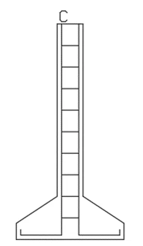
Type L in the command line then press enter to invoke line tool Specify the first point at an extension of 0.2 units to the down side from reference point C Specify next point @0.16,0 Press Esc to exit from line tool Type O in the command line then press enter to invoke the offset tool Specify the offset distance 0.2 then click Enter Select line CD then press Enter Move the cursor down side and offset the line as per requirements.
Use dimension tool to measure the distance between the two points |
 |
Tools used:
Line
Offset
Dimension
RESULT:
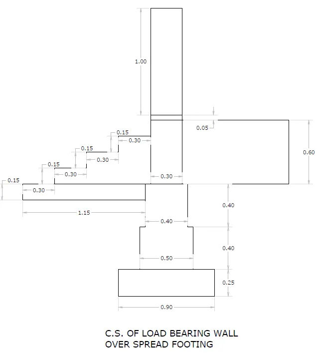
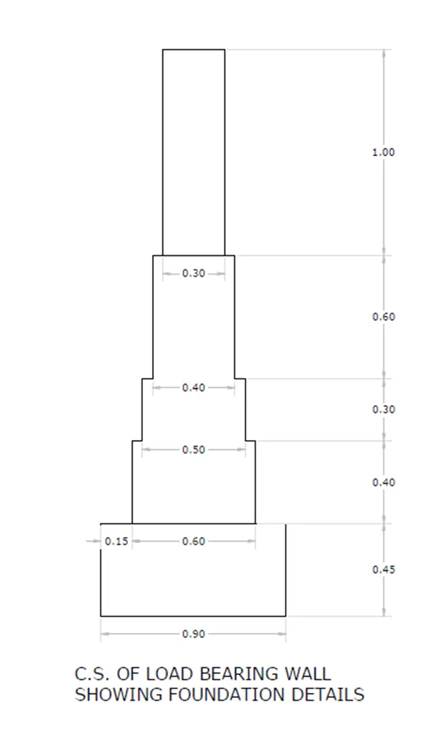
3. Cross section of Load bearing wall showing foundation details
|
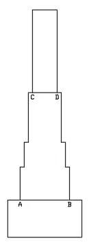
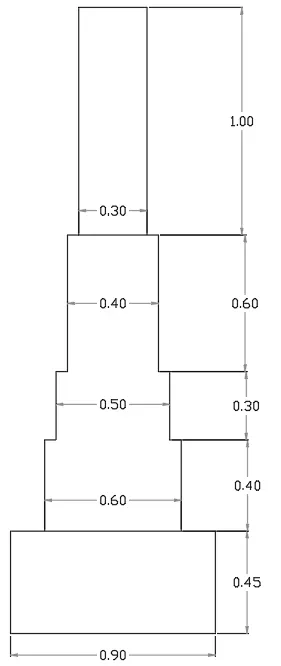
PROCEDURE: Type L in the command line then press enter to invoke line tool Click on the screen to specify the first point Specify next point @0,0.45 Specify next point @0.15, 0 Specify next point @0,0.4 Specify next point @0.05, 0 Specify next point @0, 0.3 Specify next point @0.05,0 Specify next point @0, 0.6 Specify next point @0.15 ,0 Specify next point @0, 1 Specify next point @0.3,0 Specify next point @0, -1 Specify next point @0.05, 0 Specify next point @0, -0.6 Specify next point @0.05, 0 Specify next point @0, -0.3 Specify next point @0.05, 0 Specify next point @0, -0.4 Specify next point @0.15, 0 Specify next point @0, -0.45 Type C then press Enter to close line tool. Type L in the command line then press enter to invoke line tool Select A as first point and B as second point to create a line AB Press Enter key twice and draw a line from CD |
 |
Use dimension tool to measure the distance between the two points
Tools used:
Line
Dimension
RESULT:
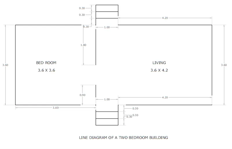
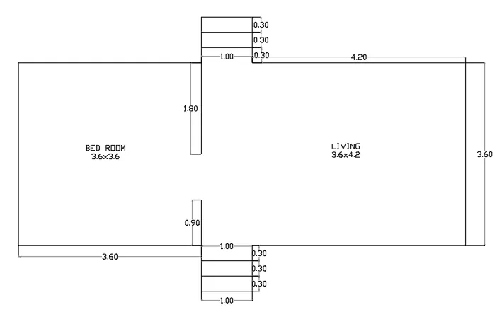
4. Line diagram of a two bedroom building
|
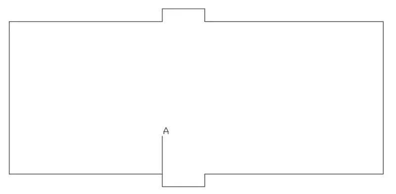
PROCEDURE: Type L in the command line then press enter to invoke line tool Click on the screen to specify the first point A Specify next point @0, -0.9 Specify next point @-3.6, 0 Specify next point @0,3.6 Specify next point @3.6, 0 Specify next point @0, 0.3 Specify next point @1, 0 Specify next point @0, -0.3 Specify next point @4.2, 0 Specify next point @0, -3.6 Specify next point @-4.2, 0 Specify next point @0. -0.3 Specify next point @-1, 0 Specify next point @0, 0.3 Press Esc to exit line tool |
 |
|
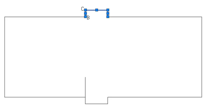
Select 3 lines as shown in image and type CO to invoke copy tool Select B as base point and C as second point Repeat the same steps to create steps on other side also |
 |
|
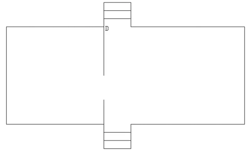
Type L in the command line then press enter to invoke line tool Click on the screen to specify the first point D Then make sure Ortho mode on and move cursor down side type the dimension 1.8 and press Enter |
 |
Use dimension tool to measure the distance between the two points
Tools used:
Line
Copy
Multiline Text
Dimension
RESULT:
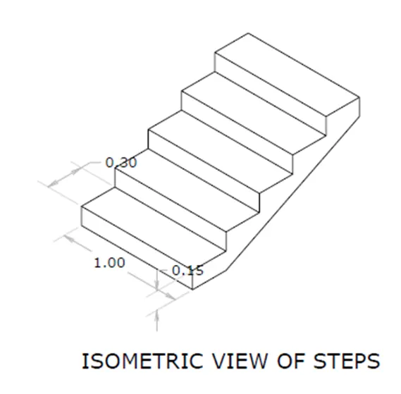
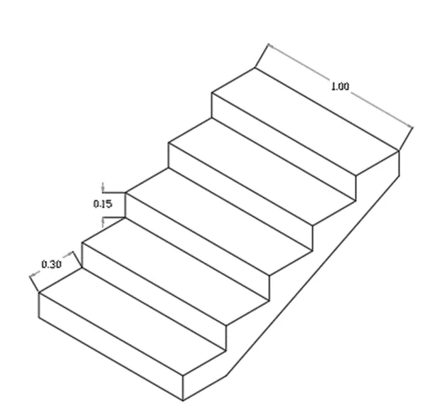
5. Isometric view of steps
|
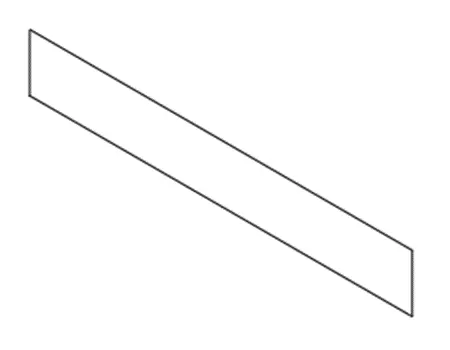
PROCEDURE: Type the DS in command box & press enter. In snap & grid palette select snap type as isometric snap & click on ok, cursor changes to isoplane left or click on isometric drafting on status bar & make it on. Click on the ortho made on status bar to restrict directions to 90 & 30 inclined to x axis. Choose line tool & specify first point. Move the cursor up & type distance 0.15 & press enter. Position the cursor in left up, type the distance 1 in command box press enter. Position the cursor in downward direction, type distance 0.15 & press enter & choose the close option in command box. |
 |
|
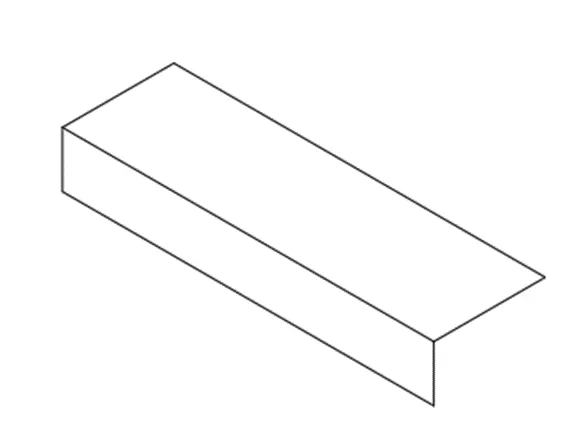
Using F5 key change the isoplane left to isoplane top or change it by using isometric drafting setting of status bar. Again, choose the line tool & specify the first point. Position the cursor in right up direction type distance 0.3 & press enter. Position the cursor in left up direction type distance 1 & press enter. Position the cursor in left down direction type distance 0.3 & press enter. |
 |
|
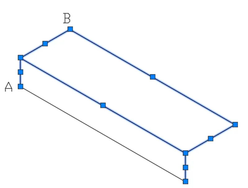
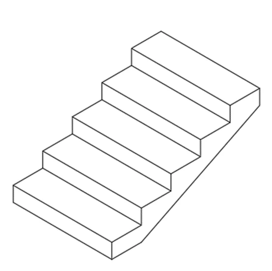
Choose the copy tool & select the lines as shown & choose base point as A corner of first step. Specify second point as B. Repeat the same procedure for three more times & create five steps. |
 |
|
Using F5 key change the isoplane top to isoplane right. Choose the line tool & from corner point of topmost step draw line in downward direction having length of 0.15 unit. With the line tool draw line of length 0.3 from first corner point of first step in isoplane right & join the above two draw line using line tool. |
 |
Use dimension tool to measure the distance between the two points
Tools used:
Line
Copy
Inclined Dimension
RESULT:
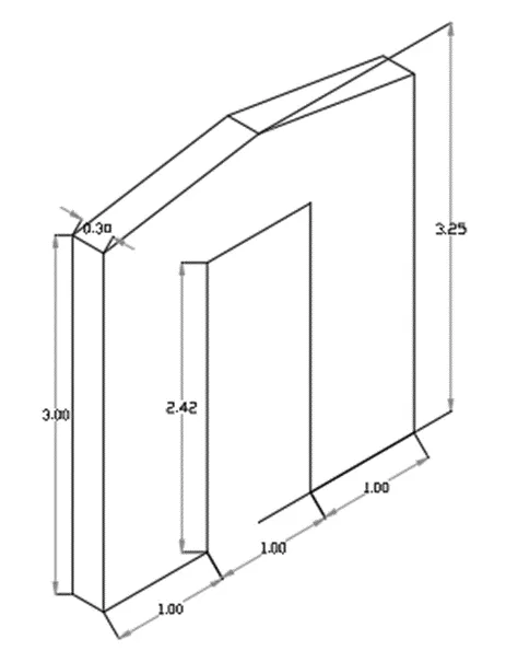
6. Isometric view of gable wall
|
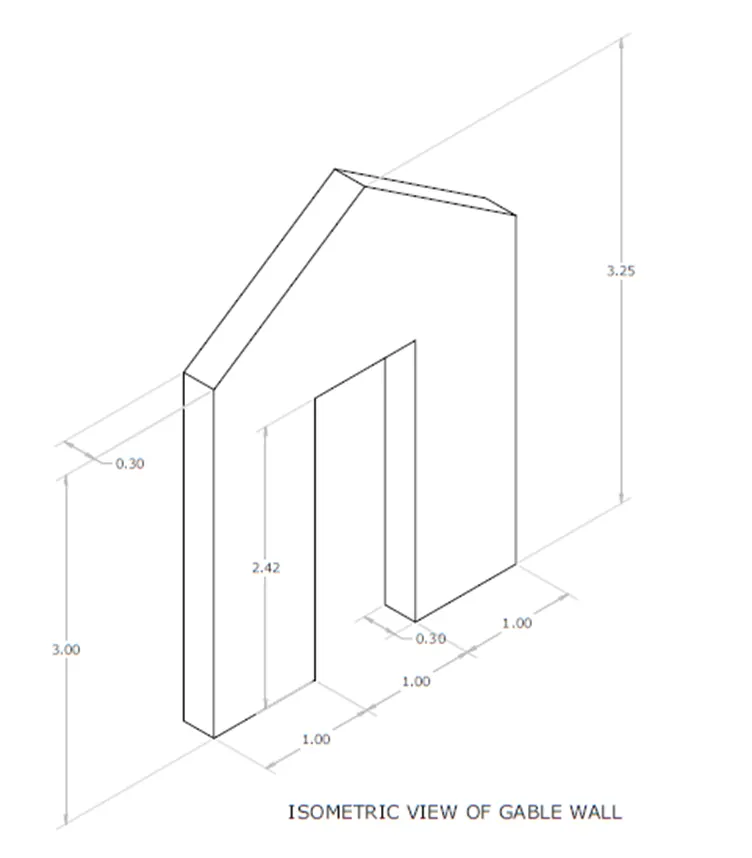
PROCEDURE: Type the DS in command box & press enter. In snap & grid palette select snap type as isometric snap & click on ok, cursor changes to isoplane left or click on isometric drafting on status bar & make it on. Click on the ortho made on status bar to restrict directions to 90 & 30 inclined to x axis. Select isoplane left Choose line tool & specify first point. Move the cursor up & type distance 3 then move cursor to left & type 0.3 Move the cursor down & type distance 3 then close line tool |
 |
|
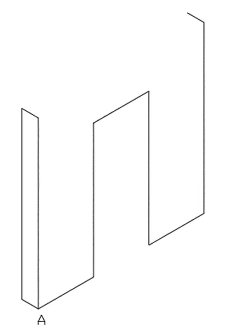
Select line tool and specify first point as A and switch to isoplane right Move cursor to right & type 1 then cursor up & type 2.42 Move cursor to right & type 1 then cursor down & type 2.42 Move cursor right and type 1 then cursor up & type 3 Change the mode to isoplane left mode Move cursor to left & type 0.3 then Enter |
 |
|
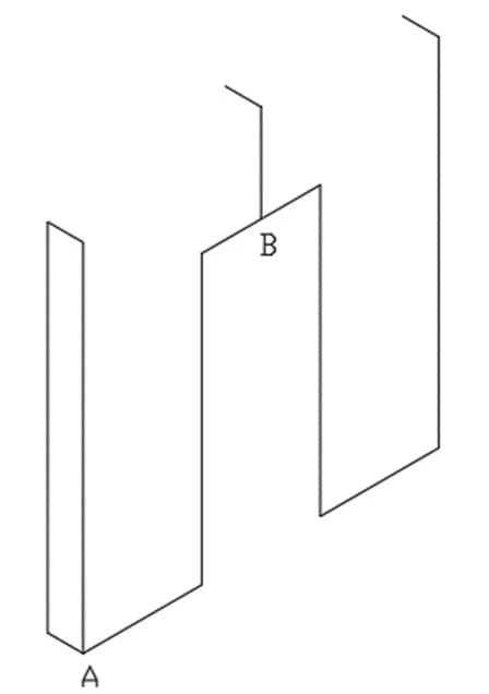
Select line tool Specify midpoint B as first point of line Move cursor up & type 0.83 then left and type 0.3 |
 |
|
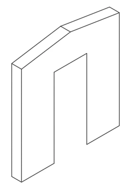
Switch to Isoplane top and join the top lines Delete unnecessary line |
 |
Use dimension tool to measure the distance between the two points
Tools used:
Line
Inclined Dimension
RESULT: