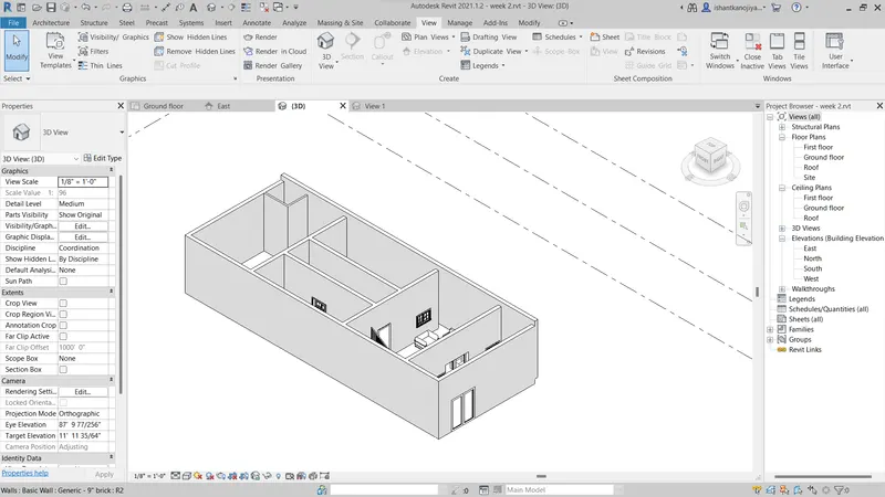
Creating Levels, Grids, Layout and model elements for a residential unit using REVIT
1) What is BIM? Summarize the features of BIM and the benefits of using BIM over 2D CAD tools.
- BIM is a new process and methodology by which a team of architects, engineers, and conductors work collaboratively to design and build a commercial building utilizing the same database and computer model. This allows the team to analyze and visualize design decisions long before a project even breaks ground, at its core, BIM offers a digital representation of the real facility, including function system and aesthetics. It does so while being a shared resource from start to finish across multiple disciplines participating in the design and build.
Features of using BIM over 2D CAD tools are-:
- Early detection of a collision
- Faster design and construction
- Improvement of OSH
- Higher quality of performed work
- Better communication in the project
- Reducing delays and errors
- Competitiveness
- Mitigate Risk and Reduce Cost.
- Improved Scheduling/Sequencing
- Visualize Projects in Preconstruction.
- ETC
Benefits of BIM:-
- Better planning and design: BIM should enable a completed building and all its related M&E services and systems to be visualized on screen before ground is broken. This information allows better planning and design for the architect that enables available space and resources to be used more effectively.
- Easy design changes: the model is shared, so users can create changes to the one BIM model. This can be at set times ready for follow-up design team meetings or even in real-time, so everyone is working with up-to-date information and a collaborative workflow can be established.
- Minimal rework on site: BIM facilitates the visibility of potential problem areas and allows errors to be corrected through model lash detection before they are physically committed. This reduces the need for costly site rework and revision resulting in both labor and material savings.
- Prefabrication: BIM allows contractors and subcontractors alike to visualize the project, allowing time to more easily and precisely prefabricate work offsite, which can save time and money through better productivity controls in the manufacturing environment away from a construction site.
- Free software is available: all parties involved at every level of the project can use the completed model, with the use of free 'view only' software. This has been used by Sotham with great effect on-site with portable tablets, allowing the supervisor instant access on-site to the model for coordination of trades. Viewing a 3D model is much more informative than looking at and interpreting various 2D drawings.
- Lifetime information to the end-user; for those who embrace BIM, the model can be populated with a wealth of easy to read and find data. Each system and even individual component in the model can contain information of size, color, supplier, and even maintenance data. Long gone are the days of scanned or photocopied manufacturers' data, resulting in poor quality generic and often hard-to-find information, contained in ring binders taking up valuable storage space.
2) Understand the concept of Categories, Families, Elements, Instances in Revit. Go to Insert Tab, choose a category. Pick a family and element. Understand the instances and insert them into the Revit model.
- The 3 kinds of families in Revit are system families, loadable families, and in-place families. Most elements that you create in your projects are system families or loadable families. Loadable families can be combined to create nested and shared families. Non-standard or custom elements are created using in-place families.
System Families
System families create basic elements that you would assemble on a construction site. Examples:
- Walls, roofs, floors
- Ducts, pipes
Loadable Families
Loadable families are families used to create the following:
- Building components that would usually be purchased, delivered and installed in and around a building, such as windows, doors, casework, fixtures, furniture, and planting
- System components that would usually be purchased, delivered and installed in and around a building, such as boilers, water heaters, air handlers, and plumbing fixtures
- Some annotation elements that are routinely customized, such as symbols and title blocks
In-Place Families
In-place elements are unique elements that you create when you need to create a unique component that is specific to the current project. You can create in-place geometry so that it references other project geometry, resizing or adjusting accordingly if the referenced geometry changes. When you create an in-place element, Revit creates a family for the in-place element, which contains a single-family type.
Creating an in-place element involves many of the same Family Editor tools as creating a loadable family.
- Categories are an import tool within Revit for identifying the inferred type of an element, such as anything in the Walls category should be considered as a wall. The API exposes access to the built-in categories within Revit via the Document.
- Elements in Revit are also referred to as families. The family contains the geometric definition of the element and the parameters used by the element. Each instance of an element is defined and controlled by the family. Model elements represent the actual 3D geometry of the building.
- Instance = An item from a catalog that is installed in your facility where the properties for that asset are unique to its installation.
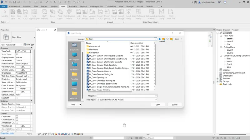
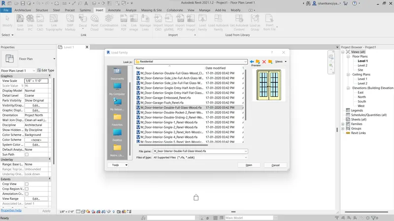
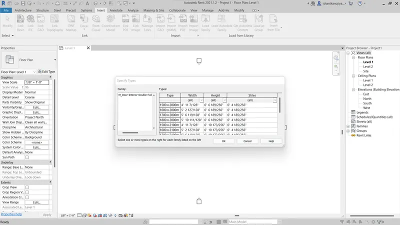
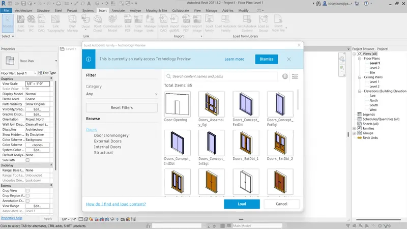
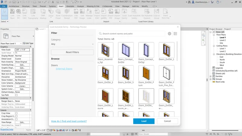
Go to Insert Tab, choose a category. Pick a family and element.
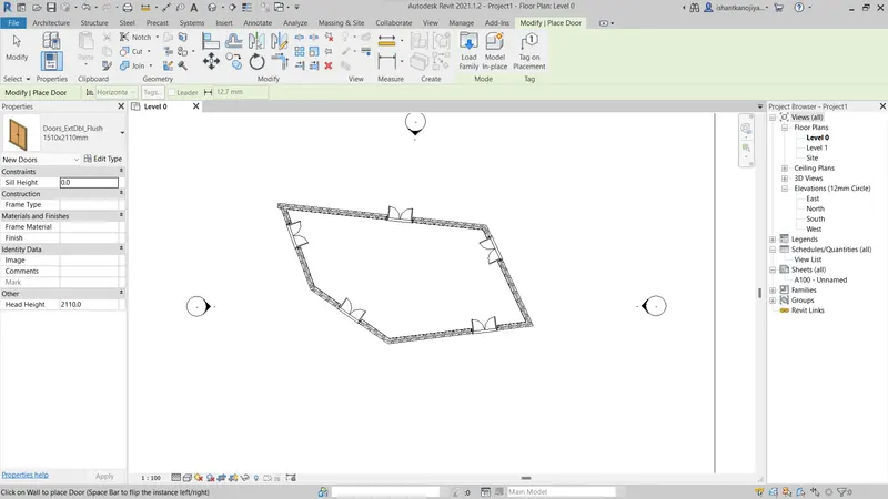
- Go to Insert tab, select Load Family, select categories like door, select types of doors, specify types, specify point
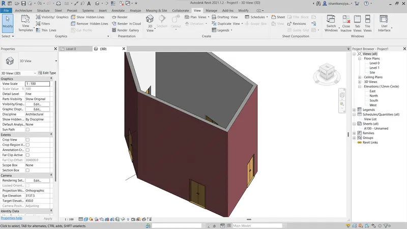
3) Setting up a Project – Open a project file with an architectural template. Save the file with an appropriate name. Set up the project units to Imperial / Metric based on your convenience of modeling. Complete the project information under the Manage tab. Set up the maximum backups for project files to 3
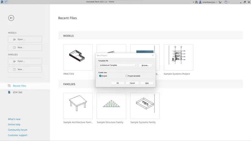
- Select new models, select template, Architectural template, press ok
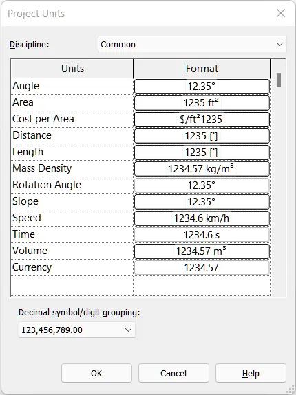
- Go to the project manager tab, select project unit, select units as per convenience
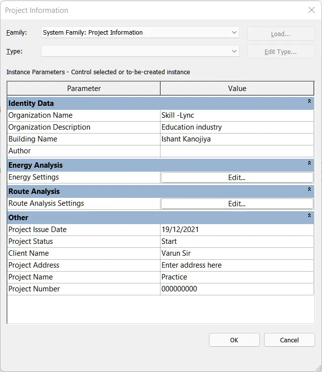
- Select project Information, Fille information
- Select a file, select save as, select library , family, press ok
4)
AIM:- Understand the concept of Levels and Grids. Follow the naming and conventions. Create the following Levels: ( Convert to metric equivalents if metric is your units)
Ground Floor @ 0’
First Floor @ 10’
Second Floor @ 20’
Roof @ 30’
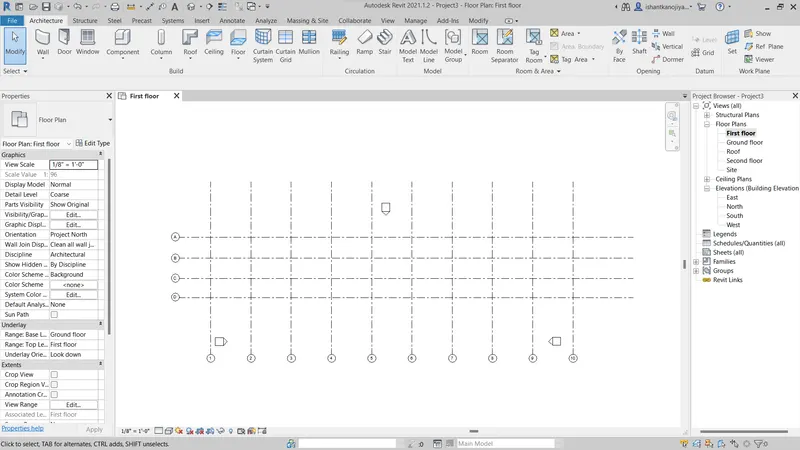
Grids Transverse Grids A, B, C,D, E @ 10’ spacing
Longitudinal Grids from 1 to 10 @ 20’ spacing
Procedure:-
- Select East in elevation, select level 0, edit level 0 to Ground floor
- Same as level 2 to the First floor
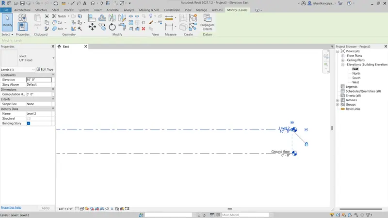
- Select level tool, select pick line, specify offset 10', select first floor, and drag simply upward, the level is generated so to rename it as the Second floor
- SAME as for ROOF

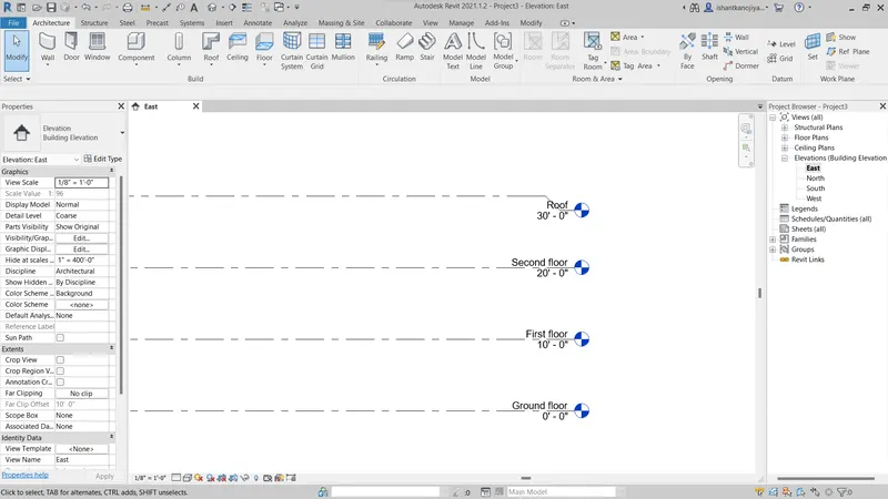
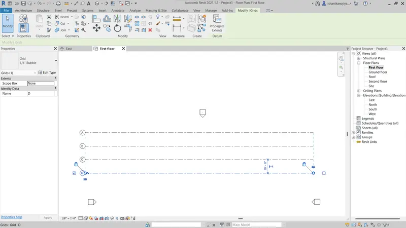
- Select grid, select the first floor, drag the cursor left to right, offset 10' , pick line for second grids, and continue
- same as longitudinal grids but offset is 20'
5)
AIM-: 3D modeling of the residential unit – From looking at your house / or a place you aspire. Create a conceptual layout of the residential unit. You can measure using a tape or
you can access your residential plan to create a similar layout.
PROCEDURE:-
- Select new model, select template, press ok
- Make levels> select east >select level>select pick as level 1 as ground floor> offset distance 12'> cursor drag upward > name as first floor>same as Roof floor
- Edit name level 1 to Ground Floor
- Select wall> go to ground floor> select lines >sketch the plan by dragging the cursor/ model line
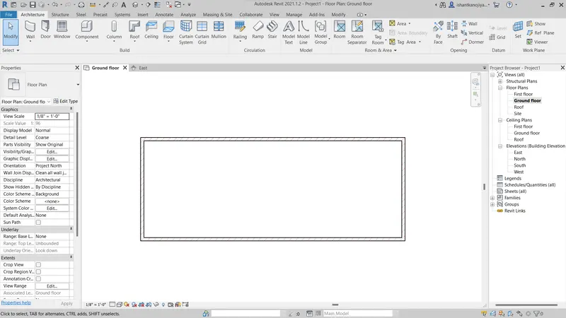
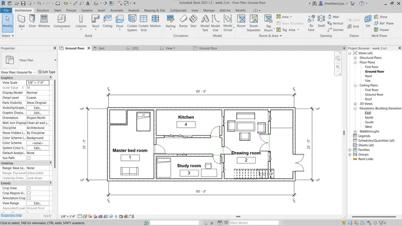
- Conceptual layout
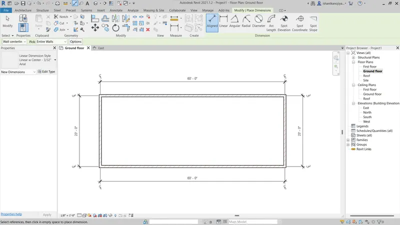
Result:-
6)
AIM:- In the layout created to draft the level of details you are planning to include – Dimensions of room, components you plan to add in the residential unit.
Procedure:-
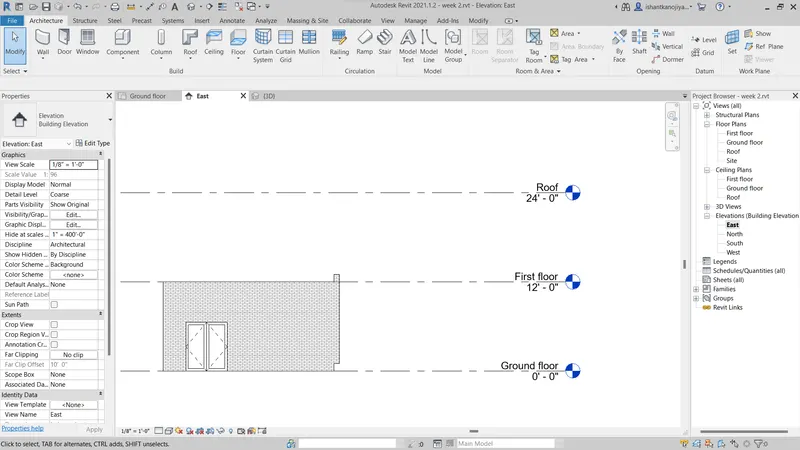
- Select east >rename level 1 to the ground floor
- select level option> select pick lines > offset distance 12'> drag the cursor upward to the ground level and rename it> same as Roof
- select tag room >drag the cursor into the closed boundary >press enter >rename it
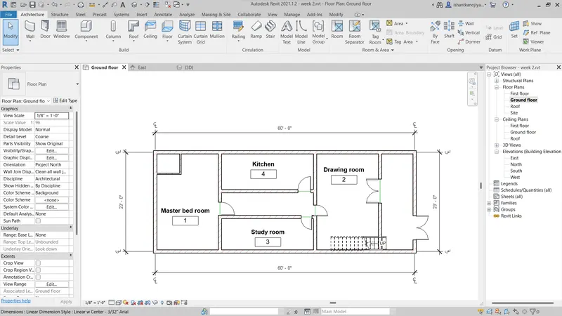
Result
7)
AIM:- Identify the residential model elements such as Door, Windows, Tables, Chair, Couch, Bed, Lamps from the library and insert them into the model. Save the project for use
for Assignment 3
Procedure:-
- select door command>select category >select dimension>press ok> drag the cursor where you place >press enter
- select windows command> select category >select dimension>press ok>drag the cursor where you want to place >press enter
- the components like tables, chair, couch, bed, lamps from>component command>select families >select category>select dimension>press ok>drag the cursor where you want press enter
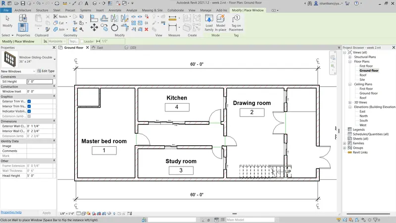
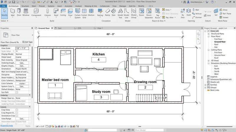
Result