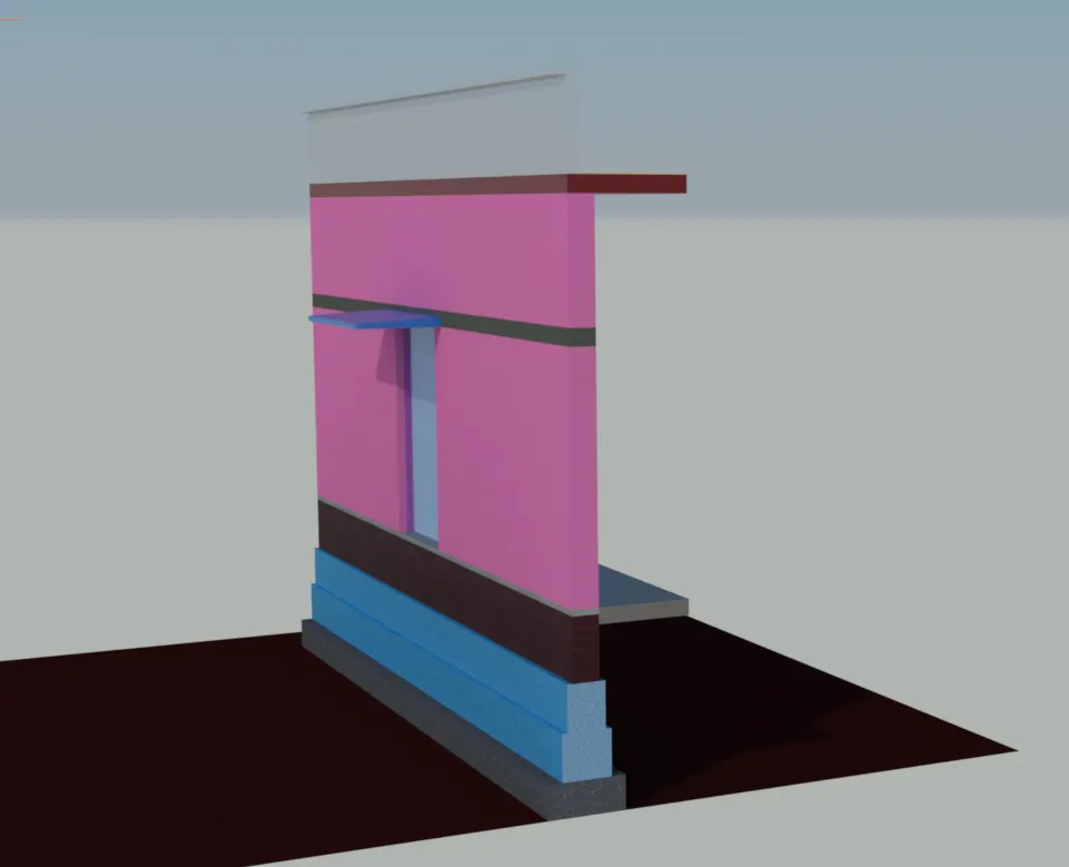
Creating 3D Isometric view of various structural elements in AutoCAD
AIM:- Creating 3D Isometric view of various structural elements in AutoCAD
Create a 3D Isometric View of the building with plan and elevation given.
stepwise procedure:-
command or tool used:
- For 2D:
- line
- offset
- trim
- explode
- rec
- move
- copy
- For 3D:
- Boundary
- region
- EXT
- pressfull
- subtract
- union
- move
- 3D rotate........ETC.
Draw the plan in 2D by use of 2D Drafting and Annotation as shown below diagram/plan drawn.
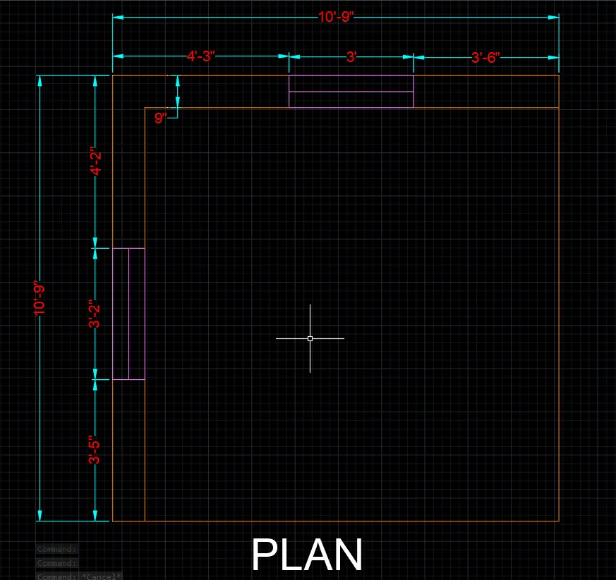
- click on the layer properties
- crate the layers for 3D drawing like 3D wall, 3D window frame, 3D window mullion ..... etc
- take the 3DROTATE command
- select the elevation 1 and 2
- keeping the cursor on the vertical plane and rotate it
- move the elevation parallel to tha plan
- create the windows by use of BO, EXT , SUB, Move command
- place in required position
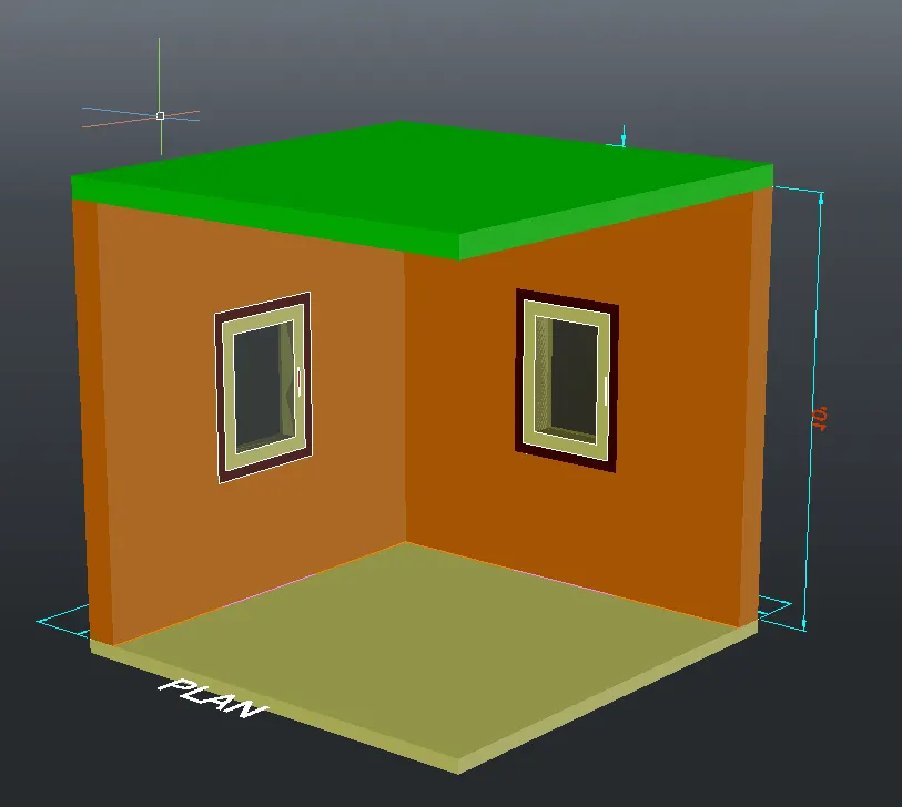
- create the views by orbiting the plan by 3D ORBIT command as below:
View 1:
View 2: Elevation A.
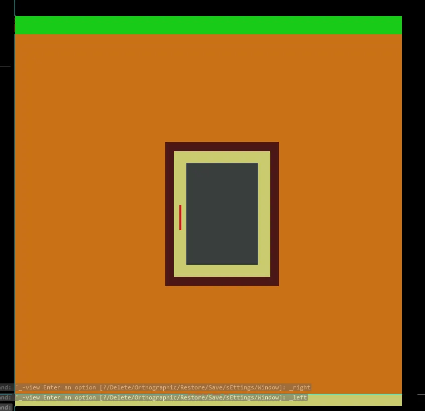
View 3: Elevation B.
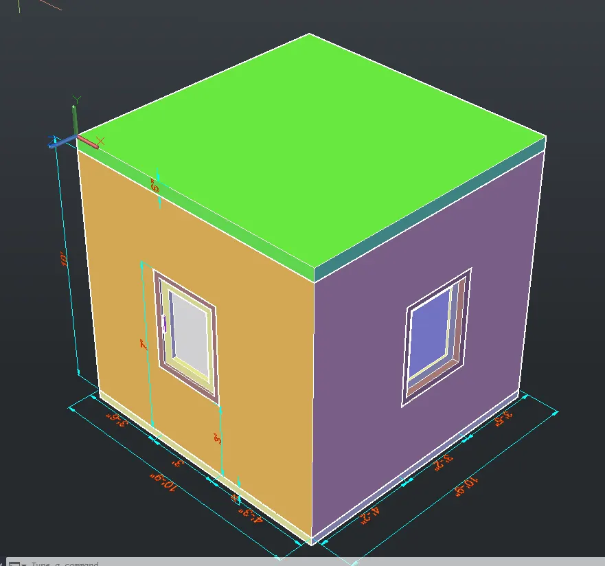
Rendered Output-:
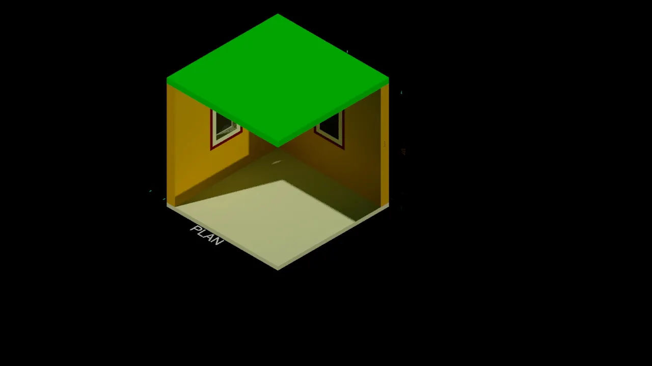
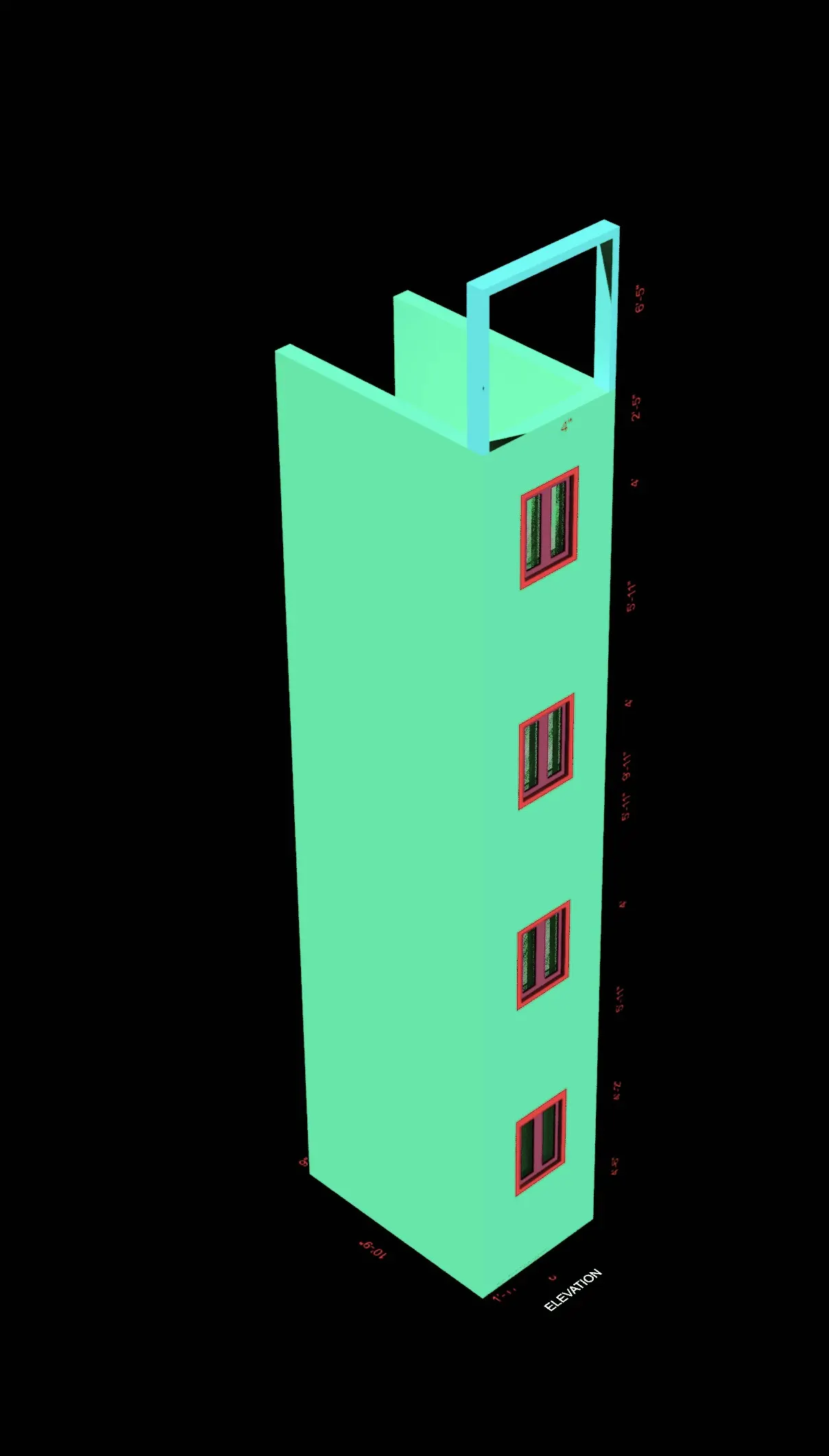
2.Create the 3D View of the Building Façade as given in the plan and elevation. Also, see the detail of the window.
stepwise procedure:-
command or tool used:
For 2D:
- line
- offset
- trim
- explode
- rec
- move
- copy
For 3D:
- Boundary
- region
- EXT
- pressfull
- subtract
- union
- move
- 3D rotate........ETC.
- Draw the plan in 2D by use of 2D Drafting and Annotation as shown below diagram/plan drawn.
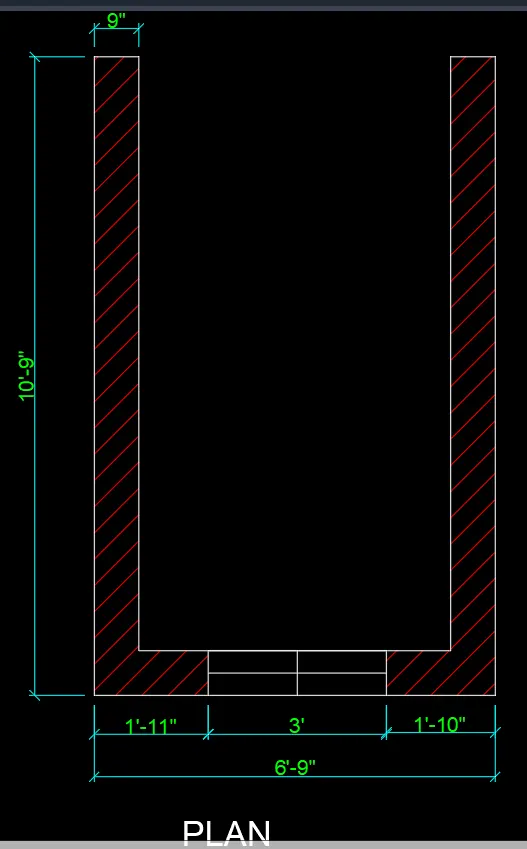
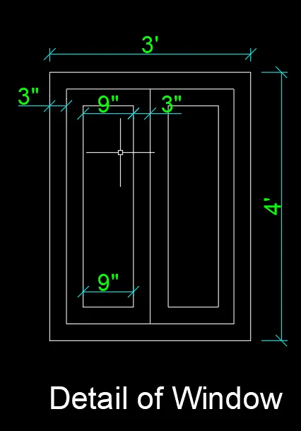
- create the plan for the window
- click the layer properties and create the layers for the window and wall also
- Ext the window frame, mullions, pannels, by keeping the particular layer as set current and with that do subtract simultaniously.
- Keep the workspace in 3D modelling
- keep the SE isometric unsaved view
- keep the visual style as u have
- see the result in below view:
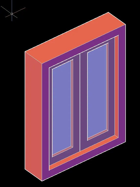
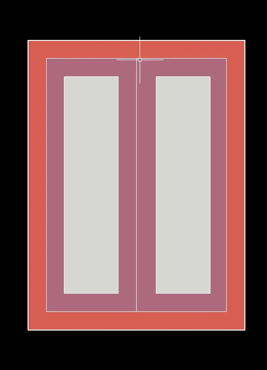
- From the plan of the room
- create the boundary by using the BO command
- set the 3D wall layer as set current
- take EXT command
- extrude the wall at the height of 8'8''
- also do same up to height of 4'6''
- simmilary create the profile of the elevation by using Ext ,pressfull , union command
- copy the window
- select the base point as any corner of the window
- take the copies in particular window opening in the elevation
- see the result as in below view:
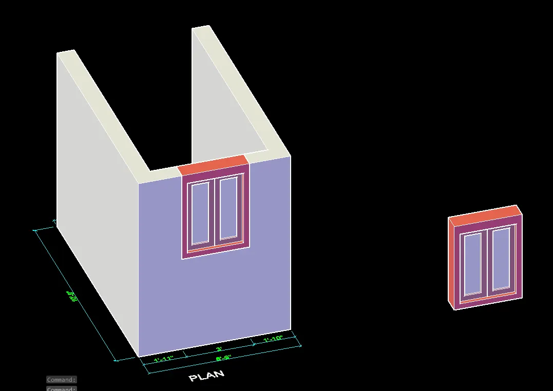
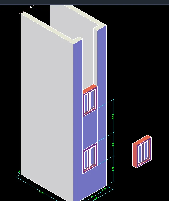
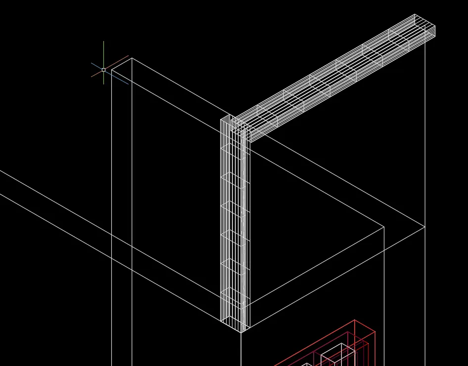
View 1:
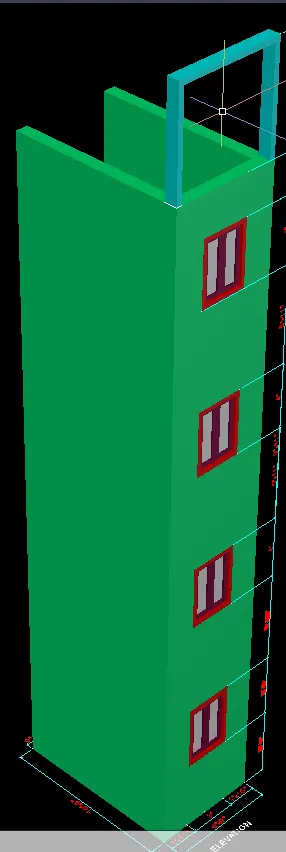
- Take the UCS on the top of the wall
- create the style as see in above view by using rec , 3D poly line, Sweep command
View 2:
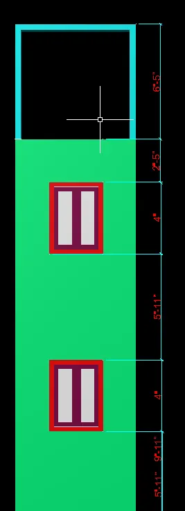
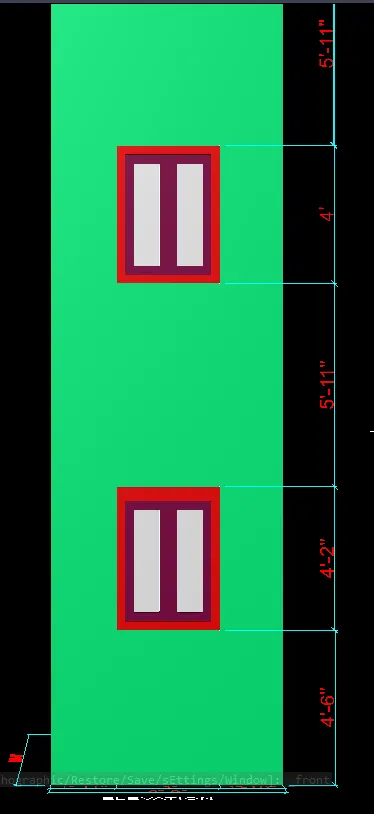
Rendered output-:
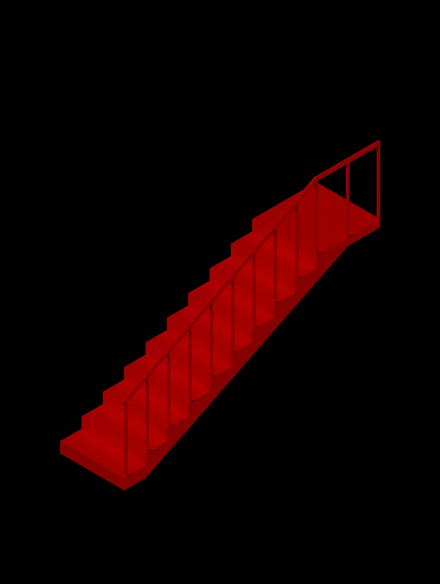
3.Create the ismoteric 3d view of a stair with railing as shown in the plan and elevation. Assume the size of the balustrades and the hand rails.
stepwise procedure:-
command or tool used:
For 2D:
- line
- offset
- trim
- explode
- rec
- move
- copy
For 3D:
- Boundary
- region
- EXT
- pressfull
- subtract
- union
- move
- 3D rotate........ETC.
- Draw the plan in 2D by use of 2D Drafting and Annotation as shown below diagram/plan drawn.
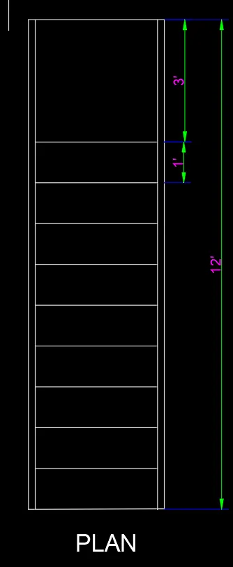
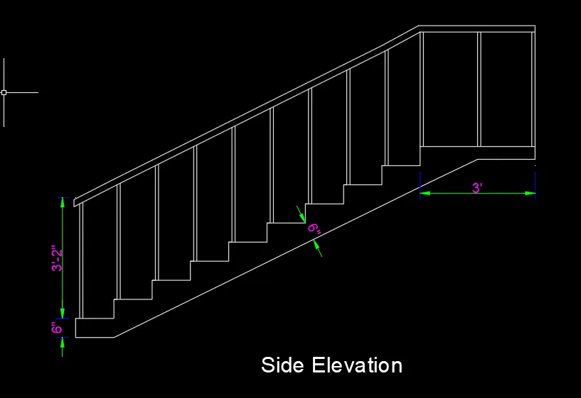
- Keep the workspace in 3D modelling
- keep the SE isometric unsaved view
- keep the visual style as u have
- create the boundary using BO command
- take the EXT command
- extrude the staircase with 3' at inward
- change the visual style to conceptual
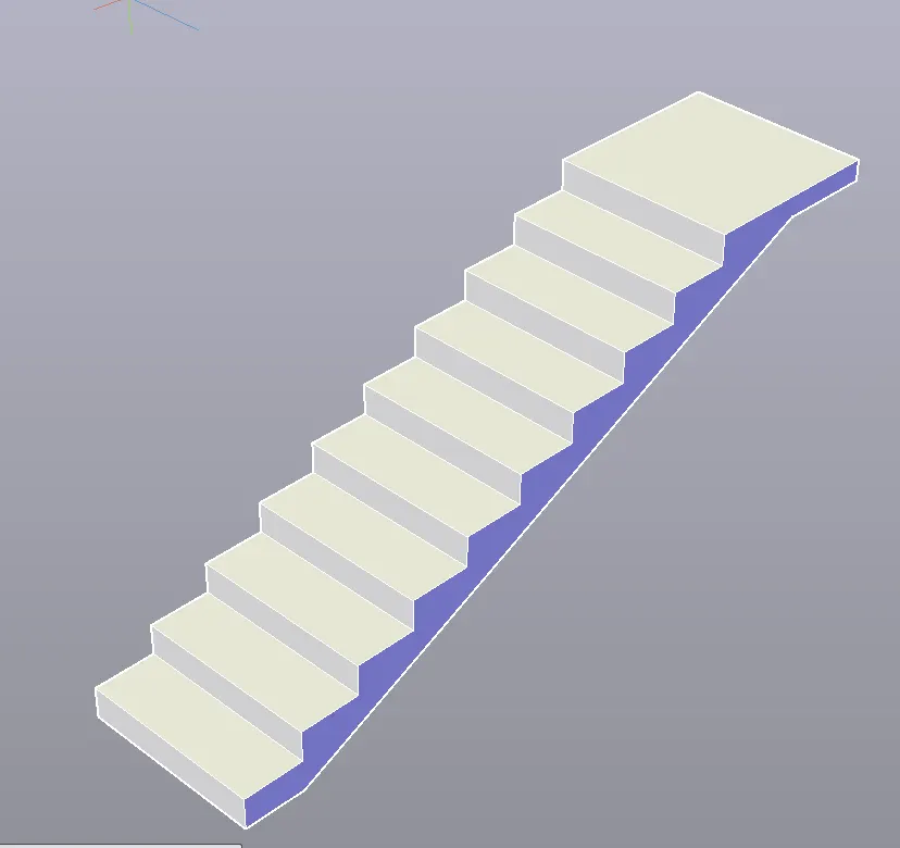
- To draw the baluster and handrail
- Take the square command and draw the square size of 1"x2"
- copy the square and place it on the top of the stairs from the 1" distance from the edge of the strairs.
- Then use the Extrude command to extrude the square to the height of 3' represented as baluster.
- Then use line command to draw the square of size 1"x2" for the hand rail.
- use SEG command to make a segment face on the square.
- draw a signle line that connects all the baluster.
- use sweep command to make a handrail using the path of a single line and sqaure.
View 1:
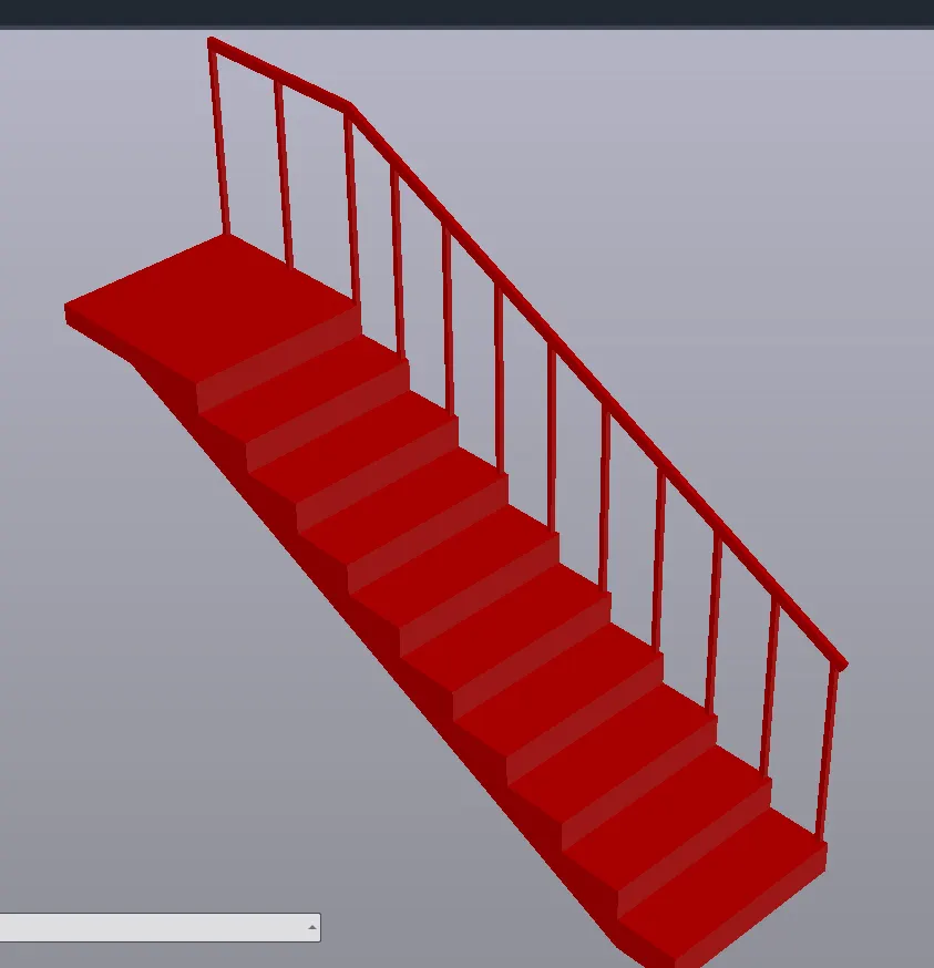
View 2:
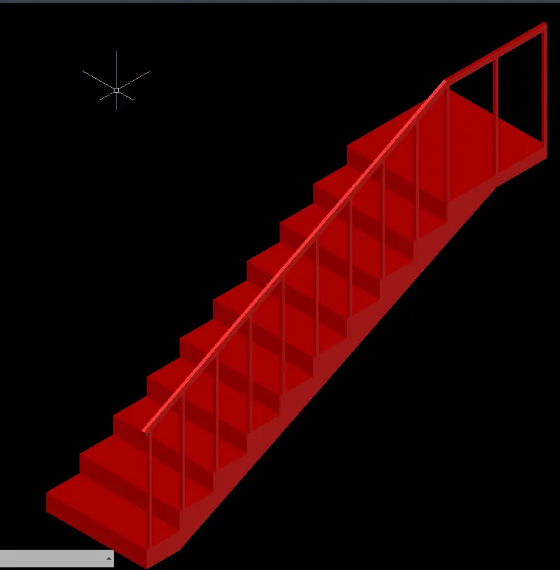
View 3:
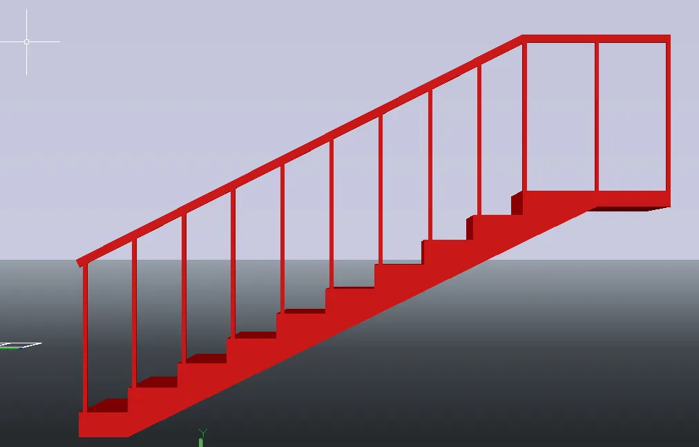
Rendered output-:
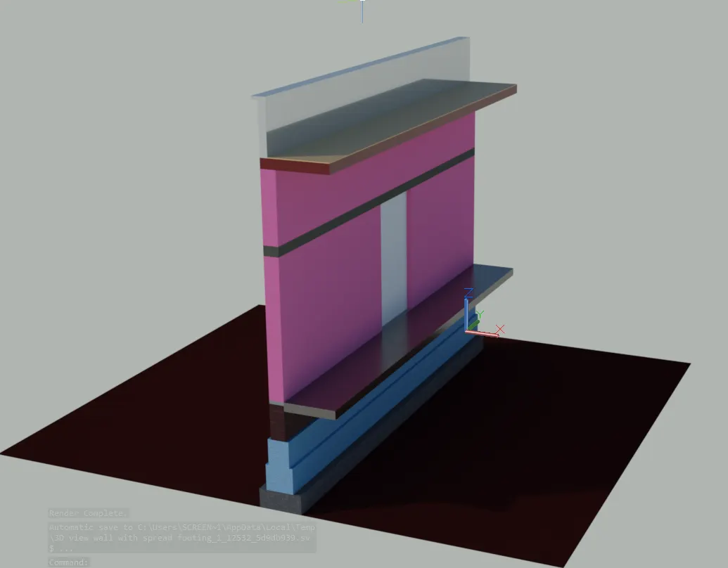
4-:Aim: To create the 3D view of a Wall with spread footing
Introduction: To create the 3D view of a Wall with spread footing. By using AutoCad
Procedure:
Step1:
- First we open the autocad and set the maximum limit and minimum limit.
- Next we set the units as decimal and take the precision as 0.
- Next we have to draw plan of wall with spread footing with given dimensions as shown in the below figure.
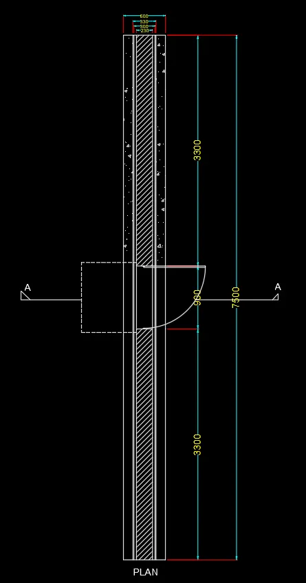
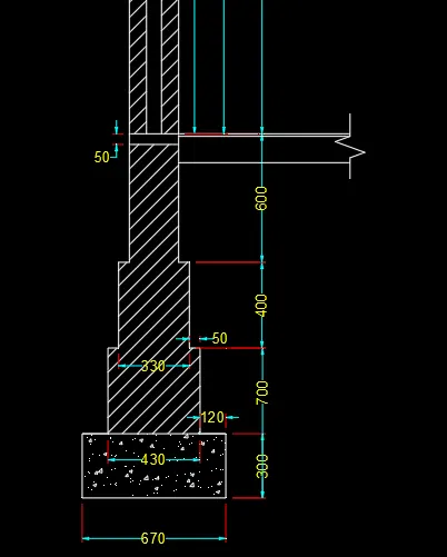
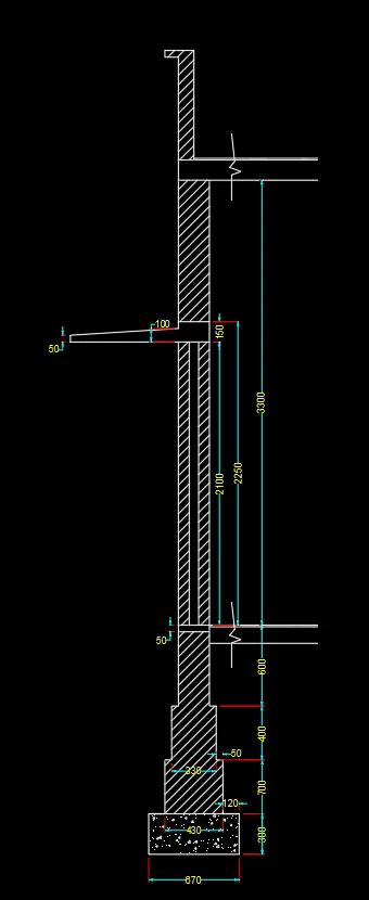
Step:-2
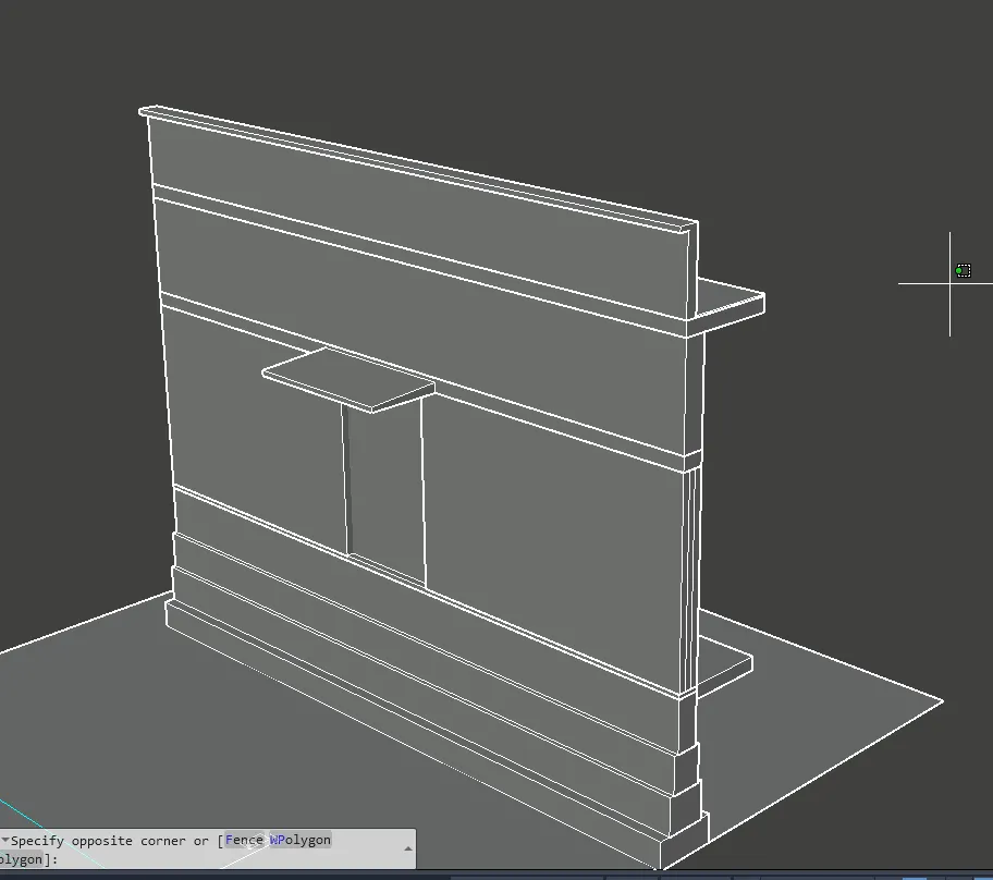
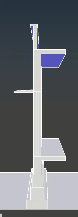
Next we draw the 3d isometric view of the wall with spread footing using the extrude command as shown in the below figure.
Step:-3
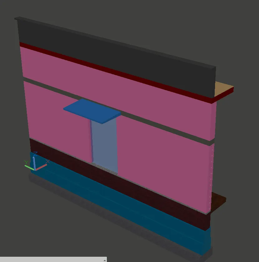
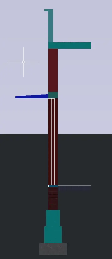
Next we provide the different materials for the wall with spread footing, as shown in the below figure.
Step:-4
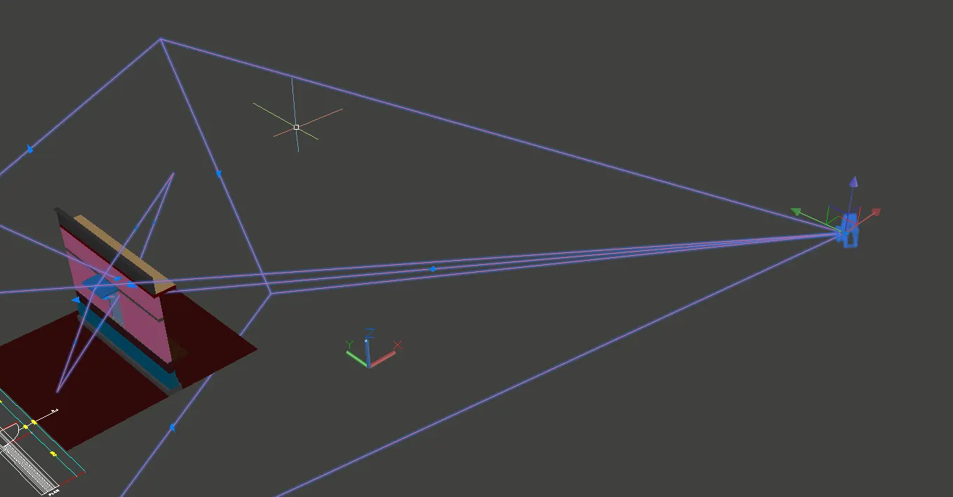
We select the camera and put it in the required postion and then press enter.
Next click on the camera then the small tab will appears at the top of the left corner, as shown in the figure.
Step:-5
Finally we select the render option and then slowly it changes to the rendering view as shown in the below figure.
RESULT:-