layout, Hatching of Architectural elements and sectional view of an Industrial Building in AutoCad
1.AIM: To create the kitchen layout and providing the hatches to it using Autocad.
Introduction:
kitchen layout is the most important part of designing your perfect kitchen.
It’s the layout that will determine how you cook, how you eat and how you socialise.
So whether you’re totally remodelling the kitchen, buying new appliances or simply replacing the cabinets, we’ve included the top five most common kitchen layouts to help inspire you.
Commands used:
Limits command
Line command
Offset command
Hatch command
Dimlinear command
Dimstyle command
Units command
Extend command
Fillet command
Trim command
Join command
Line weight command
Line type command
Object snap command
Procedure:
Aim: To create the layout of the kitchen and providing hatches to it using the autocad in detail.
Introduction:
kitchen layout is the most important part of designing your perfect kitchen.
It’s the layout that will determine how you cook, how you eat and how you socialise.
So whether you’re totally remodelling the kitchen, buying new appliances or simply replacing the cabinets, we’ve included the top five most common kitchen layouts to help inspire you.
Step:-1
Below counter plan:
First we have to draw the line horizontally with the length of 4300mm.
Next draw another line from the previous line with the length of 3200mm vertically upwards.
Next again we draw the line from previous line with the length of 4300 mm horizontally backwards at the top.
Next we have to join the first line and the last line which we have drawn previously.
Next offset the four sides with the offset of 20mm outside.
Next we have to offset the line inside with the offset command with the length of 600mm, including the fridge.
Afterwards we draw the fridge separately with other dimensions in the kitchen layout.
Next we need to draw the line opposite side to create the parts of kitchen.
Next divide the seven parts downside with different dimensions compared to the upper side portion.
Next leave the space left and right corners with the length of 35mm at the top and bottom.
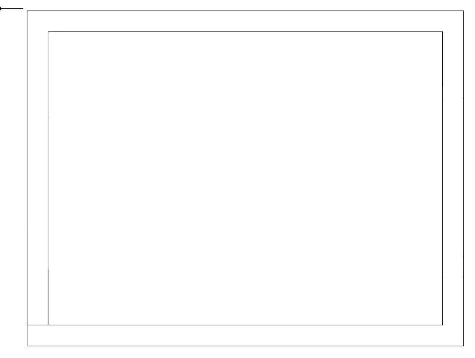
Next put the dimensions for the every part in the diagram.
Next indicate the door as D2.
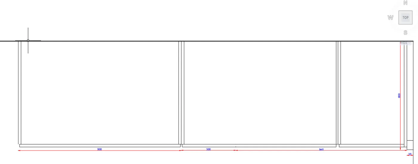
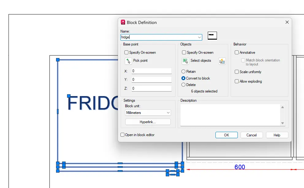
Next we have use the single text command and indicate the parts where ever it requires with single text command.
And put the dimensions for the every part in the diagram.
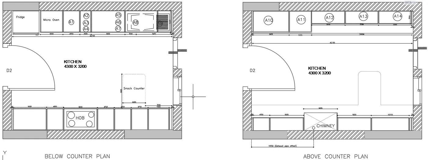
Next draw the snack counter with the length of 600mm and width of 900mm, And draw the circles to create the hub in the middle at the bottom of the kitchen.
And create the windows using the line command and trim command, which is shown in the below figure.
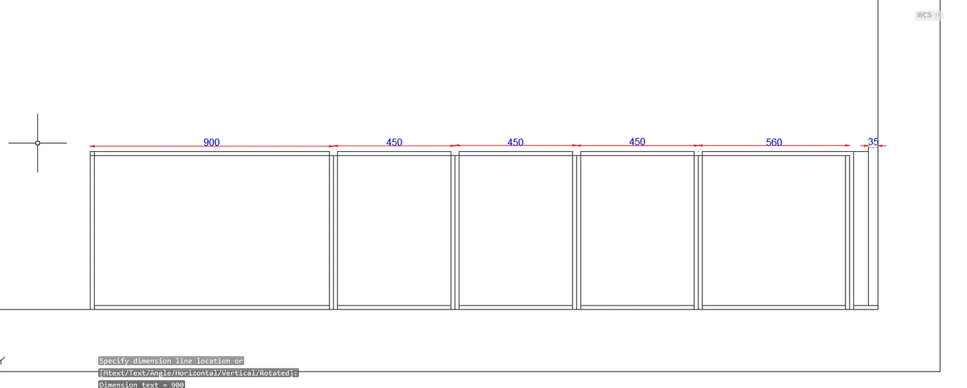
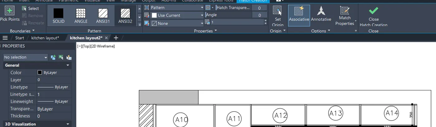
Next use hatch command to hatch the outer wall of the kitchen layout as shown in the image below.
From the below counter plan,the above counter can be drawn as show in the figure below.
2.AIM: To create the elevation of the plan created in the challenge7.
And need to apply proper hatchs in the walls, doors, windows, and other architectural elements.
INTRODUCTION:-
Elevation drawings are a specific type of drawing architects use to illustrate a building or portion of a building.
An Elevation is drawn from a vertical plane looking straight on to a building facade or interior surface.
This is as if you directly in front of a building and looked straight at it.
Elevations are a common design drawing and technical architectural or engineering convention for graphic representation of architecture.
Elevation drawings are orthographic projections, This means they are not drawn in perspective and there is no foreshortening.
COMMANDS USED:-
Limits command
Line command
Offset command
Hatch command
Dimlinear command
Dimstyle command
Units command
Extend command
Fillet command
Trim command
Join command
Line weight command
Line type command
Object snap command
Rectangle command
Zoom command
PROCEDURE:-
Step:-1
First we have to open the autocad and set the limits.
Next we use the zoom command and press enter.
Comming to the drawing the elevation of the residential buiding, first we draw the horizontal line using the line command X-LINE.
Next we need to draw the another line from the previous line vertically using the line command X-LINE.
Next we have to draw the line horizontally backwards from previous line at the top.
Next we draw the line downwards vertically, by drawing the last line the rectangle will be formed.
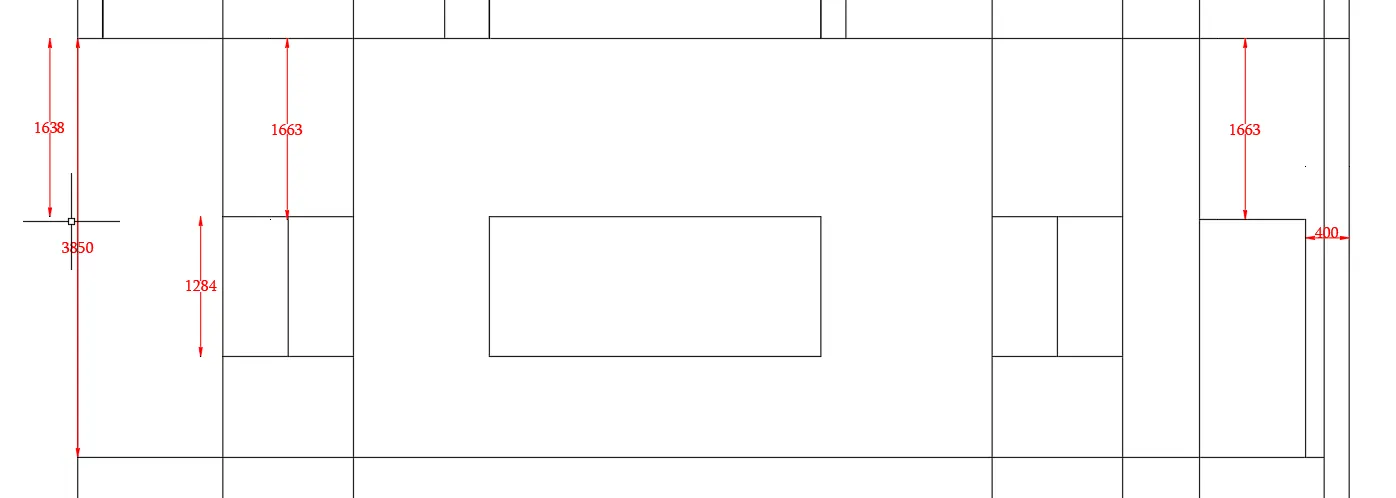
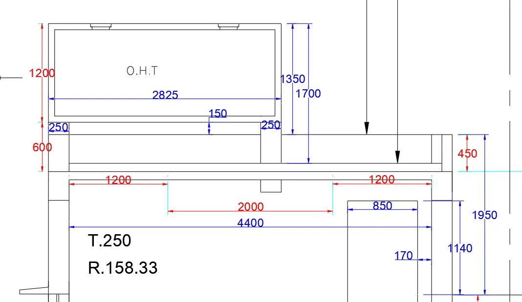
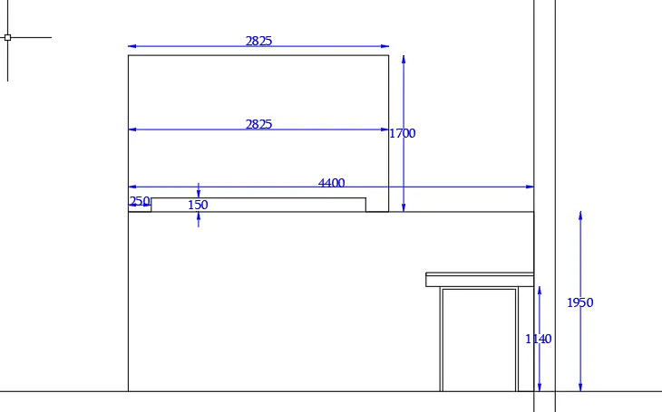
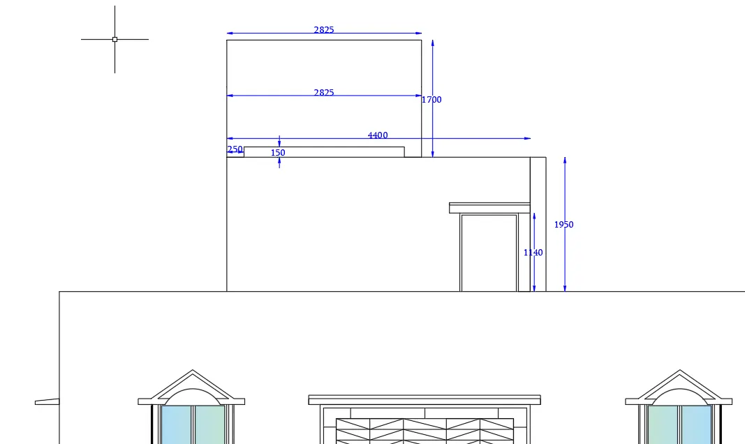
Next we draw the rectangle at the top of the building.
And again we draw the another rectangle on the previous rectangle with the lengths given in the given drawing.
Next we draw the three rectangles at the bottom of the rectangle with the different dimensions.
Step:-2
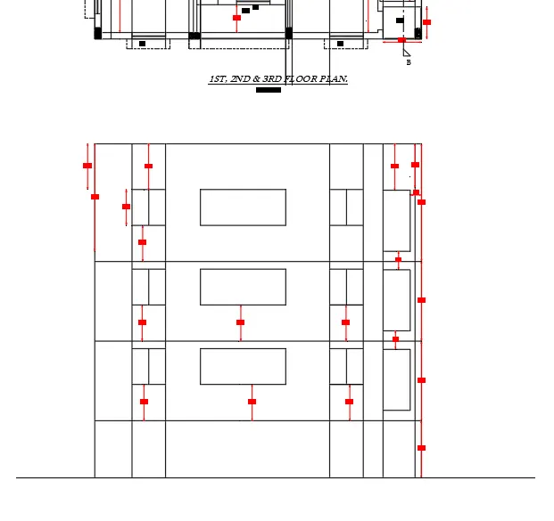
Next we need to draw the sunshades provided in the drawing USING X-LINE command from the floor plan..
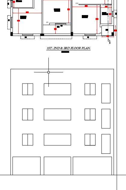
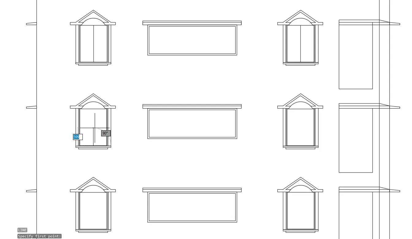
Next we draw the windows with standard construction dimensions with the help of line command and arc command.
Next draw the balcony part using the line command, offset command and trim command.
Next we draw the remaining architectural elements using the line command, rectangle command and offset command.
Next we need to use the single text command to enter the text downside the elevation.
Step:-3
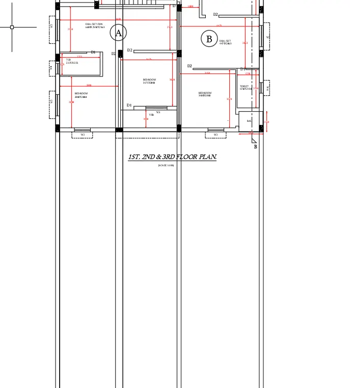
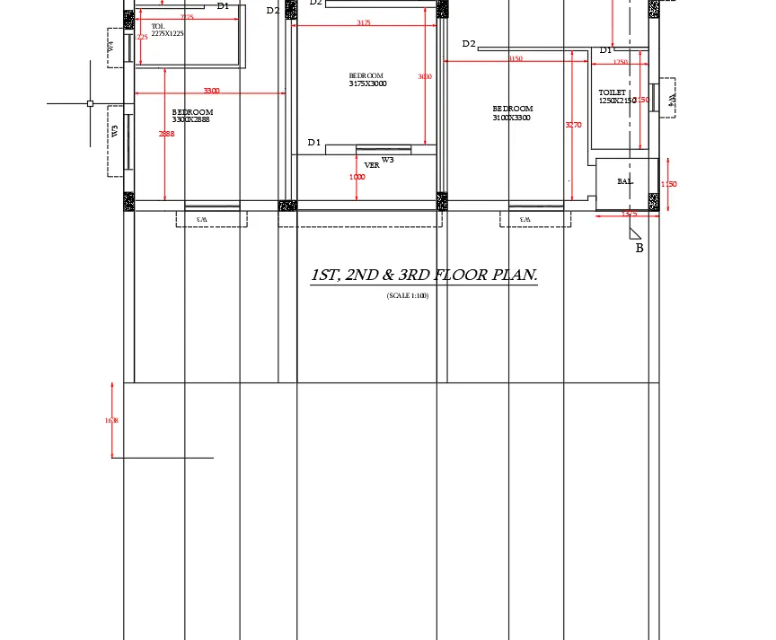
Finally we use the hatch command to hatch the walls, doors, windows and other architectural elements, as shown in the below figure.
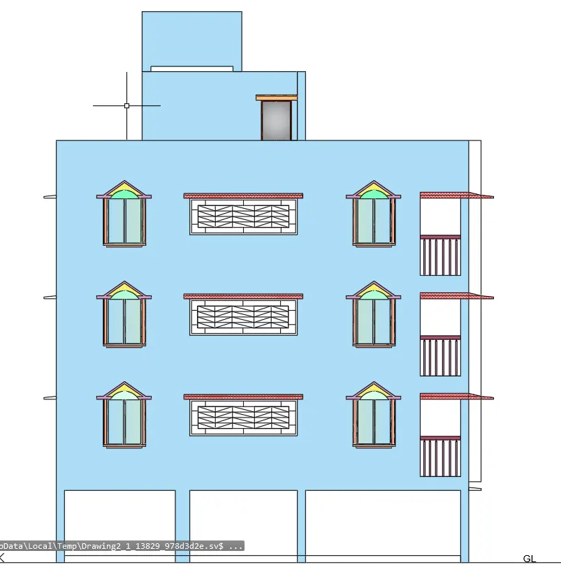
The elevation of the residential building is drawn successfully in the autocad in detail.
And also applied proper hatchs in the walls, doors, windows, and other
AIM:- To create the section view of an industrial building.
And need to provide appropriate hatches and fimensions where ever required.
INTRODUCTION:-
In reference to architectural drawing, the term section typically describes a cut through the body of a building, perpendicular to the horizon line.
A section drawing is one that shows a vertical cut transecting, typically along a primary axis, an object or building.
A section diagram is a view of the building that slices through the building to better see the specific aspects of the building better.
COMMANDS USED:-
Limits command
X-Line command
Line command
Offset command
Hatch command
Dimlinear command
Dimstyle command
Units command
Extend command
Fillet command
Trim command
Join command
Line weight command
Line type command
Object snap command
Rectangle command
Zoom command
PROCEDURE:-
Step:-1
First we have to draw the X-line at anoy point on the screen.
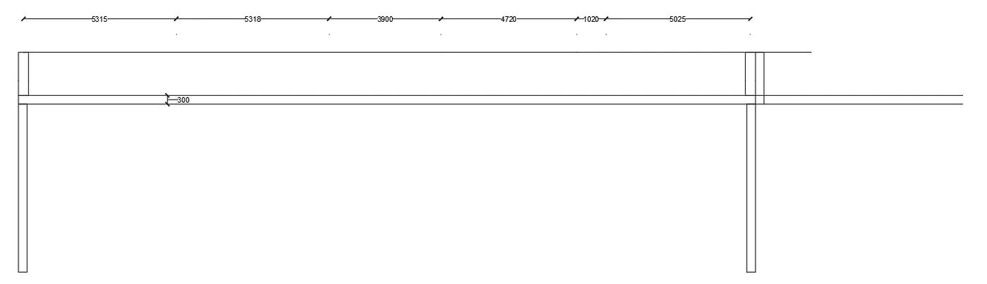
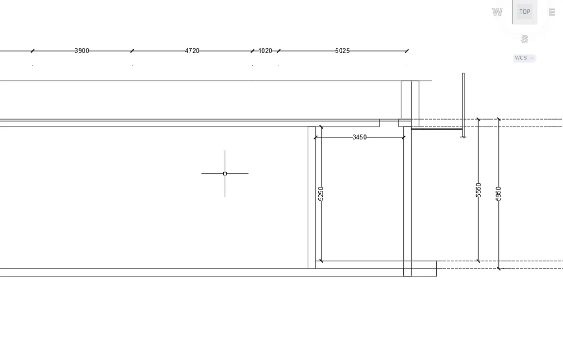
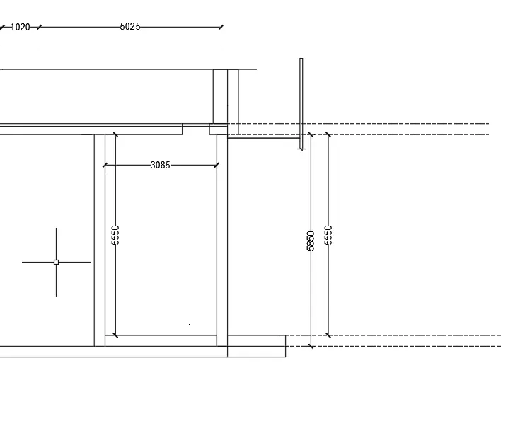
Next offset the line to top to a distance of 5850mm and we have to do offset of last offset line to the distance of 300mm to the top.
Next we have to draw the vertical X-line on any point on the horizontal line.
Next do offset of line to right to a distance of 10635mm
Next offset the last line with a distance of 3900mm to the right.
Next offset the lst line with the distance of 5740mm to the right side.
Next we do the offset for last line with the distance of 5025 to the right side.
Offset the left and right edges with the distance of 400mm.
Next we have to trim the outer edges using the trim command.
Next offset the bottom edge of the top floor to a distance of 25mm.
Next offset the last line with a distance of 75 mm to the bottom.
Next offset the last line with the distance of 100mm to the bottom.
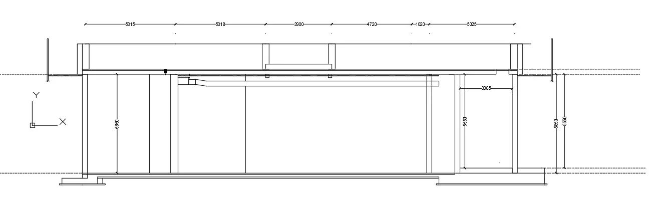
Next we draw the splinkler pipe along with the duct pipe.
The duct pipe thickness is 300mm and the thickness of splinkler pipe is 100mm.
Next we draw the manhole cover with the thickness of 750mm at the right top edge of filter feed walls as shown in the figure.
Next we draw the thickness of pump room slab with the different layers using the line command.
Step:-2
Next we need to use the single text command to enter the text where ever required in the section view of industrial drawing.
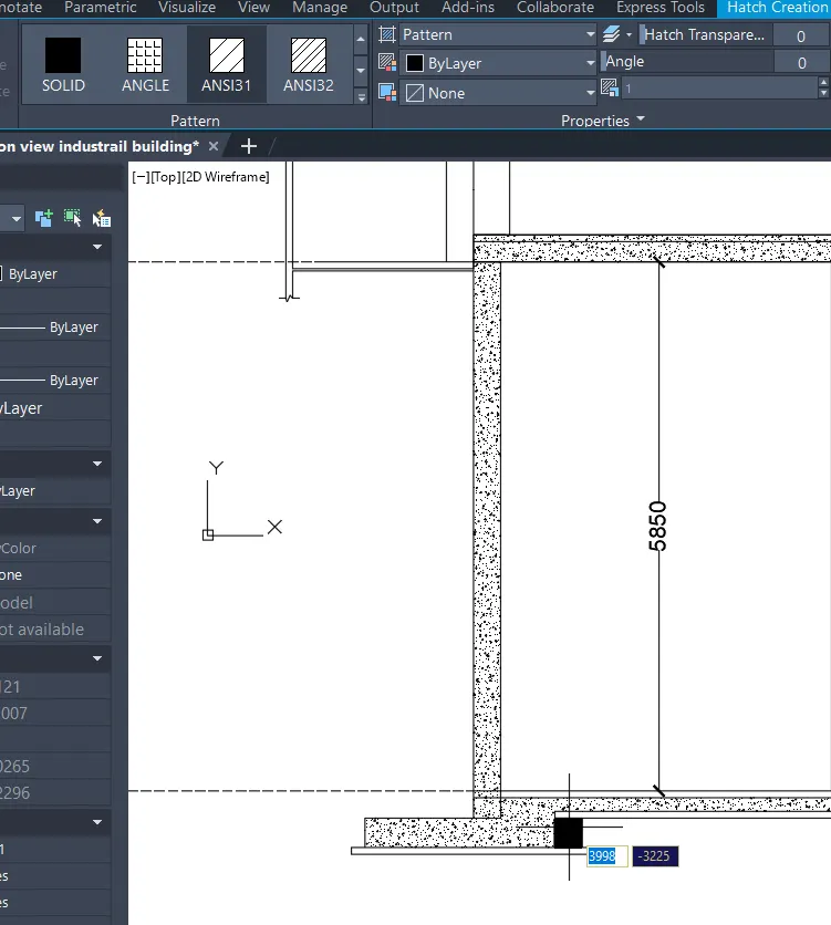
Finally we use the hatch command to hatch the walls and floor slabs as drawn in the below figure.
Finally we have use the dimlinear command to put the dimensions whereever required in the drawing.
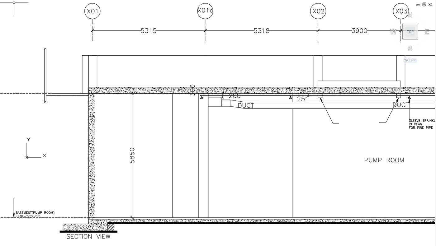
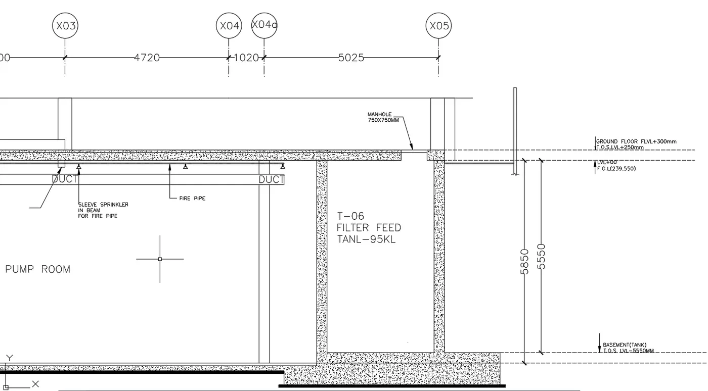
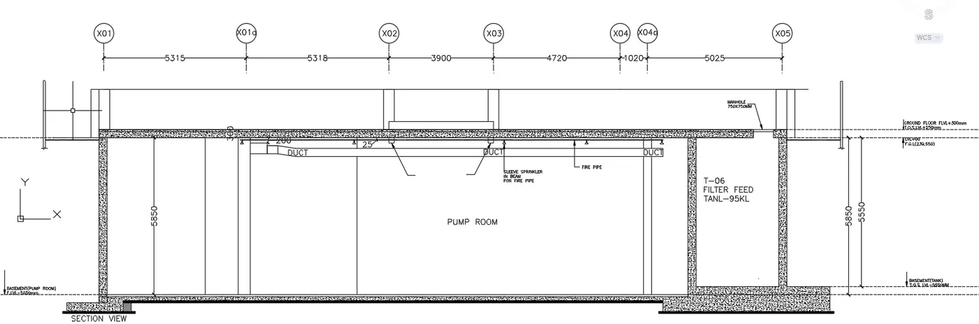
The sectional view of the industrial building is drawn successfully in the autocad in detail.