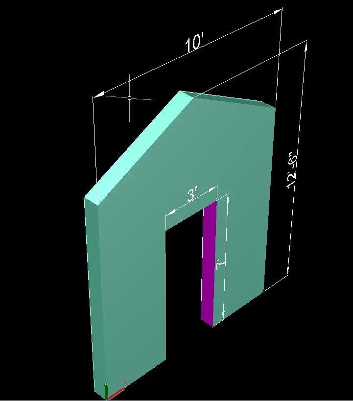
Creating various 3D Models in AutoCad.
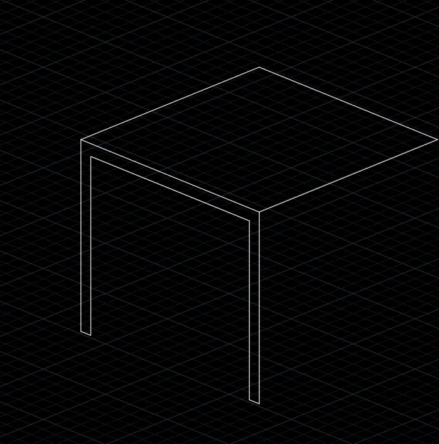
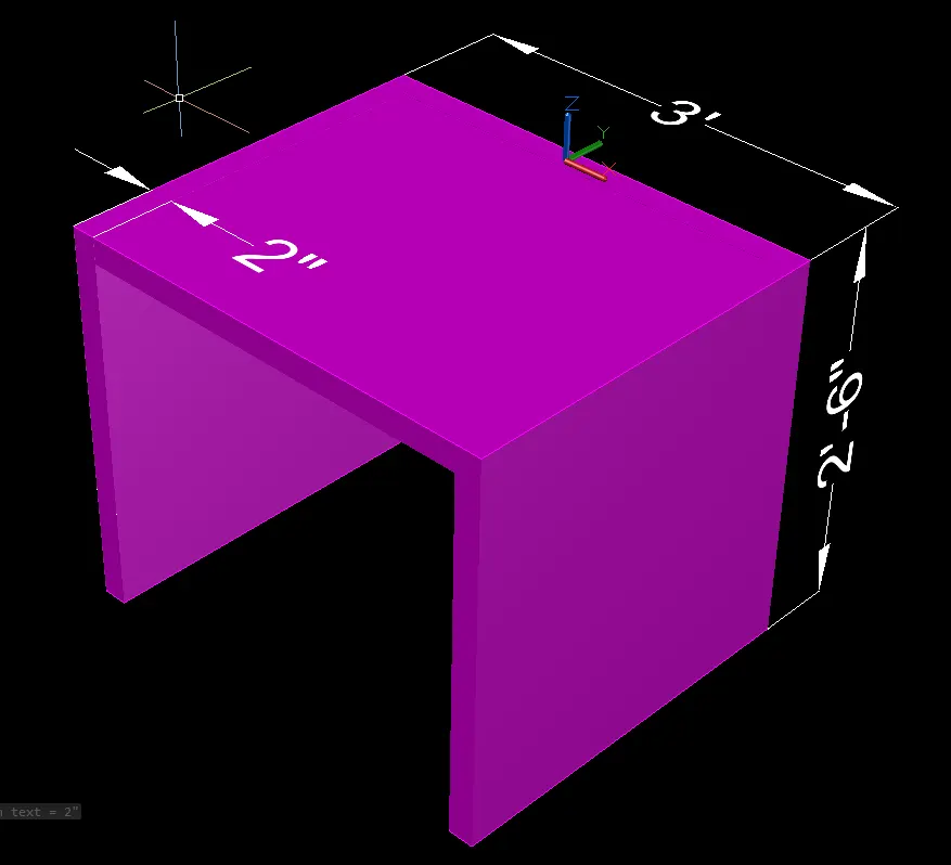
1.Create a 3D Furniture element as shown in the Figure. Assume dimensions which are missing.
AIM: To create a 3D Furniture element as shown in the Figure.
PROCEDURE
- Open AutoCAD and click the workspace icon
- Enter Units and limits
- Line command is used to draw the 3D object
- Command-line draw 2'6" in the Z direction
- Line of 3' in the Y direction
- Line 2' in a negative Z direction
- Offset 2" as the thickness of the 3D object
- Assume the width of the object as 2'3"
- Move USC and face in the desired manner
- Use face command place the particular face and show dimensions
Result:
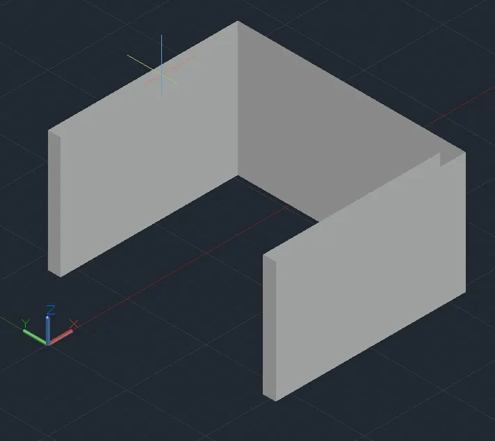
- The 3D furniture element is created in AutoCAD software by using above mentioned procedure as shown below.
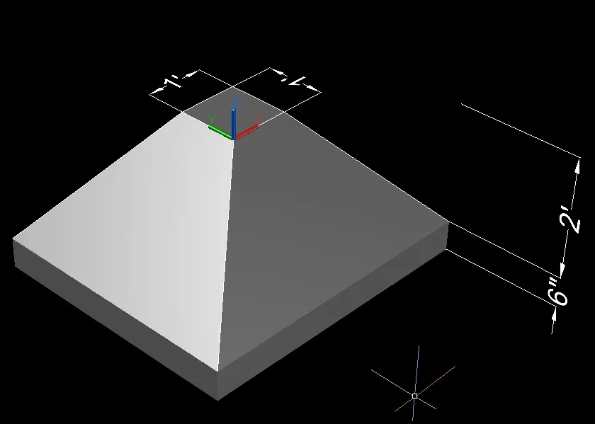
2.Create the 3d Model of an Isolated footing as shown in Figure.
AIM: To create the 3d Model of an Isolated footing as shown in Figure.
PROCEDURE
- Open AutoCAD and click the workspace icon
- Enter Units and limits
- Line command is used to draw the 3D object
- Draw a rectangle (1',1') in the 3D view
- Give offset of 1' to the rectangle on the outside of the rectangle
- Extrude the bigger rectangle to the height of 6"
- Move the inner rectangle at the height of 2'6"
- Join all corners points
- Use the command 3D orbit to move the object in the degree manner and join all the corner points
Result:
3D modal of isolated footing is created in AutoCAD software by following the above mentioned command as shown below.
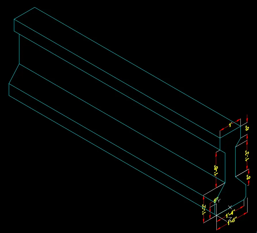
3.Create 3d view of AASTHO typer grider as shown in figure assume dimensions are missing.
AIM- CREATE THE 3D VIEW OF THE AASTHO TYPE GIRDER SHOWN IN THE FIGURE.
PROCEDURE:
Select 3D modeling workspace
select UN command < select engineering< precision>select top plane
select line command
drag cursorx-axis
drag cursor -ve y-axis
drag cursor y-axis< distance>
drag drag cursor x-axis
drag the cursor -ve y-axis< distance>
mirror command use to mirror the lines
sketch rest line.
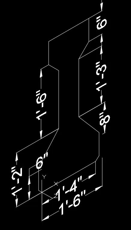
- Select Exturde Command.
Result:-
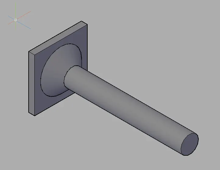
4. Create a 3D Model of a drop column with the panel as shown in section and isometric view. Assume dimensions that are missing.
AIM- CREATE THE 3D MODEL OF A DROP COLUMN WITH A PANEL AS SHOWN IN THE FIGURE.
Procedure:
- select drafting and annotation workspace
- select UN command < select engineering< precision>select rectangle command
- select 3D modeling workspace
- select 3DR command< select object <select rotation axis
select extrude command<select rectangle as object 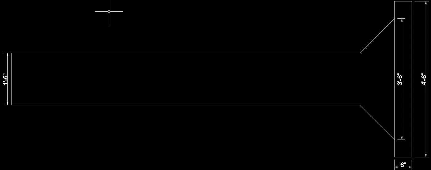
- select ucs icon <select face <select back side
- select circle command< smaller>
- select boundary command<select region option<select circles as object
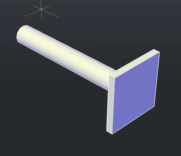
Result:-
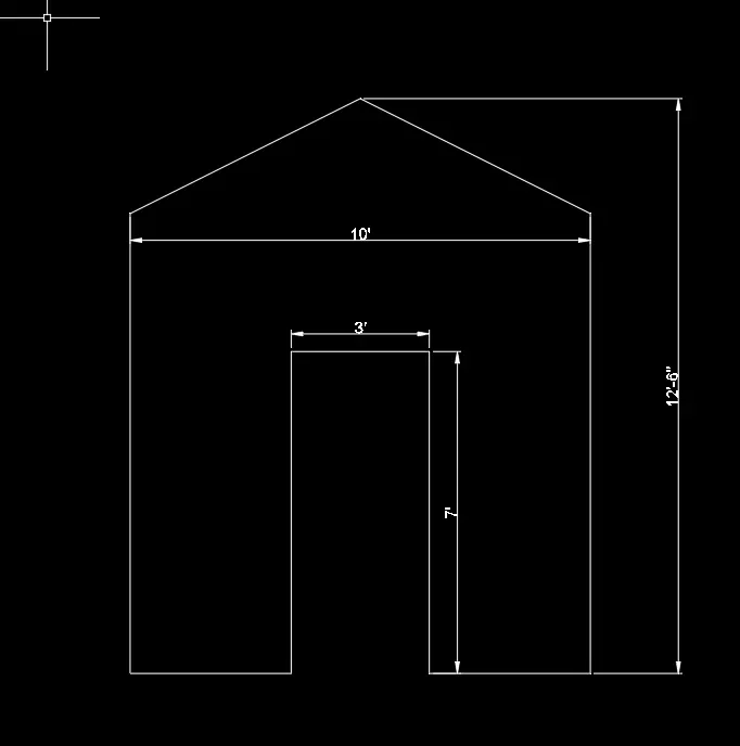
5.Create a 3D Model of a wall as shown in the section. Assume dimensions that are missing.
AIM- CREATE THE 3D MODEL OF A WALL AS SHOWN IN THE FIGURE. CONSIDER WALL THICKNESS AS 9".
PROCEDURE:
- select drafting and annotation workspace
- select UN command < select engineering< precision xss=removed>select line command
- again line command<select midpoint of first-line as the first point
select first line - select line command<select first point
again select second point < join> - trim the rest of unwanted lines
- select offset command< select the second line as object
select offset command<select the second line as object select line command - select unwanted lines
- again line command<select midpoint of first-line as the first point
- select 3D modeling workspace
- select 3df command<select closed object
select 3dr command
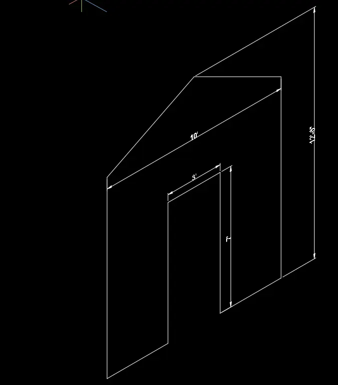
- select extrude command<select wall as object
Result:-