Centrifugal pump design and analysis
Aim: Centrifugal Pump Design and Analysis.
Objective :
- A model Centrifugal Pump and Perform flow simulation Analysis.
- Obtain the relationship between pressure ratio and mass flow rate.
Introduction:
centrifugal pumps are used to transport the fluid. A centrifugal pump is a mechanical device designed to move fluid by means of transfer of rotational energy by one or more driven motors called impellers. Centrifugal Pumps are used to transport fluids by the conversion of rotational kinetic energy to the hydrodynamic energy of the fluid flow. Fluid enters the rapidly rotating impeller along its axis and is cast out by centrifugal force along its circumference through the impeller's vane tips.
The actions of impellers increase the fluid velocity and pressure and also direct towards the pump outlet. The pump casing is specially designed to constrict the fluid from the pump inlet and, direct it into the impeller and then slow and control the fluid before discharge.
Components Of Centrifugal Pump
1) Impeller
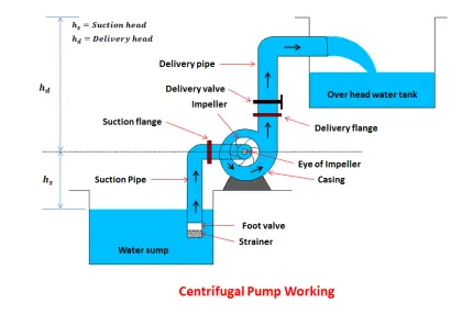
It is a wheel or rotor which is provided with a series of backward curved blades or vanes. It is mounted on a shaft that is coupled to an external source of energy. which imparts the liquid energy to the impeller there making it rotate.
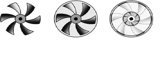
Impeller Are divided into Three Types
a. Open Impeller.
b. Semi-enclosed Impeller.
c. Enclosed Impeller.
2) Casing
It is a pipe that connected the Upper end of the inlet to the pump to the center of the impeller which is commonly known as an Eye. The casing of the centrifugal pump is an airtight passage surrounding the impeller and is designed in such a way that the Kinetic energy of water discharged at the outlet of the impeller is converted into pressure energy before leaves the casing. It is a spiral type in which the area of flow increases gradually.
Commonly three types of casing are used in centrifugal pump
a. Volute casing
b. Vortex Casing
c. Casing with guide blades.
3) Delivery pipe
It is a pipe that is connected at its lower end to the outlet of the pump and it delivers the liquid to the required height. Near the outlet of the pump on the delivery pipe, a valve is provided which controls the flow from the pump into the delivery pipe.
4) Suction Pipe with Foot valve & Strainer
The suction pipe is connected with the inlet of the impeller and the other end is dipped into the sump of water. At the water end, it consists of foot value and strainer. The foot valve is a one-way valve that opens in the upward direction. The strainer is used to filter the unwanted particles present in the water to prevent the centrifugal pump from blockage.
Working :
The first step in the operation of a centrifugal pump is priming. Priming is the operation in which the suction pipe casing of the pump and the position of fluid with the liquid which is to be pumped so that all the air from the position of the pump is driven out and no air is left. The necessity of priming a centrifugal pump is due to the fact that the pressure generated at the centrifugal pump impeller is directly proportional to the density of fluid that is in contact with it.
After the pump is primed the delivery valve is still kept closed and the electric motor is started to rotate the impeller. The delivery valve is kept closed in order to reduce the valve is opened the liquid is made to flow in an outward radial direction thereby vanes of the impeller at the outer circumference with high velocity at outer circumference due to centrifugal action vacuum is created.
This causes liquid from the sump to rush through a suction pipe to the eye of the impeller thereby replacing the long discharge from the center circumference of the impeller is utilized in lifting liquid to the required height through the delivery pipe.
Application Of Centrifugal Pump :
- Oil & Energy - Pumping Crude oil, Slurry & mud, used by Refineries & power generation plants.
- Industrial & Fire Protection Industry - Heating & Ventilation, Boiler Feed Applications, air conditioning, Pressure boosting.
- Waste Management & Agriculture - wastewater processing plants, Irrigation.
Terms
Pressure Ratio :
The ratio of Discharged pressure to inlet Pressure is called the Pressure ratio.
Pressure ratio = Inlet Pressure/ Outlet Pressure
Mass Flow Rate :
Mass flow rate is the mass of the substance that is passed through the cross-sectional area per unit of time.
Explanation:
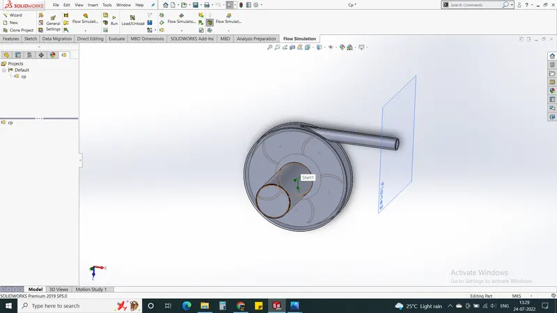
Creation of a model of the Centrifugal Pump as shown below.
Then we have to perform a Flow simulation as per the parameter
i.) To carry out the flow simulation we must make the fig as a controlled volume. Therefore, we use create lid option to close the suction tube and delivery tube.
ii.) Meshing in Solidworks is not that efficient to rotate/ deform the mesh with rotation of the impeller. Therefore, we use the moving reference frame approach to simulate the flow.
Parameters Required :
| S.No. | Parameter | Condition |
| 1 | Project name | Centrifugal Pump |
| 2 | Unit system | MKS or S.I. |
| 3 | Analysis type | internal |
| 4 | Physical feature | Rotation [type – Local region(s) (averaging) |
| 5 | Fluid | Water |
| 6 | Flow type | Laminar & turbulent |
| 7 | Cavitation | No |
iii) Boundry Condition
At Inlet - Environmental Pressure ( P=101325 Pa) & Outlet - Outlet Velocity (v= 10 m/s)
inserting Rotating Region - select it as a reference frame, angular velocity 1000 rad/s
Set iteration - 500 ,uncheck all options under the calculation control option.
iv) Select Goal
Surface goal - surface avg. total pressure
Global Goal - Avg Mass flow rate
v) Run the Simulation
vi) Parametric Study - Create a new Parametric Study
Add boundary condition Velocity - ( Range 10-30m/s with including 5 Steps ) as input simulation parameter.
select Total.Avg Pressure & Mass flow rate as an output parameter.
Result & Explanation :
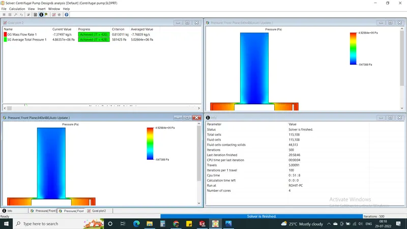
Solver Result :
Total Avg Pressure & Mass flow rate
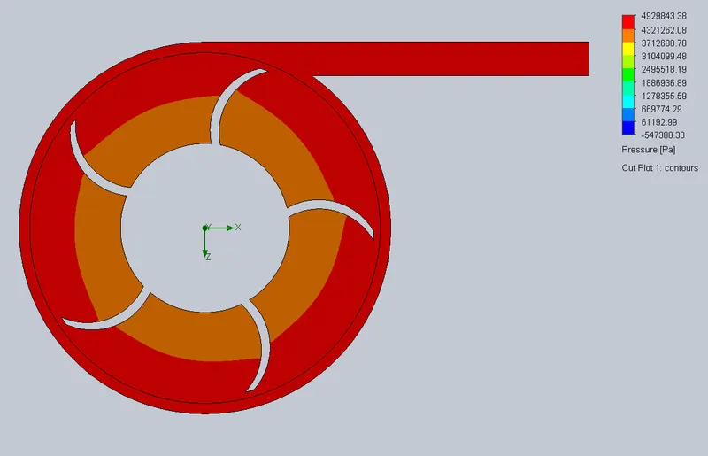
Pressure Plot
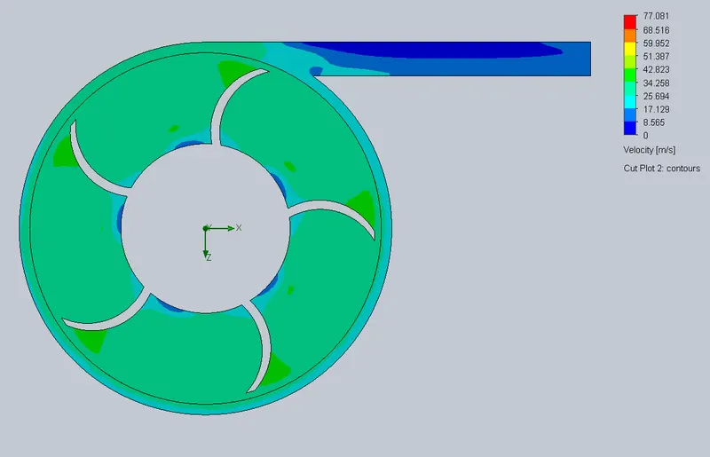
Velocity Plot
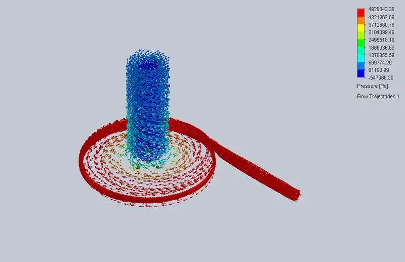
Flow Trajectory
Parametric study

After Performing a Parametric study we got the Result
| Goal (Value) | Design Point 1 | Design Point 2 | Design Point 3 | Design Point 4 | Design Point 5 |
| Environment pressure (Environment Pressure 1) [Pa] | 101325 | 101325 | 101325 | 101325 | 101325 |
| Velocity normal to face (Outlet Velocity 1) [m/s] | 10 | 15 | 20 | 25 | 30 |
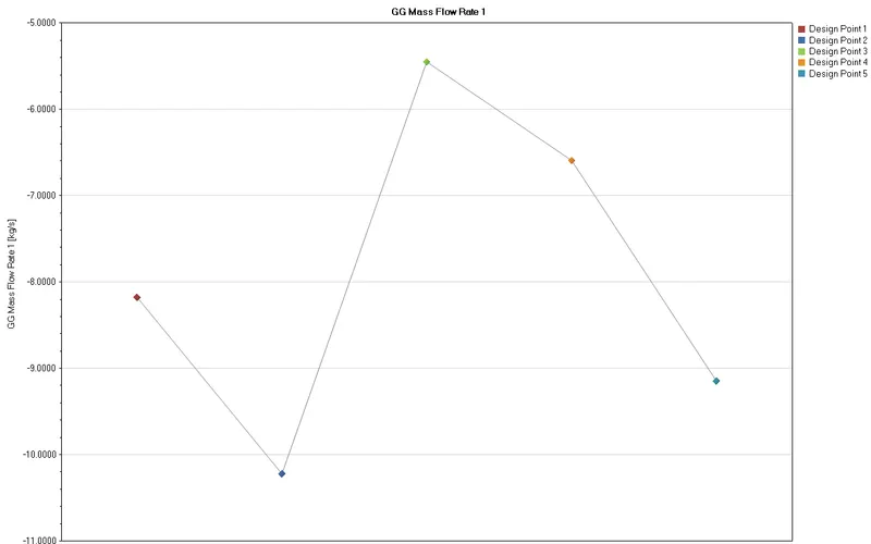
| GG Mass Flow Rate 1 [kg/s] | -8.177094212 | -10.22239588 | -5.449559646 | -6.591227152 | -9.146120315 |
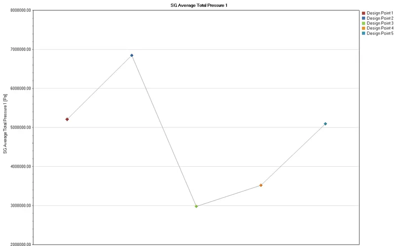
| SG Average Total Pressure 1 [Pa] | 5210959.578 | 6850058.949 | 2979381.286 | 3520235.897 | 5096735.269 |
| Pressure Ratio | 51.42817249 | 67.60482555 | 29.40420712 | 34.74202711 | 50.30086621 |
Avg Mass Flow rate
Avg Total Pressure
Conclusion :
- From Above Simulation we got the result of the Pressure Ratio Vs Mass flow Rate within the Range Of 51.428 - 50.300 & Maximum Pressure ratio we obtained is 67.604. at the lowest mass flow rate -10.22239kg/s.
- So from the above result we can conclude that Pressure & Mass flow rate is inversely Prapotional to each other.
- The maximum total Pressure we obtained from the simulation was 6850058 Pa.