Transient Non linear Dynamic structural analysis for a projectile (mimicking behavior of bird) hitting an aero-engine blade.
OBJECTIVE:
To simulate the virtual scenerio in which, a cylindrical projectile (mimicing a bird) strikes the blade of an aero engine.
During this test, relative velocity is provided to projectile, while the aero engine is considered stationary.
Projectile(Bird) properties:
- Material behaviour = Simple elastic (MAT_001)
- Density = 1 kg/ litre = 1/`10^-6` Kg/`mm^3`
- Strength = 2MPa Youngs Modulus
- Poissons ratio = 0.21
Aero engine Blade properties:
- Material Behaviour = Piecewise Linear plastic (Steel) (MAT_024)
- Density = 7.86 `times``10^-6` Kg/`mm^3`
- Strength = 200 GPa Youngs Modulus
- Poissons ratio = 0.3
Observation:
If blade raptures, then whether it is leaving the casing or not?
The basic idea is that in such scenerio, blade or other associated assembly shouldnot escape the Engine casing
and further damage the fuselage or other part of aeroplane.
In short, the damage must restrict to engine casing only, considering only structural damage.
KINEMATICS USED IN OBSERVATION:
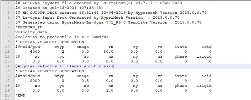
Speed of projectile (bird) = 80 mm/ms i.e 80 Kilometers per second.
Angular velocity of blades = 0.5 rad/s about x axis i.e 500 radians per second. i.e ~4774 revolutions per minute.
NUMBERING SCHEMES IN ANALYSIS:
Range of FEA entities used in Keywoerd file is reprented in table.
| FEA Entity | FROM | TO | Count |
| Nodes | 100000 | 114421 | 14422 |
| Element Shell | 500000 | 509850 | 9851 |
| Element Solid | 519702 | 540545 | 20844 |
| PART | 1000 | 4000 | 4 |
| Material | 100001 | 200001 | 4 |
| Section | 10001 | 40001 | 4 |
| Curves | 20000 | 20000 | 1 |
| Node_Set | 10001 | 10003 | 3 |
| Contact | 10000 | 10003 | 4 |
Attachment: Renumber_log
PRACTISE FOLLOWED:
The Various keywords are defined in the saperate keyword files. Main solver file contains only Boundary conditions.
Advantage of this practise:
- So that these standard files can be accessed by any individual.
- Standardisation.
- Easy debugging
Solver file:
Constraints on Engine casing are present, along with Included file paths for other keywords.
PATH OF FILES:
All Keyword files are kept in a Folder named: 00_Bird_strike
File path: C:UsersUsernameDocumentsCAE courseLS DYNA CourseProject0_Bird_strike
KEYWORD FILES:
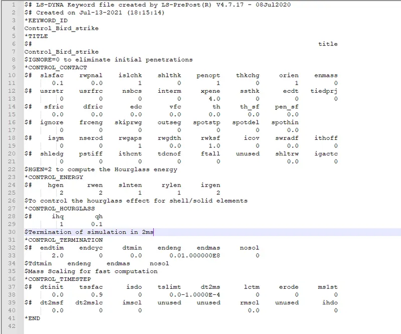
1. Control measures for analysis: (*CONTROL)
Name of Folder: 00_Control
Keywords file name: Control_Card.key
File path: C:UsersUsernameDocumentsCAE courseLS DYNA CourseProject0_Bird_strike0_ControlControl_Card.key
Following is the Keyword file containing *Control_ keywords:
Read comments to undestand the functionality and reason for using the Keyword.
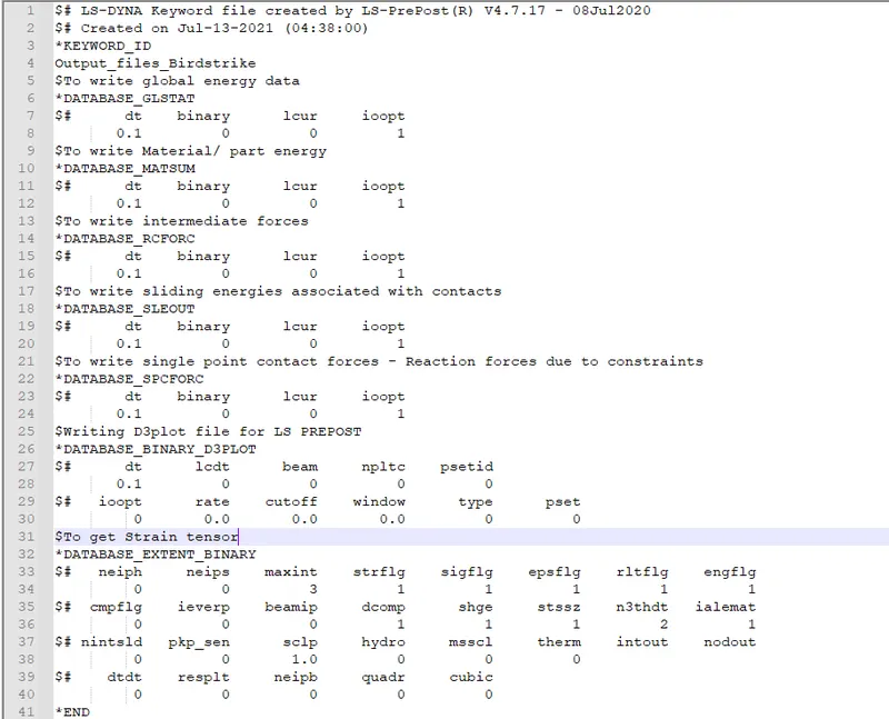
2. Output files written: (*DATABASE)
Name of Folder: 01_Database
Keywords file name: Output_files.key
File path: C:UsersUsernameDocumentsCAE courseLS DYNA CourseProject0_Bird_strike1_DatabaseOutput_files.key
Following is the Keyword file containing *Database_ keywords:
Read comments to undestand the functionality and reason for using the Keyword.
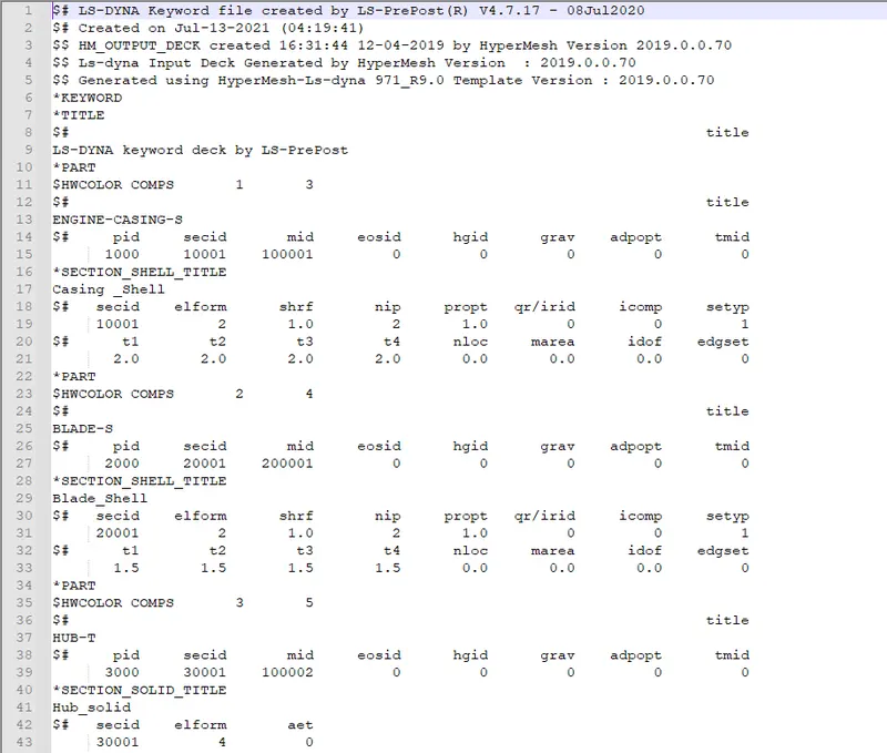
3. Section and part data: (*SECTION/ *PART)
Name of Folder: 02_PartIDs
Keywords file name: PartID.key
File path: C:UsersUsernameDocumentsCAE courseLS DYNA CourseProject0_Bird_strike2_PartIDsPartID.key
Following is the Keyword file containing *Part_ & *Section_ keywords:
Read comments to undestand the functionality and reason for using the Keyword.
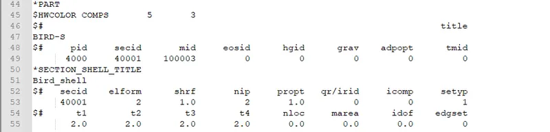
Other than this data for elements (Solid/shell), and nodes is also specified.
4. Data for Material: (*MAT)
Name of Folder: 03_Material
Keywords file name: Materials.key
File path: C:UsersUsernameDocumentsCAE courseLS DYNA CourseProject0_Bird_strike3_MaterialMaterials.key
Following is the Keyword file containing *MAT_ keywords:
Read comments to undestand the functionality and reason for using the Keyword.
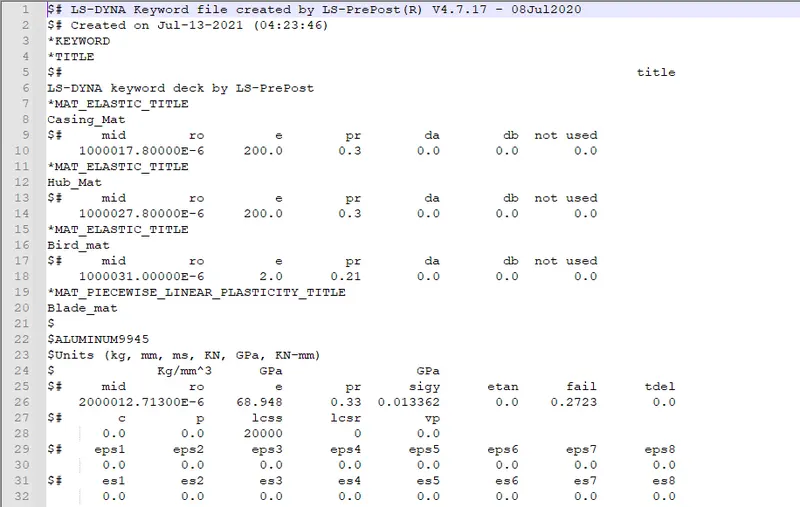
Materials are defined for Casing (MAT_001), Hub(MAY_001), Projectile(MAT_001) and Blades(MAT_024)
Piecewise linear plasticity material is defined using *Define_curve to specify its plastic region.
MAT_001 - MAT_ELSTIC
MAT_024 - MAT_PIECEWISE_LINEAR_PLASTICITY_TITLE
5. Loading on the model: (*INITIAL)
Name of Folder: 06_Loads
Keywords file name: Newvel2.key
File path: C:UsersUsernameDocumentsCAE courseLS DYNA CourseProject0_Bird_strike6_LoadsNewvel2.key
Following is the Keyword file containing *MAT_ keywords:
Read comments to undestand the functionality and reason for using the Keyword.
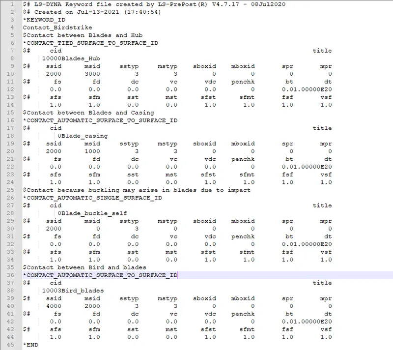
6. Contact data: (*CONTACT)
Name of Folder: 07_Contacts
Keywords file name: Contact.key
File path: C:UsersUsernameDocumentsCAE courseLS DYNA CourseProject0_Bird_strike7_ContactsContact.key
Following is the Keyword file containing *CONTACT_ keywords:
Read comments to undestand the functionality and reason for using the Keyword.
7. Main solver file: (*INCLUDE)
Name of Folder: 08_Solverfile
Keywords file name: Solver.key
File path: C:UsersUsernameDocumentsCAE courseLS DYNA CourseProject0_Bird_strike8_SolverfileSolver.key
Following is the Keyword file containing *CONTACT_ keywords:
Read comments to undestand the functionality and reason for using the Keyword.
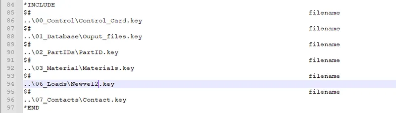
Other than *INCLUDE data, spc constraints are defined for Casing in which lateral deformation is allowed to absorb the shooting parts but longitudonal deformations are constrained as speedy aircraft willnot face forces paralled to its motion due to internal catastrophe.
POST PROCESSING:
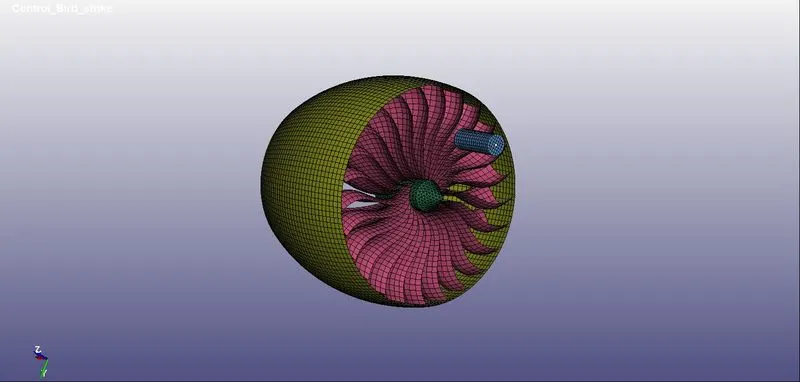
This is the hypothetical mesh to mimic the bird strike.
Folder Tree:
*INCLUDE_PATH: C:UsersUsernameDocumentsCAE courseLS DYNA CourseProject
00_Bird_Strike
>00_Control
>Control_Card.key
>01_Database
>Ouput_files.key
>02_PartIDs
>PartID.key
>03_Material
>Materials.key
>06_Loads
>Newvel2.key
>07_Contacts
>Contact.key
>08_Solverfile
>Solver.key
OBSERVATIONS FROM ANALYSIS:
Are deformations elastic or plastic?
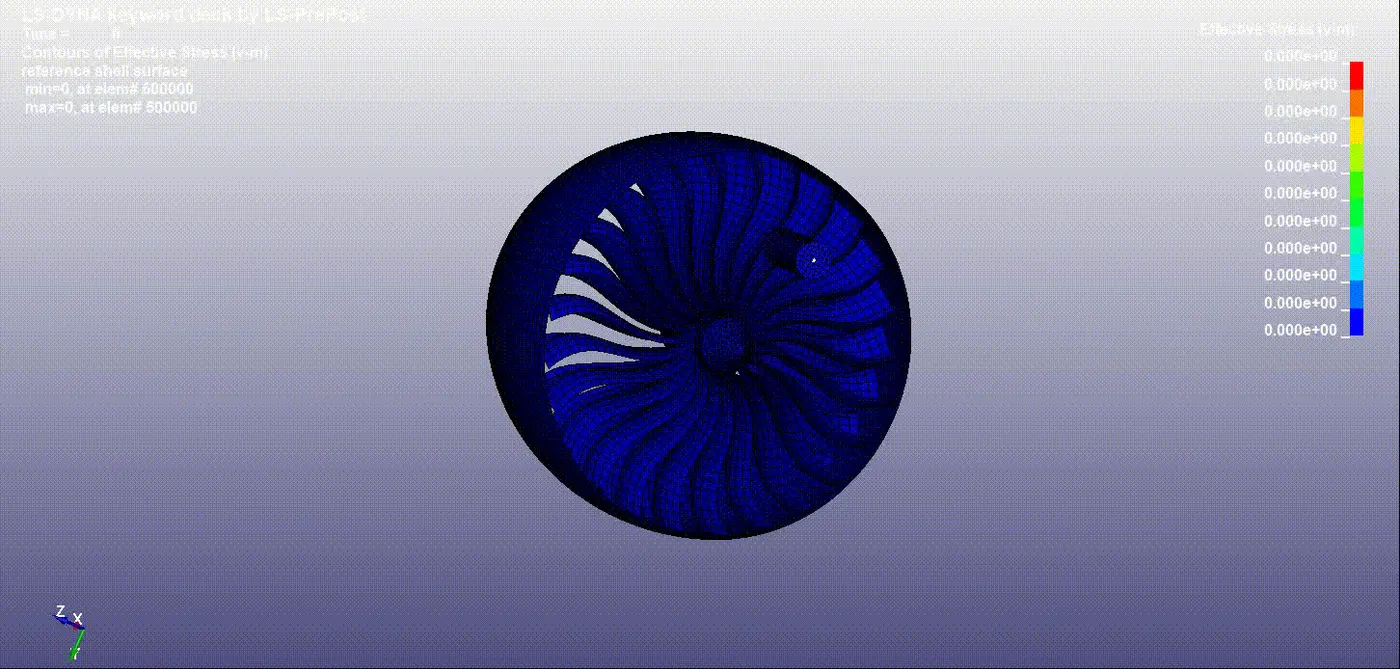
Effective stress with time for Blade elements:
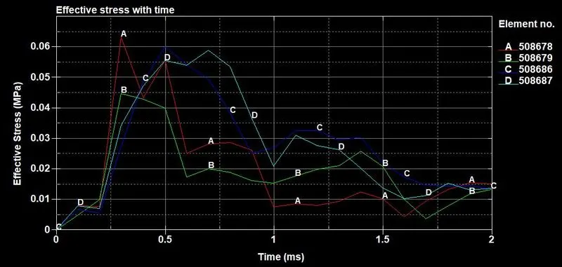
Peak Stress values:
Peak stresses emerge between 0 to 1 ms.
Considering at time, t = 0.3ms
Element IDs: 508678, 508679, 508686, 508687
| Element ID | Effective stress (MPa) |
| 508678 | 0.0633 |
| 508679 | 0.0449 |
| 508686 | 0.0343 |
| 508687 | 0.0273 |
Average effective stress: (0.0633 + 0.0449 + 0.0343 + 0.0273)/4 = 0.04245 MPa
Yielding for the blade material starts from 0.0133 MPa
So effective stress exceeds the Yield hence, all deformations are plastic.
Are strains large enough to create rupture?
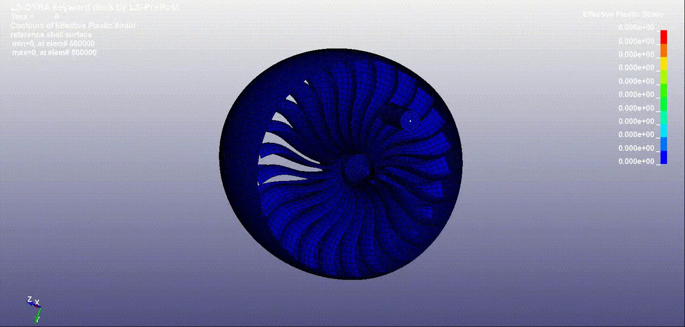
Effective plastic strains with time
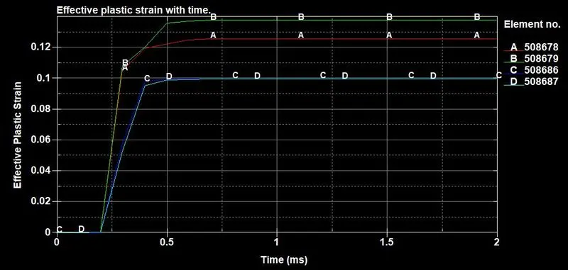
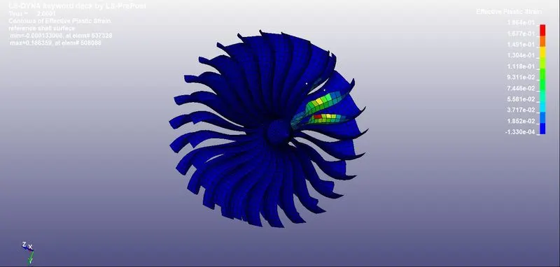
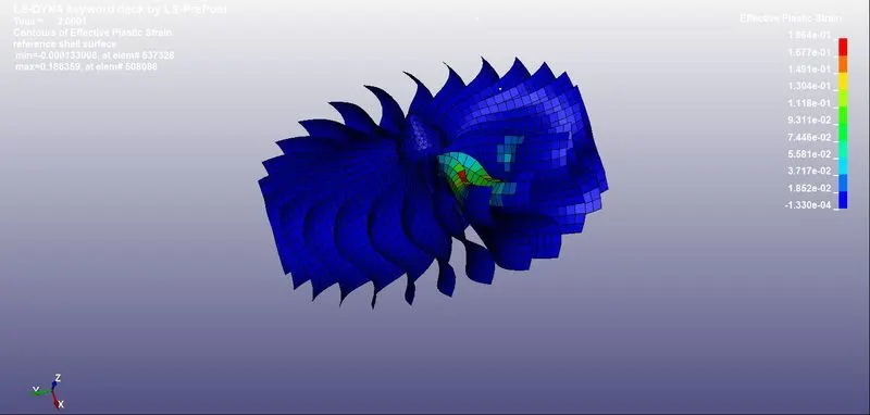
Maximum effective plastic strain is close to 0.13 ie 13% strain
However, fracture for blade material happens at 27% strains.
Since, strains are lesser than fracture strain or ultimate strain
Strain range for elems:
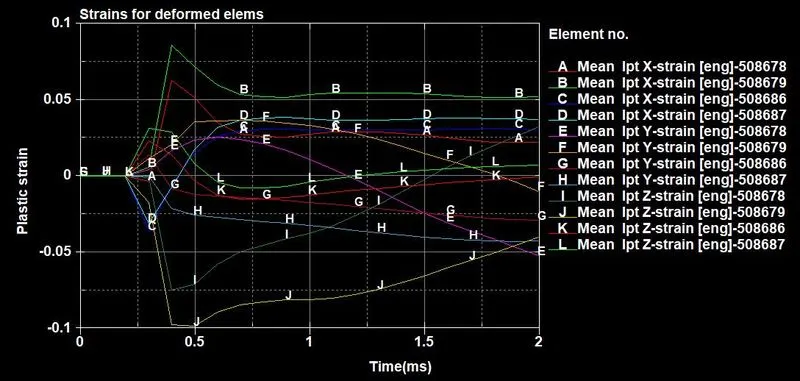
Fracture window is from 0.27 to -0.27 i.e 27% strain window.
SIMULATION VIDEO:
Simulation showing Effective stress
Simulation showing Effective strain
Physical Deformation to compare with tests:
DEBUGGING DURING SIMULATION:
Problems encountered -
- Errors associated with inclusion files.
- Minimum timestep.
- No proper rotation of blades.
Actions taken -
- Checked the addressing of files in *INCLUDE file.
- Reduced the termination time.
- Velocity card using *INITIAL_VELOCITY_GENERATION, earlier velocity was assigned by defining a node set and *PRESCRIBED_MOTION_SET card.