Aston Martin ONE-77 Challenge-11 (Project)
SURFACE MODELLING OF AN ASTON MARTIN CAR USING SOLIDWORKS
SURESHKUMAR
INTRODUCTION
Aston Martin Lagonda is a British independent manufacturer of luxury sports and grand tourers. It was founded in 1913 by Lionel martin and Robert Bamford. Steered from 1947 by David brown, it became associated with expensive grand touring cars in the 1950s and 1960s, and with the fictional character James bond following his use of a DB5 model in the 1964 film Goldfinger. Their sports cars are regarded as a British cultural icon. Aston Martin has held a royal warrant as purveyor of motorcars to the Prince of Wales since 1982, and has over 160 car dealerships in 53 countries, making it a global automobile brand. The company is traded at the London stock exchange and is a constituent of the FTSE 250 index. In 2003 it received the queen’s award of enterprise for outstanding contribution to international trade. The company has survived seven bankruptcies throughout its history. The headquarters and main production of its sports cars and grand tourers are in a 55-acre facility in Gaydon, Warwickshire, England on the former site of RAF Gaydon.
Martin raced specials at Aston hill near Aston Clinton, and the pair decided to make their own vehicles. The first car to be named Aston Martin was created by Martin by fitting a four-cylinder Coventry-simplex engine to the chassis of a 1908 Isotta Fraschini. They acquired premises at Henniker Mews in Kensington and produced their first car in March 1915. Production could not start because of the outbreak of the first world war, when Martin joined the admiralty and Bamford joined the army service crops. After the war they found new premises at Abingdon Road, Kensington and designed a new car. In 1947, Huddersfield gear and machine tools manufacturer David brown limited bought Aston Martin putting it under control of its Tractor Group. David Brown became Aston Martin's latest saviour. He also acquired without its factory Lagonda’s business for its 2.6-litre W-O Bentley-designed engine.
Lagonda moved operations to Newport Pagnell and shared engines, resources and workshops. Aston Martin began to build the classic "DB" series of cars.
The components which we will learn in this Aston Martin car are:
- Blueprint setup
- Main body
- Door and Mirror
- Front, rear and side windshield
- Lights
- Front and rear bumper
- Hood
- Rim and tire
- Disk and caliper
OBJECTIVE
- To address issues such as carbon footprint, noise pollution, aerodynamics and passenger comfort as well as contributing to national security.
- To build a car that could achieve the maximum speed without vibration and any components failure in run condition. Because it’s a sports edition.
- To improve the speed of car to reach designation with minimum time period.
- To reduce the maintainability though minimize the manual works and replace the mechanical components with sensors.
- To control the operating economy by improving the engine performance, monitoring fuel consumption, reduce the accidents, etc.
- The car design should impress the customers with exciting interior and exterior, comfortable seating, speed, etc.
DESIGN PROCESS
The design process is an approach for breaking down a large project into manageable chunks. architects, engineers, scientists are use the design process to solve a variety of problems. Use this process to define the steps needed to tackle each project, and remember to hold to all of your ideas and sketches throughout the process.

DESIGN APPROACH
There are two types of approach in design procedure. 1. Bottom-up approach and 2. Top-down approach. The difference between this two is the part file, because it’s not necessary to top-down approach. Here in this project, we have used Bottom-up approach and we get the clear idea by defining these terms.
- Top-down approach: In the top-down model, an overview of the system is formulated without going into detail for any part of it. So, you can start your work in the assembly and built parts to fit in the assembly. You can use the geometry of one part to help define the other parts or to create machined features that are added only after the parts are assembled.
- Bottom-up approach: In this design, you can create parts, insert them into an assembly, and constraint them as required by your design. An advantage of bottom-up design is that, since components are designed independently, their relationships and regeneration behaviour are similar than in top-down design.
MODULES IN SOLIDWORKS
Solidworks extends design applications through full integration with best-in-class solution. And each module has different features and working procedures that will help on your design process. The following modules are explained below.
- Part modules
- Assembly modules
- Surface modules
- Sheet metal modules
- Drawing
- PhotoWorks
Part modelling:
This module produces parts easily and rapidly by creating features such as extrude, revolve, lofts, sweeps, patterns, etc. in solidworks, you can design a part by sketching its components shapes and defining their size, shape and Inter-relationships.
Assembly modelling:
Assembly design gives a user the ability to design with user-controlled associability. Solidworks builds these individual parts and sub-assemblies into an assembly in a hierarchical manner. This is based on relationships defined by the constraints.
Surface modelling:
For designing dies, castings or injections molds, surface modelling capability is important. Solidworks surface module can create complex models from free form shapes. You can create complex surfaces using lofts and sweeps with guide curve, drag-handles for easy control ad innovative surface feature.
Sheet metal design:
Sheet metal parts are generally used as enclosures for components or to provide support to other components. We can design a sheet metal part on its own without any references to the parts it will enclose. The main feature of sheet metal is its ability to be formed and shaped by a number of processes.
Drawing:
A 2D drawing view is a representation of a 3D cad part or assembly that is placed on drawing sheet. The drawing views represent the shape of the object when viewed from various standard directions such as front, side, top and so on.
PhotoWorks:
Photoview 360 is a solidworks add-in that produce photo-realistic rendering of solidworks models. The rendered image incorporates the appearances, lighting, scene and decals included with the model.
DESIGN METHODOLOGY:
Design methodology refers to the development of a system or method for a unique situation. The key to design methodology is finding the best solution for each design situation, whether it be in industrial design, architecture or technology. Design methodology stresses the use of brainstorming to encourage innovative ideas and collaborative thinking to work through each proposed idea and arrive at the best solution. Meeting the needs and wants of the end user is the most critical concern. Design methodology also employs basic research methods, such as analysis and testing.
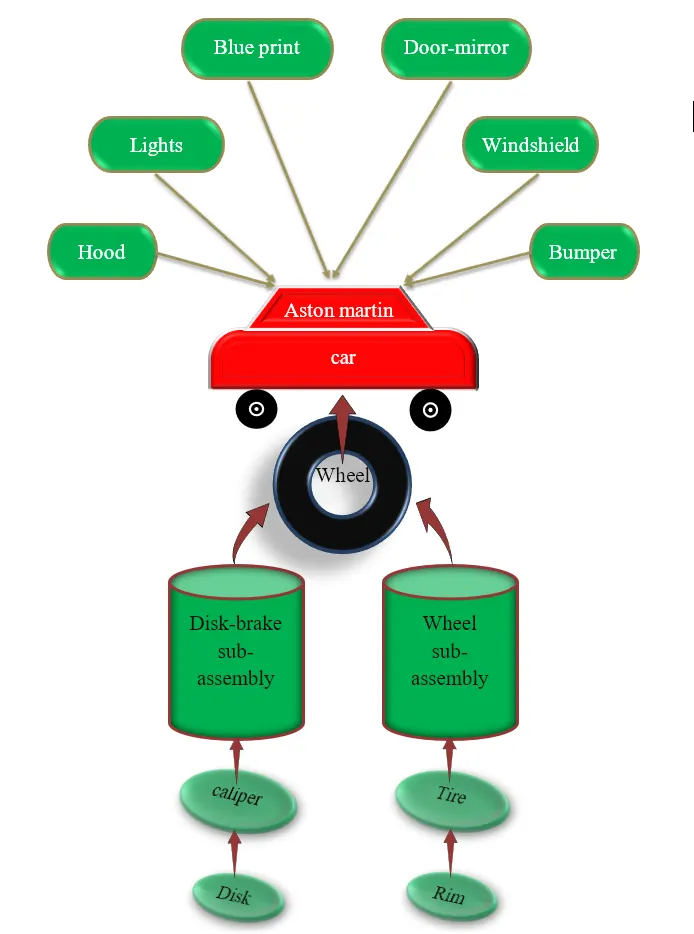
First let’s see what basic sketch entities, features and constraints are in solidworks to create the parts.
SKETCH ENTITIES:
It helps user to create sketch required to feature creation. So, we can use the specific number of sketch entities to create a 2D base sketch for parts development. Also, the sketch tools are available to modify and edit the sketch for required shape.
Line: we can use the line entities to draw a straight line to connect the two points with required constraints along with proper dimensions.
Circle: we can use the circle entities to draw a circle based on center point that may be an origin point, vertex or anything.
Spline: we can use the spline entities to draw a special type of curves and critical shaped curves by connecting two or more points.
Rectangle: it’s closed sketch entities to draw a square as well as rectangles from an origin, vertex, edges, or face center.
Arc: it is a portion of circle to connect the two points by drag the cursor based on center point or starting point.
Offset: add sketch entities by offsetting edges, faces, curves or sketch entities with a specific distance.
Trim: trim or extend the sketch entities used to deletes a sketch entity or a sketch entity to be coincident to another.
Sketch pattern: add sketch entities by linear or circular pattern based on direction and number of instances.
Mirror: we can mirror the selected entities about a center line or center plane.
Move/copy/rotate: we can move, copy, rotate, scale and stretch a sketch entity by defining the direction or base point.
FEATURES:
It helps user to create 3D sketch from 2D sketch by using required features in comment manager. also, we can add or remove the materials from existing part model to satisfy the requirement. Before activate the feature comment we should verify that the 2D sketches are in fully defined sketch with proper dimensions and constraints.
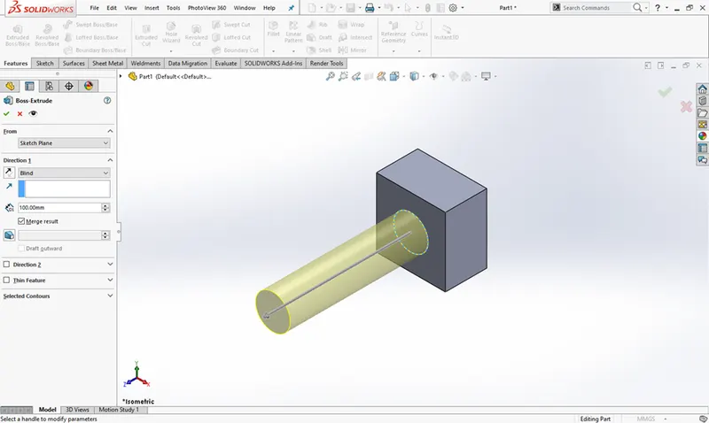
Extrude: we can add or remove the materials by specifying the directions and start point. At the same time user can use draft and thin feature to change the shape of model.
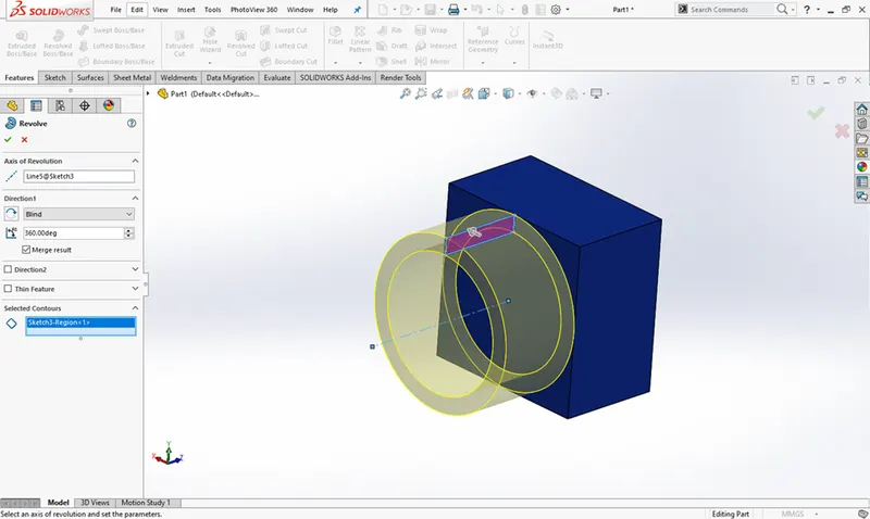
Revolve: it is same as extrude to add or remove the materials while give direction except specifying the axis of revolution to achieve the revolve feature. Thin feature is also here in revolve. And only we can revolve or revolve cut the closed sketch profiles. Open sketch profile cannot use to revolve feature.
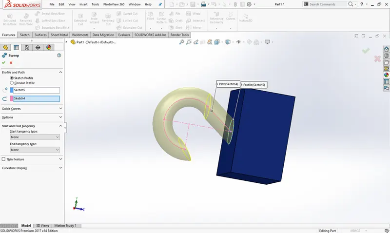
Swept: it is used to sweep a closed sketch profile along an open or closed guide path to create a solid part. We can develop the complex solid model based on guide path which gives the direction to base profile.
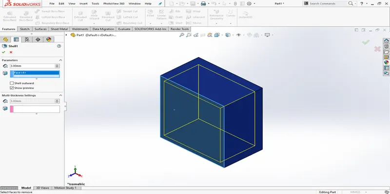
Shell: we can remove the material from a solid body to create a thin-walled feature. In shell feature the selected faces will delete from body otherwise the shell feature lies inside the body if you are not select the any face.
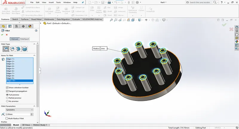
Fillet: it is very useful feature ever in any designing software because to remove the shape edges, increase the smoothness of edges it will help. There are many fillet option such as variable, round, face and constant fillet for our requirement.
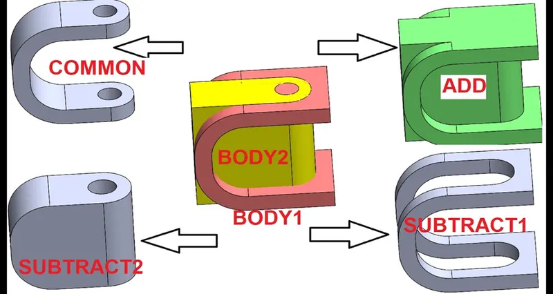
Combine: here we can add or subtract two different bodies which two bodies are in any contact with each other to bring the single part.
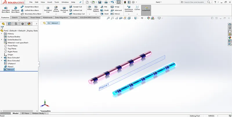
Mirror: mirror is widely using feature to reduce the number of steps need to design a part. With the help of reference plane or face we can mirror the body or other features like fillet.
Pattern: after completely finished part or features we can pattern that by defining the direction and number of instance. It has also similar purpose as mirror to reduce the number of steps. And there are many types of patterns here to perform such as linear, circular, etc.
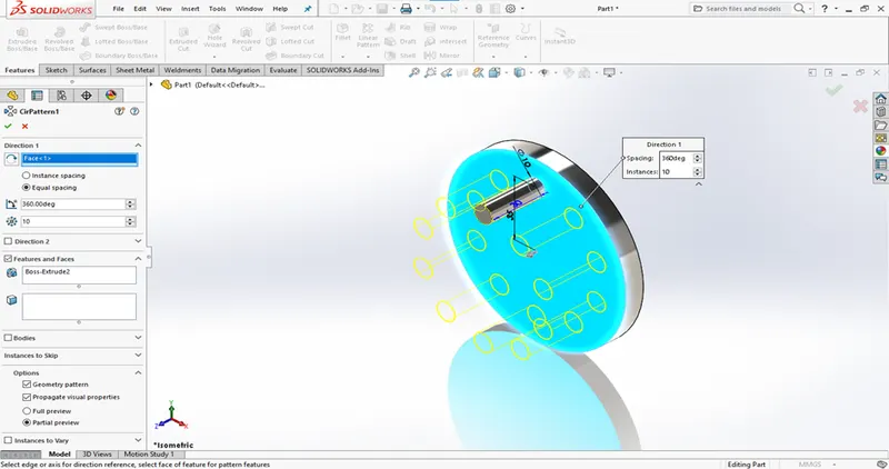
SURFACES:
Surface models are a type of 3D models with no thickness. These models are widely used in industries like automobiles, aerospace, medicals, and so on. In part modelling, you have created models with mass properties but surface models do not have thickness. The surfaces are generally used to create models of complex shapes.
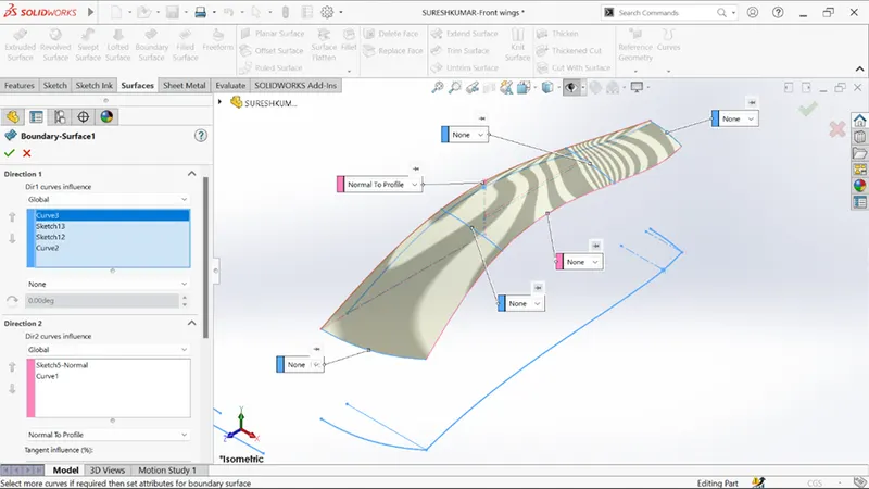
Boundary surface: creates a surface between profiles that can be tangent or curvature in all directions. In the graphics area, use connectors or instant 3D drag handles to shape the boundary surface.
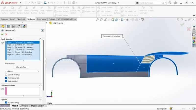
Filled surface: patches a surface within a boundary defined by edges, sketches, or curves. Use constrains curves to fill surfaces and adjust resolution control to improve surface finish.
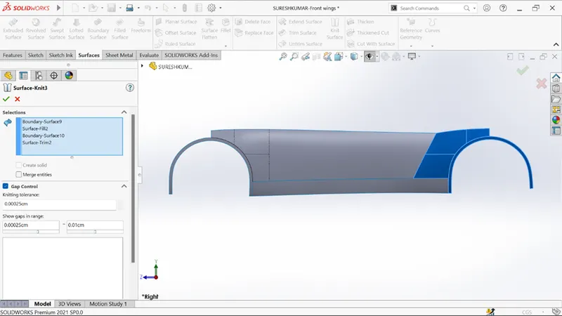
Knit surface: combines two or more adjacent, nonintersecting surfaces into a single surface body. The surface must join at an edge. if the resulting knit surface enclose a volume, you can create a solid body from the property manager.
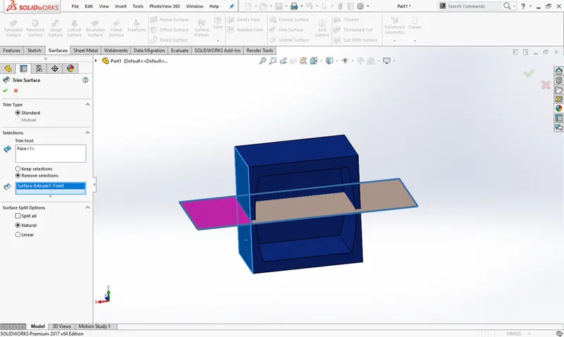
Trim surface: it removes a surface from target body where one surface intersects with another surface, a plane or a sketch. this allows even very difficult part design to be done.
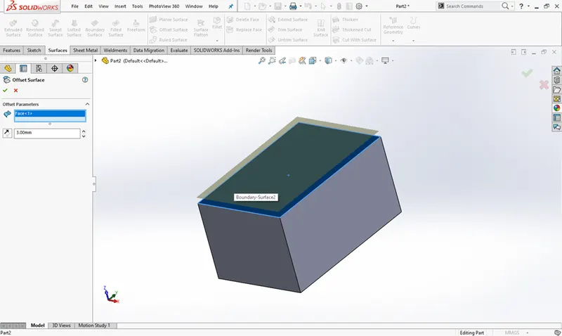
Offset surface: it creates surfaces from one or more continuous surfaces and faces with distance. It may be use in assembly modelling when you use it from base part to design other related parts.
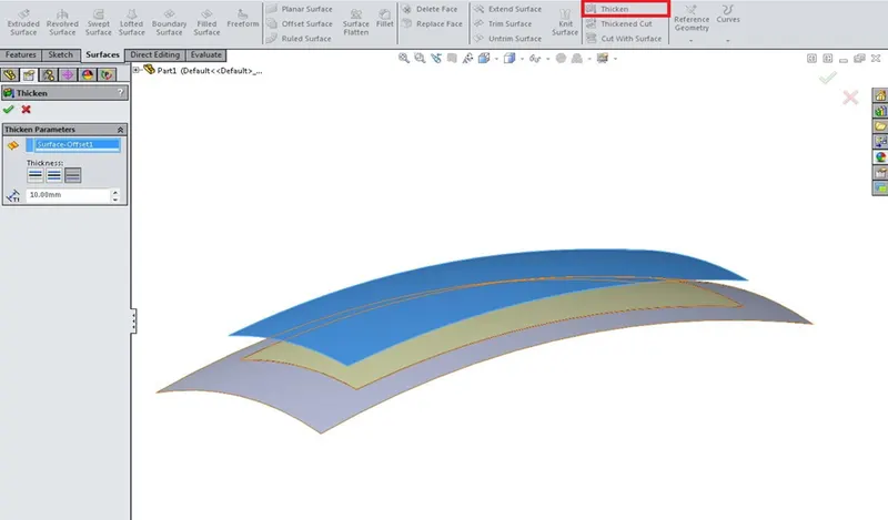
Thicken: to add material on existing part by defining the thickness value with the help of select any faces. Also, there are thickness option for that like mid plane, upward and downward thicken.
Reference geometry:
We can use this feature often to draw the sketch like using this as permanent geometry we can start sketching easily. So, lets me explain that clearly below.
Plane: we can create the extra planes instead of primary planes. But this plane can be formed only from primary planes.
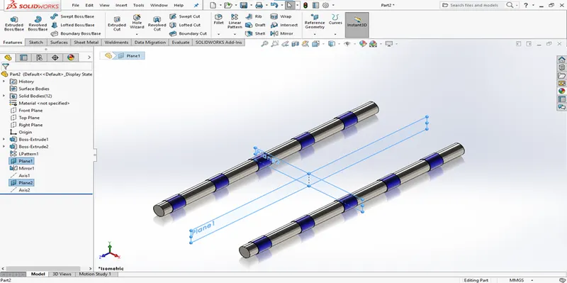
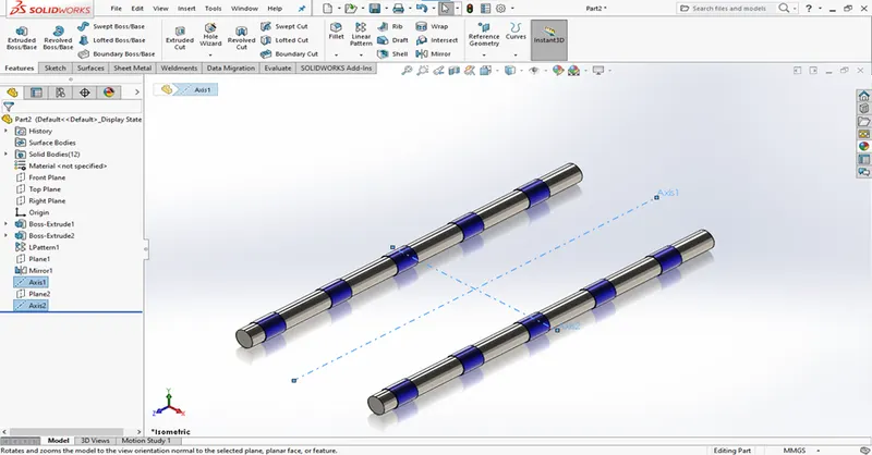
Axis: we can create the axis using planes, vertex, face, etc. this are all mostly use in assembly file to give mate comments.
CURVES:
This feature comments also similar with reference geometry. But it acts as a sketch to move on next feature. So, let’s see this clearly below.
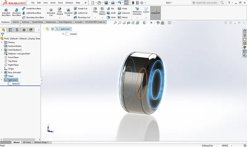
Split line: its only use for split the face or surface by using the sketch entity or blocks are already existing. It is very useful for give the various appearance to the models to improve the graphical look like beautiful.
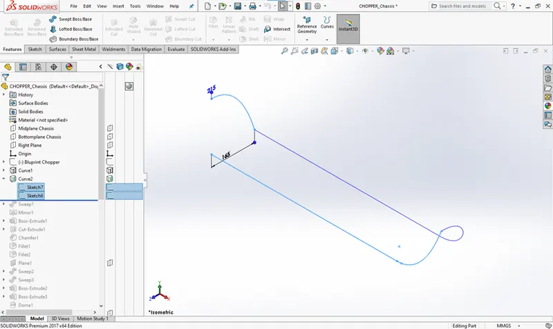
Projected curve: sometime we need to draw the difficult 3D sketch but we don’t idea on it how to create 3D sketch. at the time we can use it to make it easier.
Mate: Mate feature creates geometric relationship between assembly parts. When we add mates, it defines the allowable direction of linear or rotational motion of component within its degree of freedom. Otherwise, the assembly parts are fixed with base part and it will float along with base part. This feature includes as below:
- Coincident mate: it used to mate the two bodies coincident to make a contact with each other. After this mate the one part turns to get only the linear motion based on where we apply this mate like on face, corner or vertex.
- Concentric mate: two circular faces are mate concentric by its axis or circular edges. This mate allows the rotational motion about the axis.
- Distance mate: after selecting the mate references assign the distance to locate the parts.
- Tangent mate: mate two entities tangent to the selected faces, edges, or vertices. you can now create a tangent mate that will connect two parts together by tangent faces or edges. Simply select a face on one part and a face on another.
Now we have completed discussion of how the features work under solid works. Let us see the application of the features in the Aston Martin car that we have built. We are going to discuss part by part as shown in the flowchart. So finally let’s start the Aston Martin car part design procedure and every parts application.
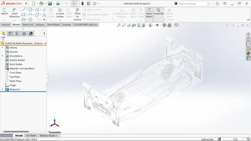
Blueprints: it is basic thing ever in big projects to start off that design. Using primary and reference plane I had completed the blueprint setup. Also, I had used properties and transparency to make its position correctly and clear visibility. Transparency is important thing because during the editing sketch you maybe get confused.
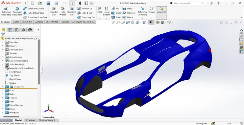
Aston Martin: Now let’s start the design work with the help of blueprints. Here we are going do design the surface model of an Aston Martin so most of the sketch tool and feature is projected curves, knit surface and boundary surface. Projected curves help to start the process. And I just want the half of car body because another half mostly similar to it. So, I had used the mirror command to finish the design. The important thing in surface modelling is sketch entities geometry relations. If you make any error on it, the resultant surface is not come what you expected.
Features used to create the Aston Martin:
- Sketch entities
- Projected curves
- Planes
- Extrude/cut-extrude
- Extruded surface
- Boundary surface
- Filled surface
- Knit surface
- Trim surface
- Ruled surface
- Mirror
- Fillet
- Surface offset
- Thicken
- Combine
- Split line
- Pattern
- Move/copy body
- Delete/keep body
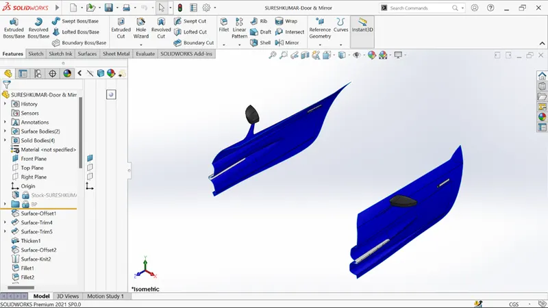
Door and Mirror: it is an individual part in any cars, so I used “split” command to separate it from main body. First time I used part modelling to creates the mirror.
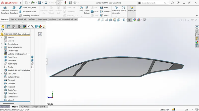
Windshield: i just designed three windshields using same split tool. Here I did not edit more features just mirror it and given appearances.
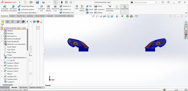
Lights: we are all know how it is important in any fields. I just designed it for requirement in part modelling. Here the designed light is simple but we can develop it for customer expectation. I had designed only front light and for rear light I just given an appearance.
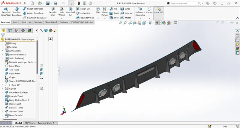
Bumper: Bumpers are located at the very front of the vehicle, rear bottom of the vehicle. They're intended to be the first thing to hit an object in front of them (such as another vehicle) and to minimize the impact and damage to the rest of the vehicle, minimizing repair costs. Here I added light and exhaust with it and mirror it.
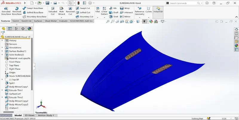
Hood: A car hood, also referred to as a bonnet in some other countries, is the hinged cover that rests over the engine of a front-engine vehicle. Its purpose is to provide access to the engine for repair and maintenance. Here I added a small grill for air ventilation and mirror it.
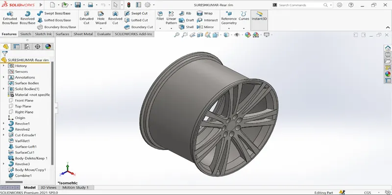
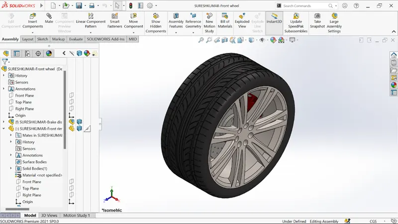
Rim and tire: rims are the outer parts of the wheel that connect the tires to the wheel itself. It makes up the outer circular design of the wheel on which the inside edge of the tire is mounted on vehicles such as automobiles. Both the parts are part modelling done it by simple features like revolve, extrude and cut-extrude. For the rear wheel I just changed the width value.
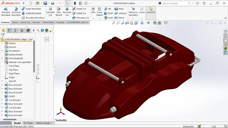
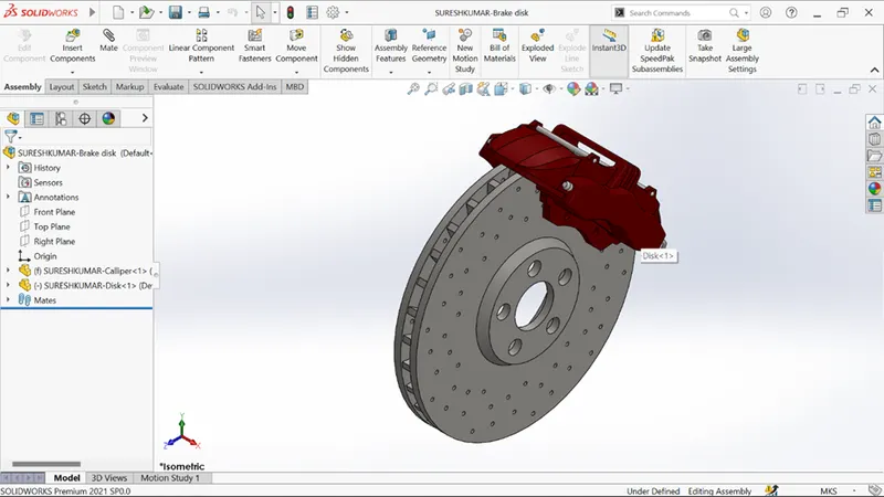
Disk and caliper: The brake caliper houses your car's brake pads and pistons. Its job is to slow the car's wheels by creating friction with the brake rotors(disk). The brake caliper fits like a clamp on a wheel's rotor to stop the wheel from turning when you step on the brakes. I had just used extrude and cut-extrude to develop it with help of blueprint. Also, I just design quarter of the caliper and mirror it. Finally using assembly modelling I assembled disk break with rim and tire.
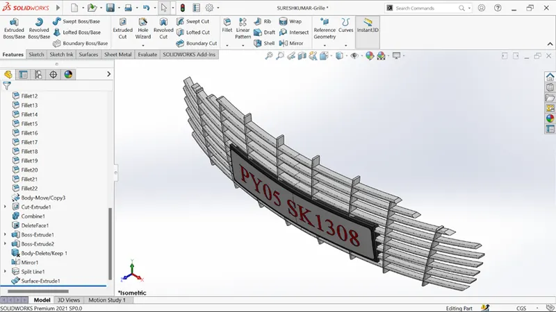
Grille: The air helps to cool the radiator and the engine, so nothing overheats. To cover that hole, manufacturers will install an accessory known as the car grille. It allows the air to flow freely underneath the hood while protecting the engine parts from road debris. Using extrude and fillet I had developed it and mirror it. Here I placed number board also.
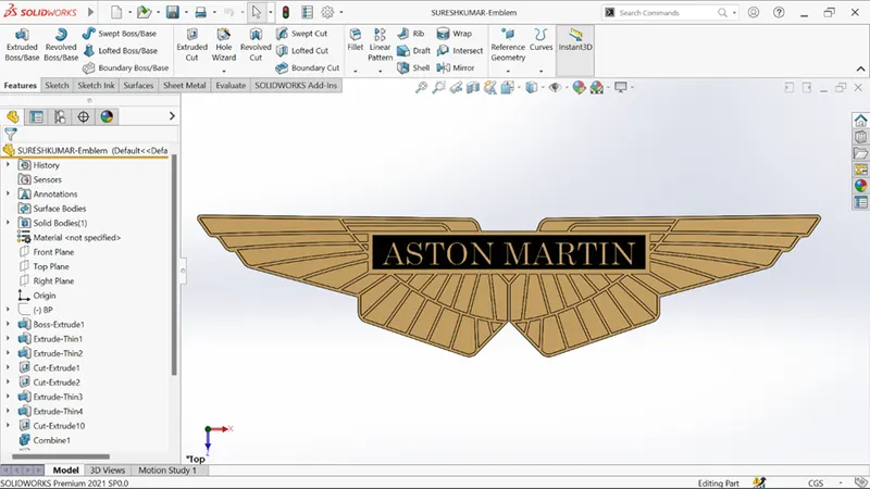
Emblem: The symbolism behind the Aston Martin car logo is really quite simple. Its black, green, and white color scheme only employs colors that traditionally symbolize elegance and refinement. The Aston Martin wings simply symbolize speed, freedom, dreams, and exploration. With the help of emblem blueprint I designed it using simple spline tool.
 ASSEMBLY:
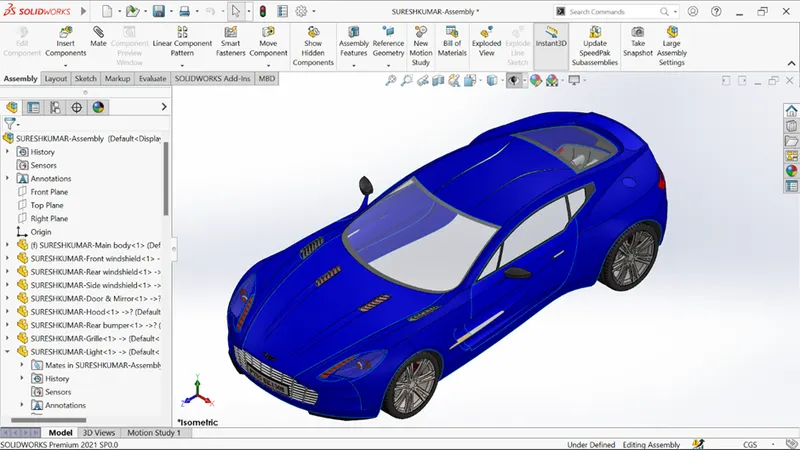
All the parts were modelled and imported into solidworks assembly file to assemble them. In assembly modelling the mate feature is most commonly used to locate and relate the parts with another one. Car body is main component which is inserted first and it will be fixed automatically. The other components were inserted one by one into the assembly file. By using the planes, faces, edges or axis for reference and giving the mate feature. once the part gets fixed then it floats with the main part which part were inserted first. Some parts were modified during assembly to make it perfect according to requirement. Here I created there are three assembly files to complete the Aston Martin car model.
Disk-brake assembly:
Wheel assembly:
Final assembly:
RENDERING:
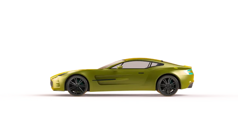
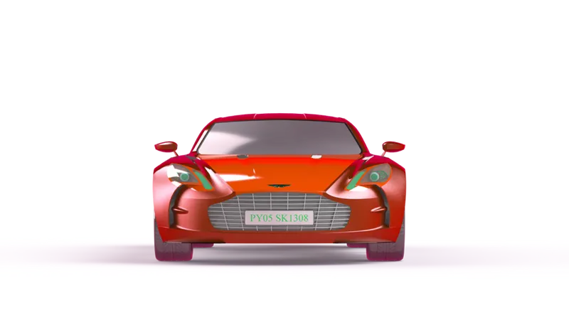
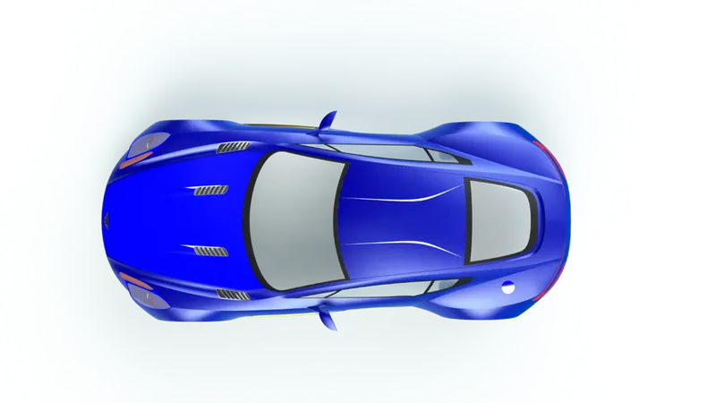
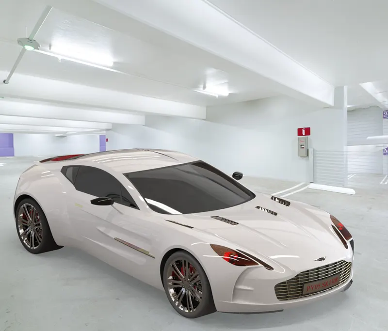
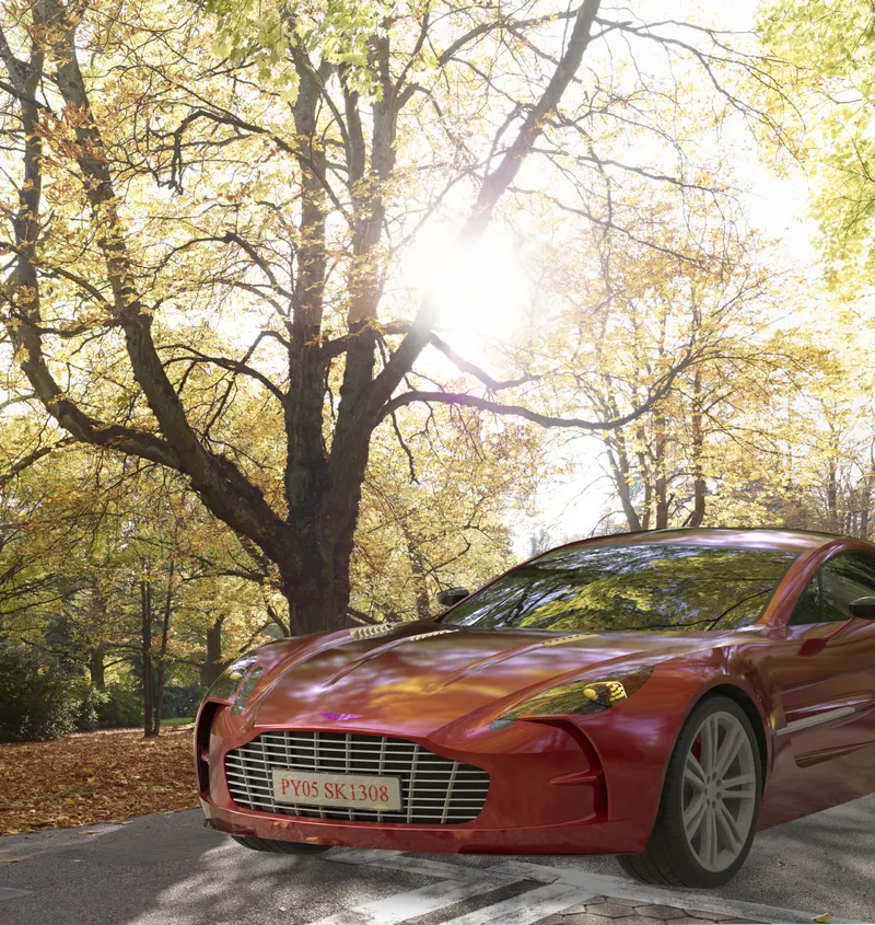
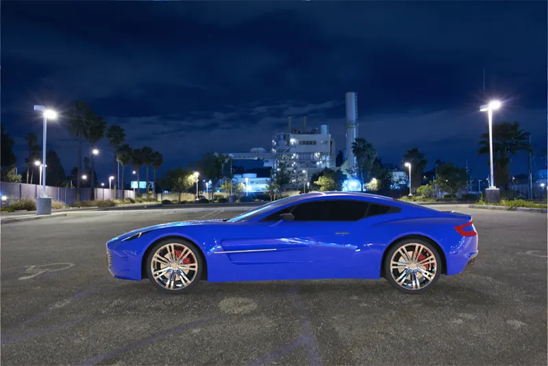
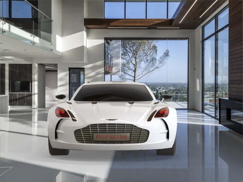
The term “rendering” comes from the graphic world where a rendering is an artistic drawing of what a new structure would look like. In computer aided design, a rendering is a particular view of a realistic image. By doing rendering of Aston Martin, we get the idea that how it will look into the environment. This rendering is done in the “solidworks visualize” software as well as “photoview 360”. By using photoview 360 we can render the model through adding various cameras, lights, decals to that model. Also, to get the perfect realistic view we need to set various angles, direction, and set appropriate distance. In “solidworks visualize” rendering we can change the appearance of parts, background images, environments, brightness, rotation and various setting of Aston Martin. Including the resolution and setting number of passes we get more detail visuals of Aston Martin.
i)Rendering on photoview 360:
 ii)Rendering on solidworks visualize:
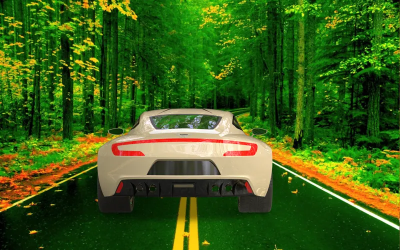
Conclusion: Aston Martin designed has conformed to the projects aims and objective. Aston Martin car has been successfully designed and assembled to optimise the automobile field. The appropriate components for the Aston Martin and their purpose were researched from the references. In addition to component research a broader knowledge was gained about automobile field, this information proved essential for gaining a better understanding of mechanical parts motions. Finally, a design process was implemented in a chronological order starting with empathise define ideate prototype and test.