Assignment 5-RADIOSS Interfaces & Study of Effect of Notches Challenge
F OBJECTIVES:
- Create the mesh for bumper assembly,mesh size should be 6mm.
- Run the crash tube model as it is.
- Change the Inacti=6 and run.
- Create the type 11 contact and run.
- Remove both notches and remove boundary condition on rigid body node then run.
- Create a new notch in the middle ,select the whole section and run.
- Create a new notch with nodes only from opposing 2 faces and run.
PROCEDURE:
1. BUMPER ASSELBLY:
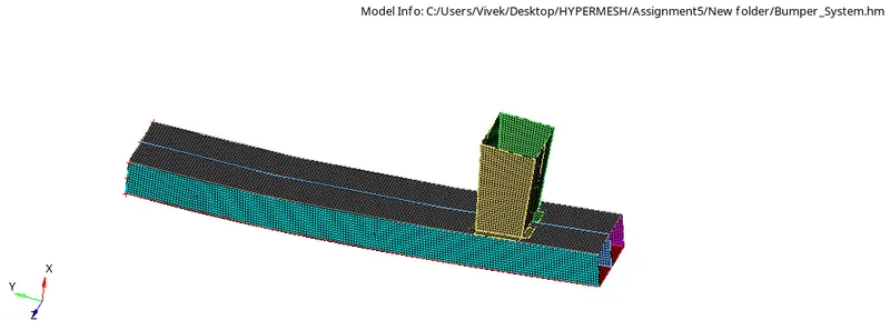
- First we will open the .HM file in Radioss and then perform the Meshing on it.
- The part given is a Car Bumper
- So the meshing is done by using 2D>AUTOMESH.
- Here we have taken mesh size is 6mm as per given criteria
- The meshing is shown below:
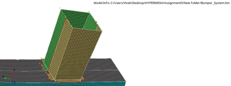
- After that we will connect the box to the beam for that we will go to 1D>CONNECTORS>SPOT .
- And then select LOCATION as NODALIST and TO CONNECT as COMPONENT
- The connected surface is shown below:
2.MODEL 2
CASE 1:
Run the crash tube model as it is.
- For crash tube model we will import the 0000. model in radioss as shown:
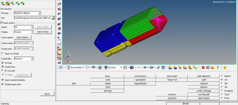
- For this we will go to ANALYSI>RADIOSS
- We are running this model without parameter.
- The coputation time and error parameter is shown below:
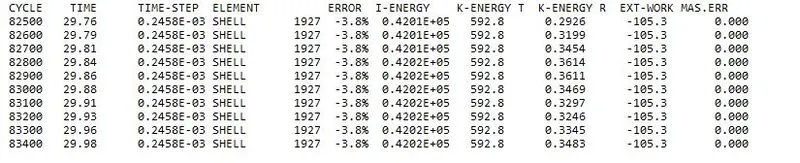
- So here also We seen that the energy error is -3.8% and mass error is 0.000. the acceptable value of the energy error is -15 to 5 % and for mass error is 2 to 3 %, means here error value is in the range then its acceptable.
- Now running the analys by using .h3d file is shown below:
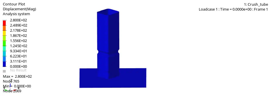
- Here we can see that the maximum displacement is 2.800e+02 and the minimum displacement is 0.000e+00.
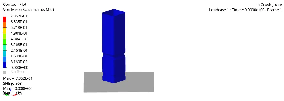
- From the above animation we can see that in Von Misses Maximum value is 7.352e-00 and the Minimum value is 0.000e-00.
- Now we will plot the graph for that we will import T01 file in hypergraph as shown:
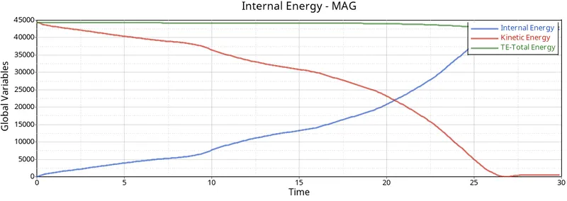
1. Internal, Kinetic and Total Energy
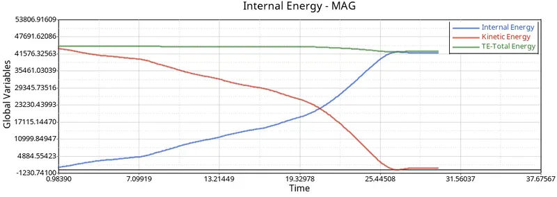
- As we can see here the Internal energy is increasing and Kinetic enrgy is decreasing.
- The Both energies are kind of mirroring of each other.
- So far the total energy is remaining near about constant.
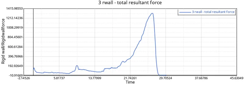
2. Rigid wall force:
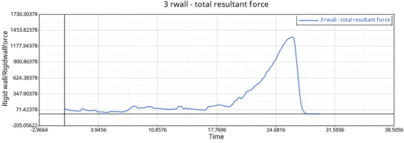
- As we can see here the force increases slowly at from 17ms and decrease rapidly after it reaches to the peak.
CASE 2:
Change the Inacti=6 and run.
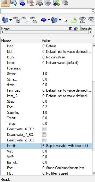
- For this we have to edit the card for this model
- For that go to MODEL>GROUP>SELF CONTACT and edit the Inact as 6. As shown below:
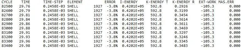
- From the above we can say that the model is acceptable to run the tests.
- Now we will run the analysis again with the given criteria and run .h3d file as shown:
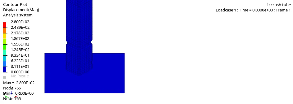
- Here we can see that the maximum displacement is 2.800e+02 and the minimum displacement is 0.000e+00.
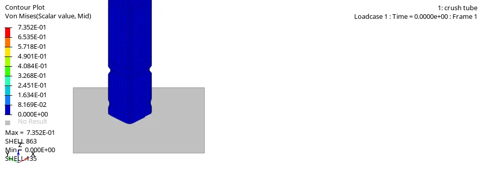
- From the above animation we can see that in Von Misses Maximum value is 7.352e-01 and the Minimum value is 0.000e-00.
- Now we will plot the graph for that we will import T01 file in hypergraph as shown:
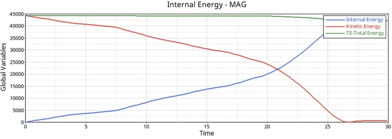
- As we can see here the Internal energy is increasing and Kinetic enrgy is decreasing.
- The Both energies are kind of mirroring of each other.
- So far the total energy is remaining near about constant.
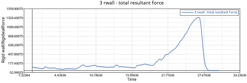
- As we can see here the force increases slowly at from 17ms and decrease rapidly after it reaches to the peak.
- From the graph we can observe that it is same as CASE 1 so there is no penetration happening.
CASE 3
Create the type 11 contact and run.
- Now to create Type 11 card we have to go to the SOLVER>INTER and there we can create a new card.
- Now after the card is created we will perform the analysis.

- From the above data the we can run the analysis.
- We will now now open .h3d file.
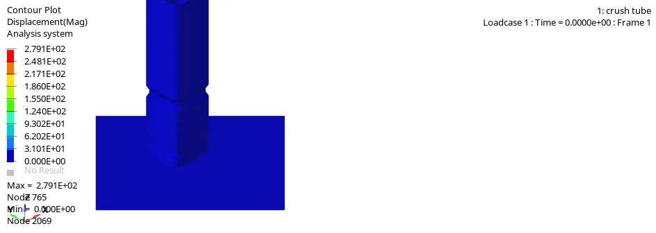
- Here we can see that the maximum displacement is 2791e+02 and the minimum displacement is 0.000e+00.
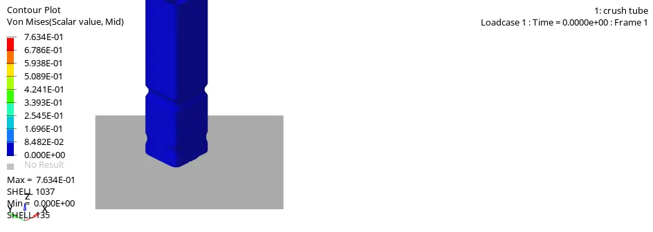
- From the above animation we can see that in Von Misses Maximum value is 7.634e-01 and the Minimum value is 0.000e+00.
- Now we will project the graph:
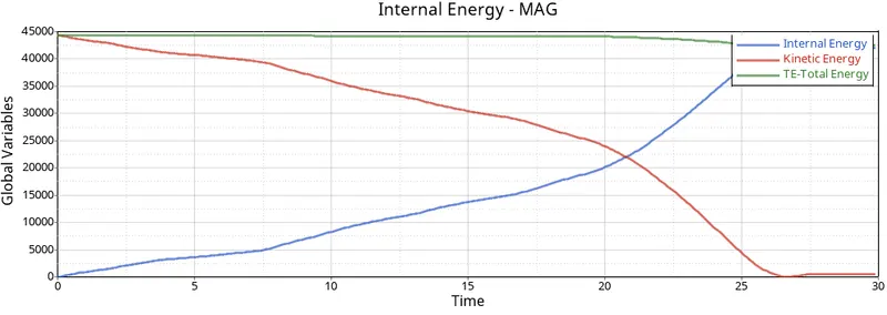
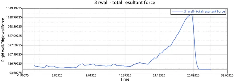
- So far the graphs are similar.
CASE 4
Remove both notches and remove boundary condition on rigid body node then run.
- Remove the notches use the align option
- For this we will go the solver deck and delete the BCS. And then perform the anlaysis. As shown:
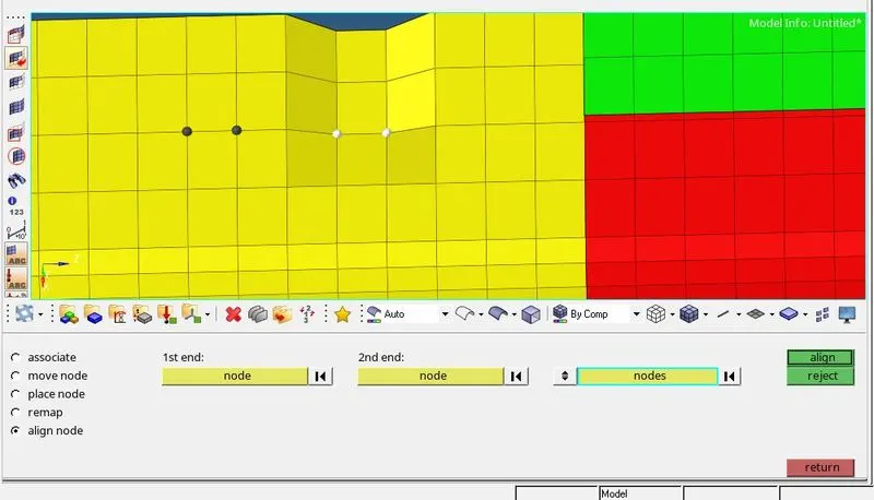
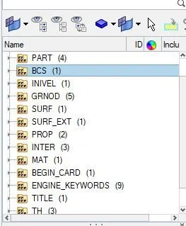
- Now we will perform the analysis.
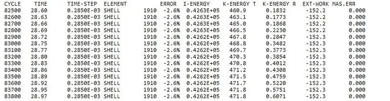
- It is accepted.
- Now we will run .h3d file.
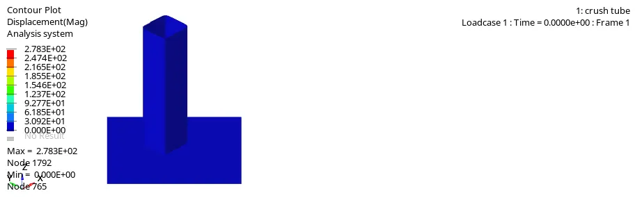
- Here we can see that the maximum displacement is 2.783e+02 and the minimum displacement is 0.000e+00.
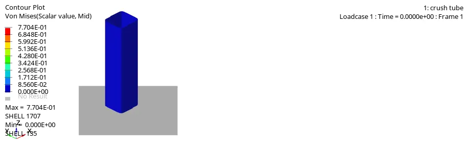
- From the above animation we can see that in Von Misses Maximum value is 7.704e-01 and the Minimum value is 0.000e+00.
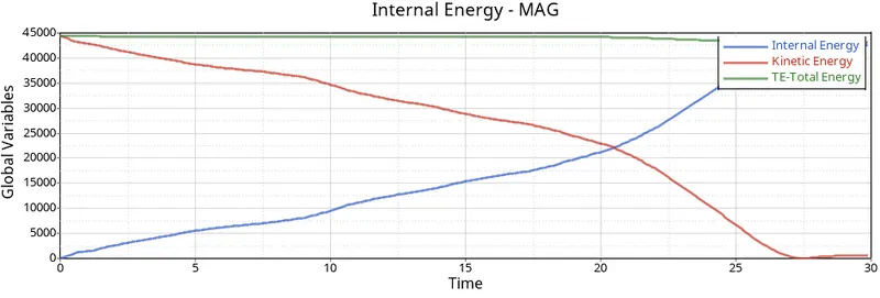
- Now we will project the graph:
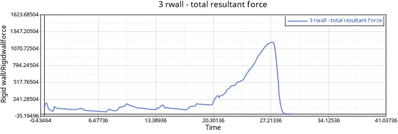
CASE 5
Create a new notch in the middle ,select the whole section and run.
- For this we are going to use TOOLS>Translet as shown:
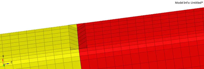
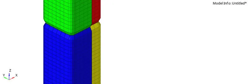
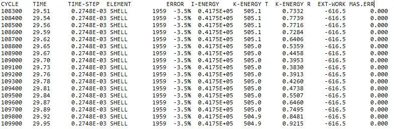
- It is accepted.
- Now we will run .h3d file.
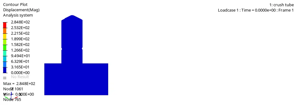
- Here we can see that the maximum displacement is 2.84e+02 and the minimum displacement is 0.000e+00.
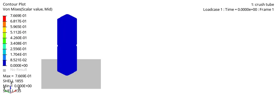
- From the above animation we can see that in Von Misses Maximum value is 7.604e-01 and the Minimum value is 0.000e+00.
- Now we will project the graph:
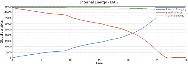
- As we have seen in previous cases, Internal energy keeps increasing due to the deformation that takes place. Kinetic energy also decreases due to increase in internal energy.
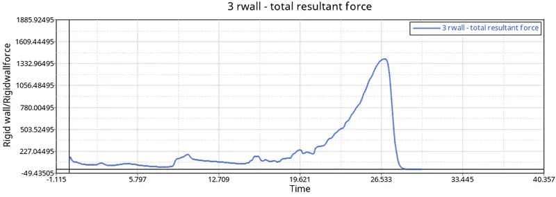
- There is no noticeable difference between case 4 and case 5. it’s almost similar. After some point, RWALL force peaks at some value due to the absorption of energy created during collision and when the tube crushed completely, the value decreased and got constant.
CASE 6
Create a new notch with nodes only from opposing 2 faces and run.
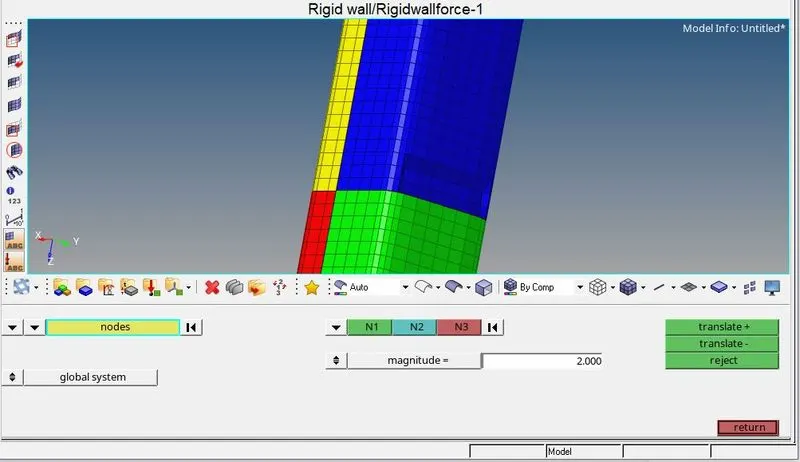
- Now for this we will again use TOOLS> Translet
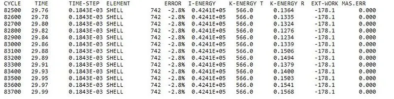
- From the above values the component is accepted.
- .h3d file
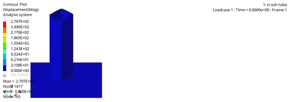
- Here we can see that the maximum displacement is 2.74e+02 and the minimum displacement is 0.000e+00.
- We can see here the component break at in the middle.
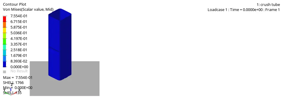
- From the above animation we can see that in Von Misses Maximum value is 7.554e-01 and the Minimum value is 0.000e+00.
- Now we will project the graph:
| Sr No | CASE | RWALL Forces (KN) | Contact Forces(KN) | Internal Energy(J) |
| 1 | Case 1 | 1350 | 93.45 | 45200 |
| 2 | Case 2 | 1350 | 93.45 | 45200 |
| 3 | Case 3 | 1350 | 97.91 | 45200 |
| 4 | Case 4 | 1200 | 58.62 | 45200 |
| 5 | Case 5 | 1250 | 72 | 45200 |
| 6 | Case 6 | 1350 | 101.2 | 45200 |
- In case 4 (Removing notches) experience less RWALL forces and Contact forces.
- In case 6 (Notch on opposing faces) experience maximum contact forces.
- From the graphs it can be concluded that,creating the notch between the crash tube causes changes in increasing and decreasing in internal energy and kinetic energy.
- From all the cases we can say that criteria "Inacti" is required to be defined as it removes any initial intersections in the model if they exist.
- It helps to obtain a more accurate result and also reduces the no. of cycles & time taken to solve.
- The type 11 contact is given between 2 edges and requires lesser parameters to be defined and also takes comparatively lesser time to be solved than a type 7 contact.