Running crash tube simulation using different contact interface definitions & meshing bumper assembly
Aim: To run the crash tube simulation using different contact interface definitions & performing meshing operation on the bumper assembly provided
Objective:
- Comparison of results of crash tube simulation for the different cases of contact interfaces
- Mesh the bumper model provided
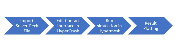
Workflow(for simulation):
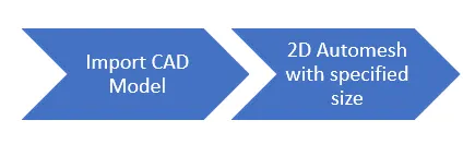
Workflow(for meshing of bumper):
Theoretical Aspects
Interface/ Contact Modelling:
Interfaces are defined to model how parts interact when they meet each other
Penalty Method
Interfaces using penalty method is based on master/slave treatment
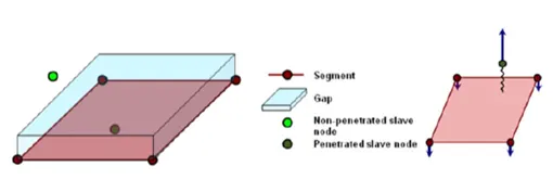
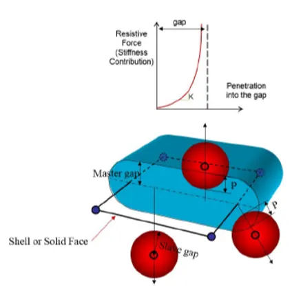
- A gap distance is defined to decide whether a node is in contact with a segment
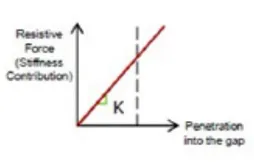
- The penalty method treats the behavior between slave nodes and master segments as springs that generate resistive forces as a function of penetration
- Spring elements are created between the salve node and its projection. The spring stiffness is automatically computed according to the material and property of both master segment and slave node
- The contact ends when the penetrated node is completely pushed out of the gap. Therefore the elastic spring & the reaction forces are removed
Note: Contact stiffness to be kept in check because if it’s very high, it could lead to time step collapse altogether.
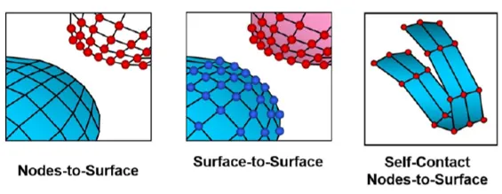
Types of interfaces
Friction
Various formulations for friction are available in RADIOSS, but the most used one is the Coulomb friction law. This formulation provides accurate results in crash analysis & requires one parameter (Coulomb friction coefficient, Mu); Iform=2 stiffness friction formulation is recommended
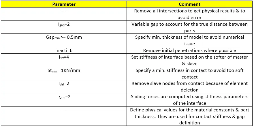
Important interface parameters
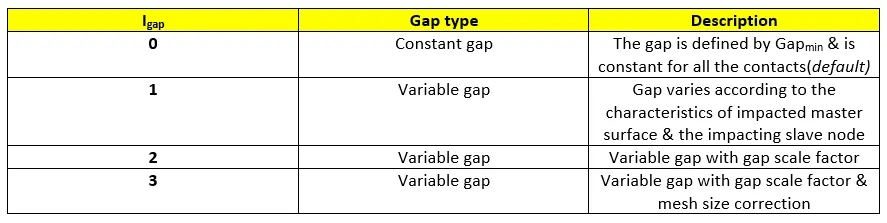
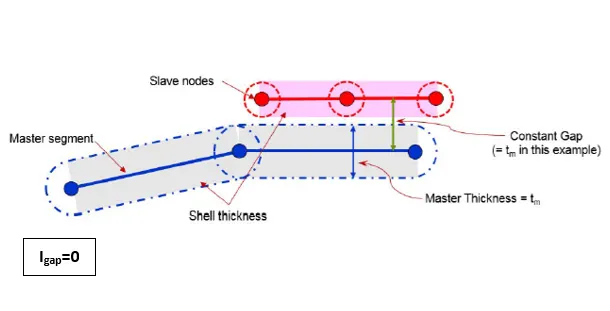
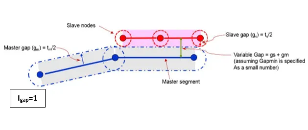
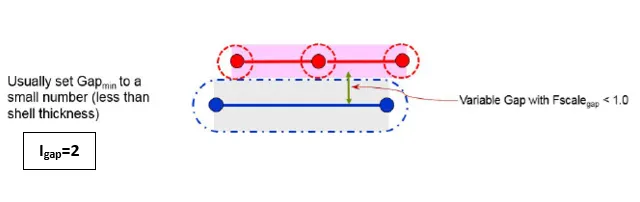
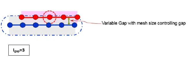
- Igap: Determines how the size of the gap is calculated
- Gapmin: Minimum gap for activation of interface
- Inacti: Action to take if initial penetrations exist
- Istf: Affects how the stiffness of the interface is calculated
- Iform: Friction formulation
- Stmin: Minimum stiffness to use in the interface
- Idel: What to do with slave nodes and master segments if elements fail(deleted) that they are attached to
Interface Type 7: Nodes to surface contact
- A general purpose interface and can simulate all types of impact between a set of nodes and a master surface
- Non-oriented and slave nodes can belong to the master surface-hence auto-impact possible(self-contact)
- Variable stiffness using penalty method
- Gap around master segment can be kept constant or variable
- Resistive forces are applied to keep the slave nodes out of the contact gap
- Interface time step is computed to insure stability
- The main advantage of Type 7 is that stiffness is not constant and increases with penetration preventing the slave node from going through the master mid-surface
- The gap used is on both sides of the master segment mid-surface shell & a cylindrical gap is added around the edges to remove energy jumps induced by a node impacting from the shell edges
Limitations
- It only considers the nodes of one component striking the other component, it does not give regard to how elements are shaped
- More the no. of slave nodes, more calculations to assess if the slave node has penetrated the gap or not
Various Igap values:
Interface Type 7: Initial Penetrations
- Results when slave nodes are past the master segment
- Can cause locking leading to computation failure
- If slave nodes lie on the master segment an ERROR will occur because of the type 7 contact stiffness definition
- Initial penetrations should be removed using Hypermesh or Hypercrash
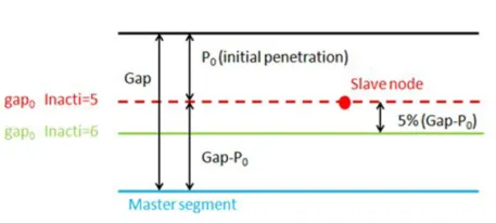
- It can be seen from the below figure that from upper side, penetration>gap which implies the time step evaluates to negative using the formula mentioned below leading to instability.
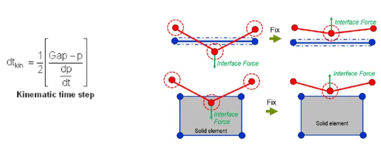
6. Penetrations result if a slave node is closer to the master segment than the calculated gap
7.Initial repulsion forces give an error in the energy balance due to interfaces work
8.There are options in the solver to remove initial penetrations
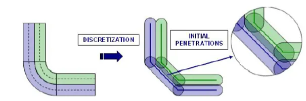
Inacti values for removing initial penetrations:
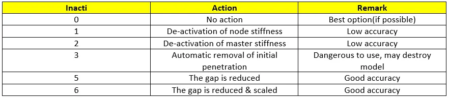
Note: The initial penetration, P0 should be smaller than 30% of the initial gap to avoid contact stability issues
Interface Type 7: Resistive forces
The resistive force is non-linear with respect to the penetration of the slave node into the gap and is a function of the penetration value and rate.
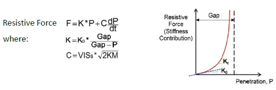
Interface Type 7: Initial contact stiffness, K0

The final value of contact stiffness, K can be evaluated by lower and upper bound limits, Stmin, Stmax:

Interface Type 7: Sliding force Computation(Friction forces)

Interface Type 7: Time step calculation
- Because the interface stiffness is non-linear, the slave node cannot cross the master segment. This gives good accuracy for the node location
- However this means that the interface time step needs to be evaluated during the solution. If there is large penetration, the interface stiffness becomes large, leading to reduced time step. That is why we need to keep Stmax(Max. stiffness limit) in good check
- The slave node cannot cross the master segment because the stiffness can even reach infinity to not let this happen(Specialty of Type 7)
- If the stiffness is not in good check it could lead to very high resistive forces which could result in unwanted deletion of elements

Interface Type 7: Accountability for deleted elements(Idel)
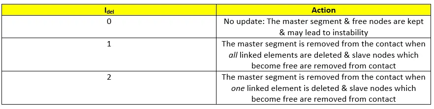
Interface Type 7: Recommendations for crash applications
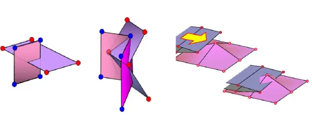
Limitations of Node to surface- Type7
There are situations in which this type of contact interface will not detect the contact due to edges crossing each other at angles. Type 11 interface can be added to capture the physics correctly.
Interface Type 11: Edge to Edge contact
- Simulates impact between edge to edge or lines. A line can be a beam or truss element or shell edge or spring elements
- Defined by identifying master & slave lines(edges)
- Impact occurs between a master & a slave line
- Works in similar manner to type 7 in terms of penalty formulation, gap definition
Note: The master is typically meshed coarser because it is meant to be the stiffer component, so that the slave does not penetrate the master. That is why we choose the less deformable or high stiffness structure as the master and less stiff one as slave. In general, the component under study, is to be meshed finer and hence is the slave.
Note: Interface Type 19 is a combination of Type 7 & 11
Interface Type 24: General Contact
- It has linear stiffness variation which is not ideal for crash applications.
- Single surface, surface to surface or nodes to surface contact interface using penalty method with constant stiffness
- A gap is defined around the master segment & slave node. The contact gap is the sum of the master gap & the slave gap
- The time step is not affected
Bumper meshing
Model Provided
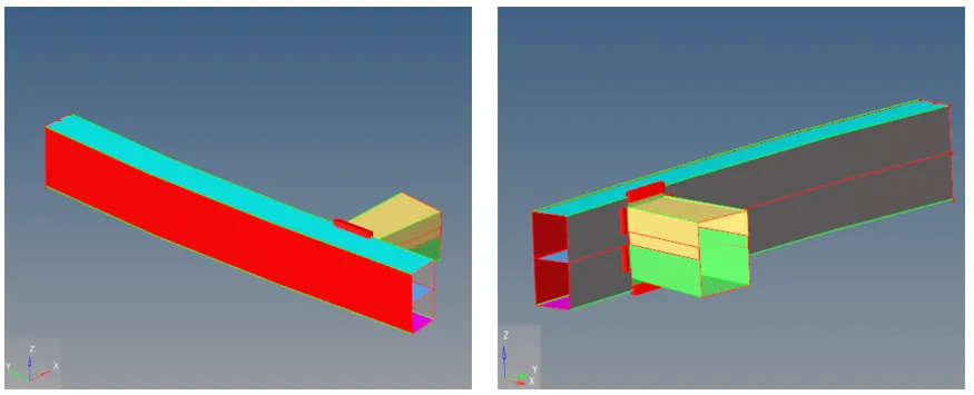
Target mesh size= 6mm(Quads only formulation has been followed)
Meshed Bumper
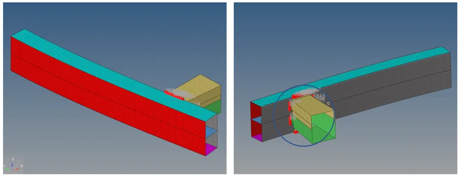
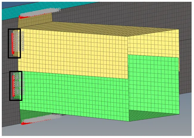
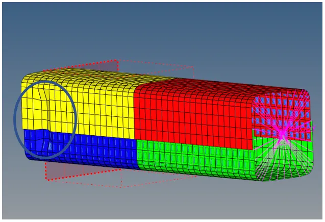
The encircled part is shown as follows, this is where the upper crash box and lower crash box has been spot-welded to the bumper:
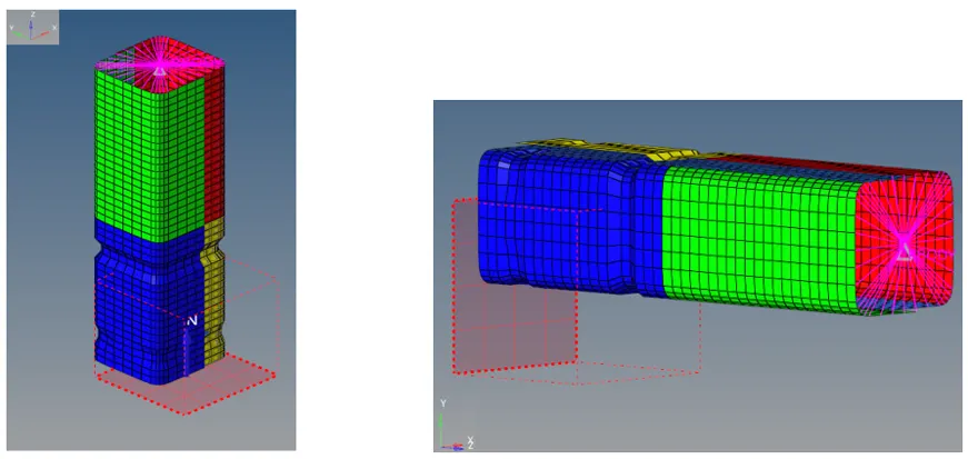
Model Provided for Simulation
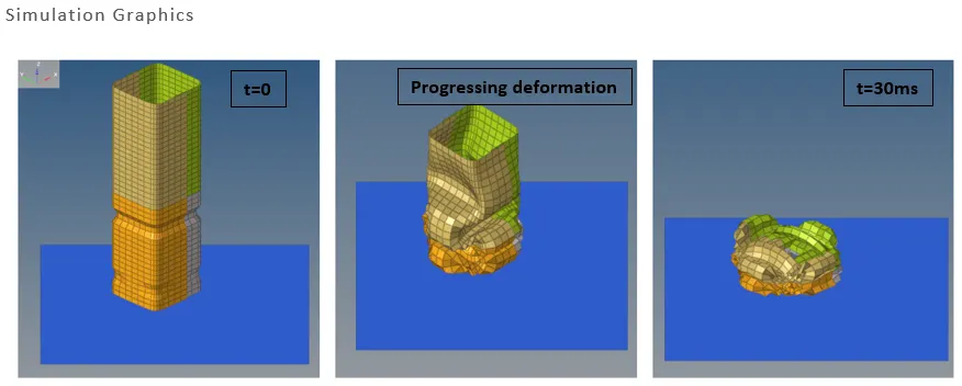
Case 1
(Running the base simulation)
Energy & Mass error checks
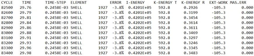
Energy error= -3.8%, which is within acceptable limits of -15%.
Mass error= 0.00
Elapsed time= 71.78 s
Von-Mises stress contour
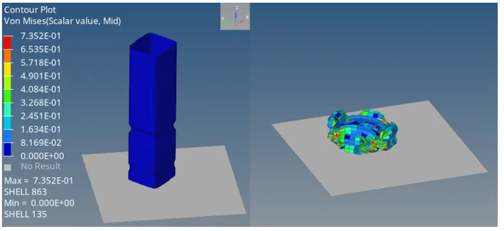
Max Von mises stress= 0.7352 N/mm2
Plots
Rigid wall force
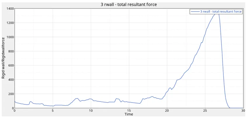
The rigid wall force attains maxima at around 27th ms, maximum value being 1400 units
Internal, kinetic, hourglass, contact, Total energy plot
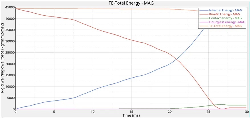
- The internal energy increases with time as the material absorbs the energy from shock wave while the kinetic energy falls in value as the crash tube comes to rest after crash, it is maximum in the beginning when the crash tube has some initial velocity.
- The contact energy increases after 20th ms,
- The hourglass energy remains zero as the QEPH element formulation takes care of it even before hourglass deformation takes place.
Case 2
(Setting Inacti=6 and running the simulation)
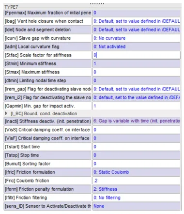
Energy & Mass error checks
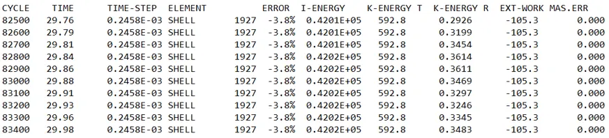
Energy error= -3.8%, which is within acceptable limits
Mass error= 0.00
Elapsed time= 70.74 s
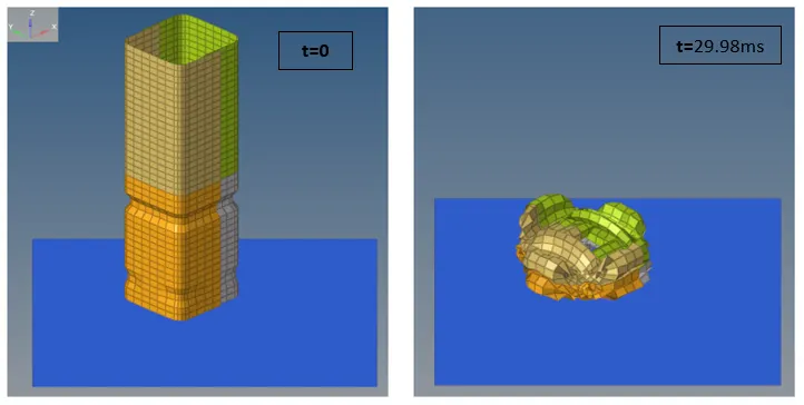
Simulation graphics
Von-Mises stress contour
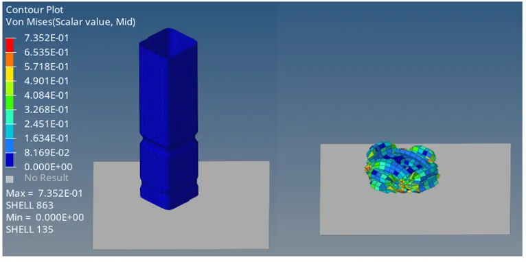
Max Von mises stress= 0.7352 N/mm2
Plots
Rigid wall force
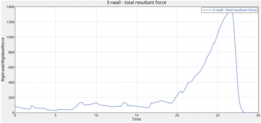
The rigid wall force attains maxima at around 27th ms, maximum value being 1400 units; same as the first case.
Internal, kinetic, hourglass, contact, Total energy plot
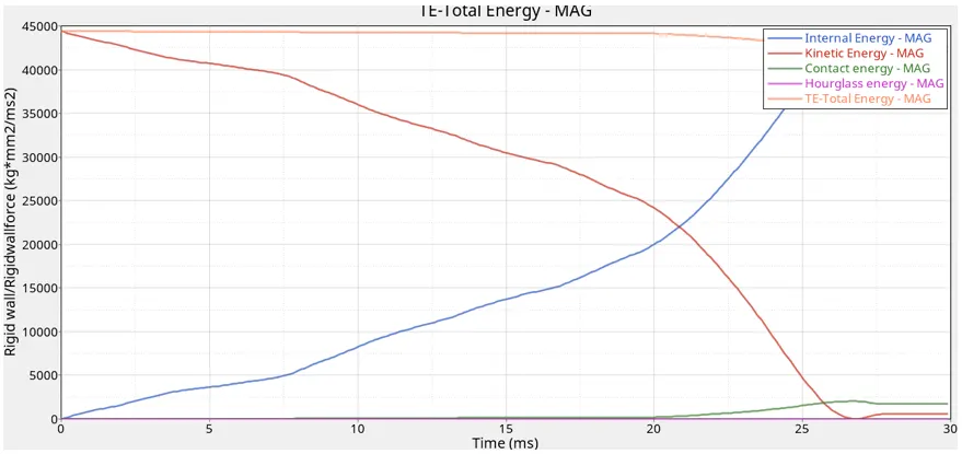
Superficially, there is no change in energy plots compared to case 1
The internal energy increases with time as the material absorbs the shock wave energy. Kinetic energy is observed to be decreasing because in the beginning the crash tube had a high velocity giving a high kinetic energy naturally, as the crash tube comes to rest i.e. after the crash has taken place kinetic energy gets converted to the potential energy. Some amount of energy is dissipated which can be construed on the fact that energy error is negative.
Hourglass energy is zero as it has been taken care of by the QEPH element formulation.
Case 3
(Defining Type 11 contact interface)
Contact Card
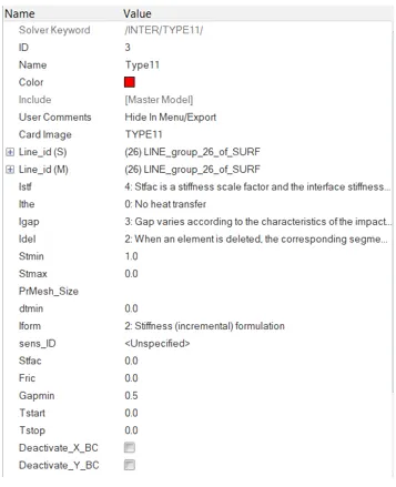
Energy & Mass error checks

Energy error= -1.4%, which is within acceptable limits of -15%
Mass error= 0.00
Elapsed time= 175.05 s
Simulation Graphics
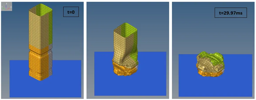
Von-Mises stress contour
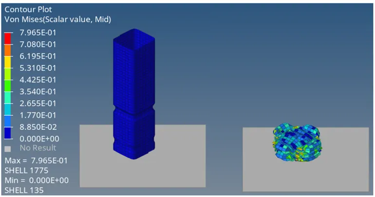
Max von-mises stress= 0.7965 N/mm2
Plots
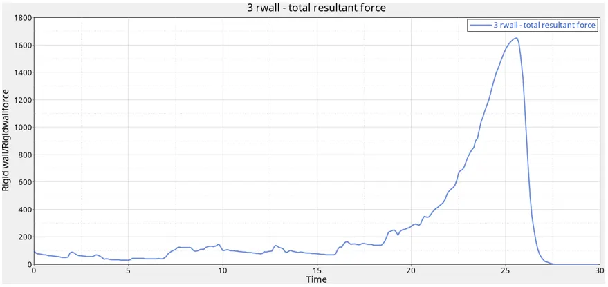
Rigid wall forces
Internal, kinetic, hourglass, contact, Total energy plot
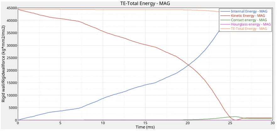
The kinetic energy is maximum in the beginning because of the high initial velocity and decreases as the crash comes to rest, the kinetic energy gets converted to the internal energy over time which can be construed on the fact that internal energy is increasing as the crash continues. The contact energy increases due to self-contact of crash tube. The hourglass energy is zero as QEPH element formulation has been used.
Case 4
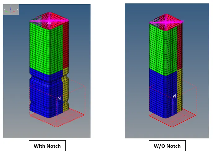
(Removing both notches & boundary condition on rigid body node)
The notches have been removed using the align node command in hypermesh.
Energy & Mass error checks
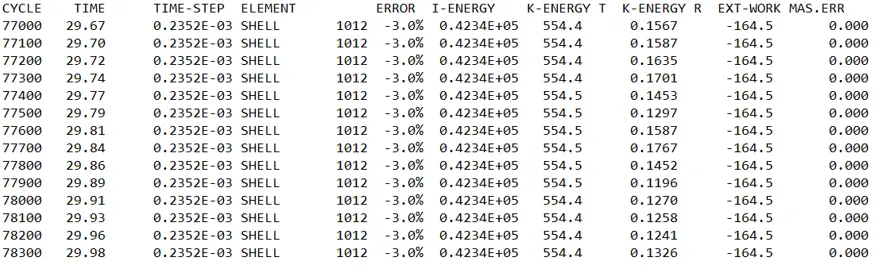
Energy error= -3.0%, which is within acceptable standards.
Mass error= 0.00
Elapsed Time= 102.99 s
Simulation Graphics
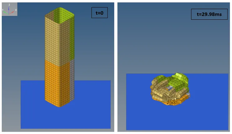
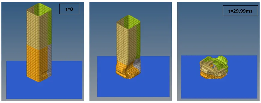
As there is no notch, the deformation is quite random compared to other cases having notch because there is no contour shape on crash tube to control it.
Von-Mises stress contour
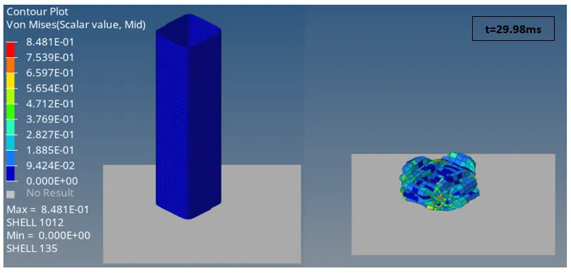
Max von mises stress= 0.8481 N/mm2
Plots
Rigid wall force
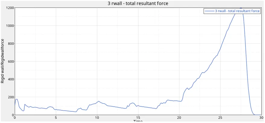
The rigid wall force reaches maximum value at 27th ms (1200 units) which is less than the case 1 & 2.
Internal, kinetic, hourglass, contact, Total energy plot
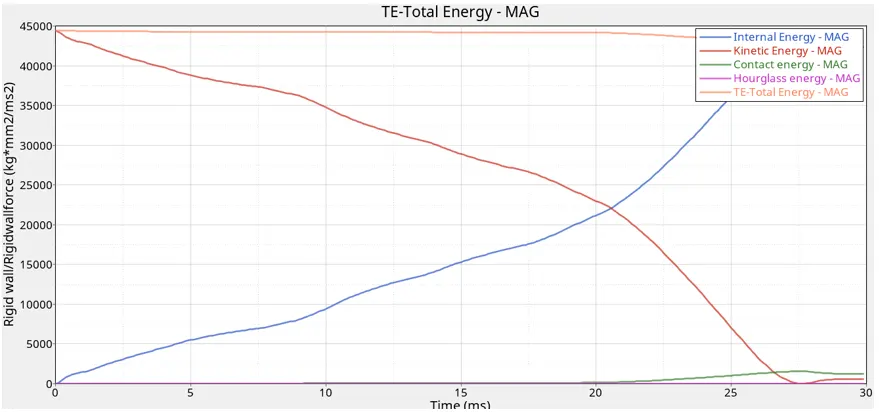
The internal energy increases with time as the material absorbs the energy whilst the kinetic energy drops. The contact energy increases after the 20th ms which can be due to the reason that during the end of the simulation a lot of elements are folding upon each other, leading to energy dissipation.
The hourglass energy is zero throughout because it has been kept under check by the QEPH element formulation.
Case 5
(Creating new notch at the middle of crash tube)
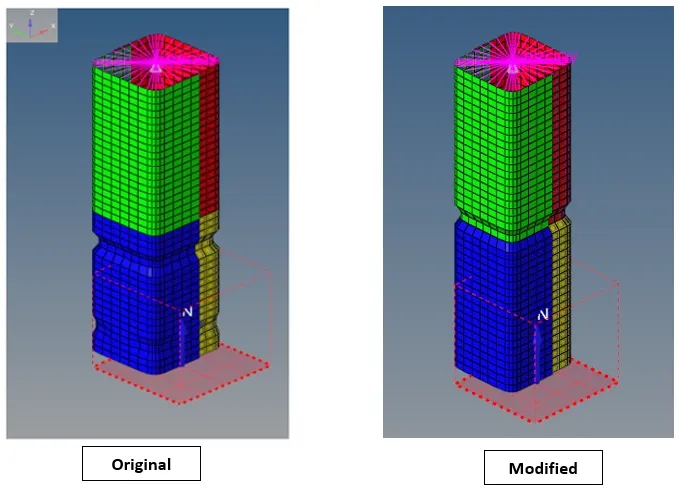
Energy & Mass error checks

Energy error= -3.9%, which is within acceptable limits of -15%.
Mass error= 0.00
Elapsed time= 127.41 s
Simulation Graphics
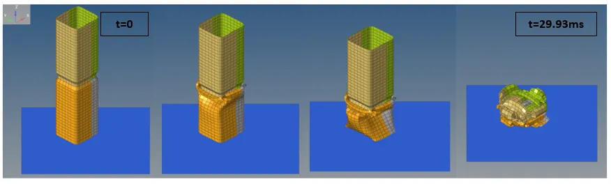
It can be observed that in this case, the tube first starts folding on itself where the middle notch was created.
Von-mises stress contour
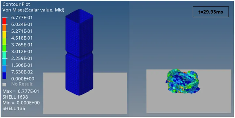
Max von-mises stress= 0.6777 N/mm2
Plots
Rigid wall force
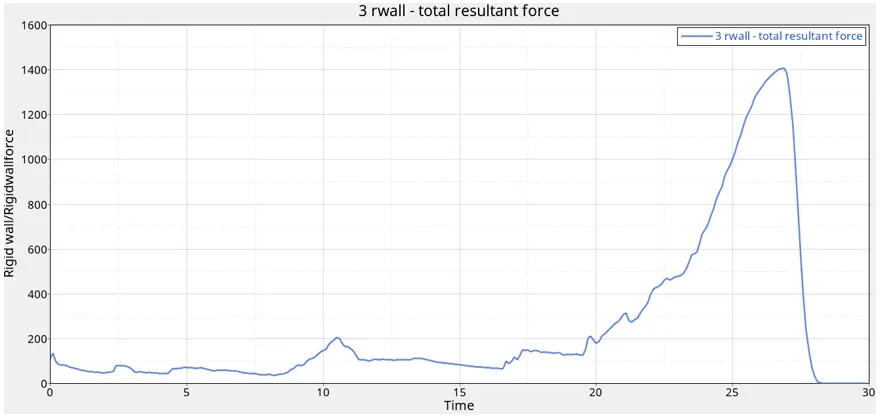
The rigid wall force reaches a peak value(1400 units) around the 26th ms of the simulation.
Internal, kinetic, hourglass, contact, Total energy plot
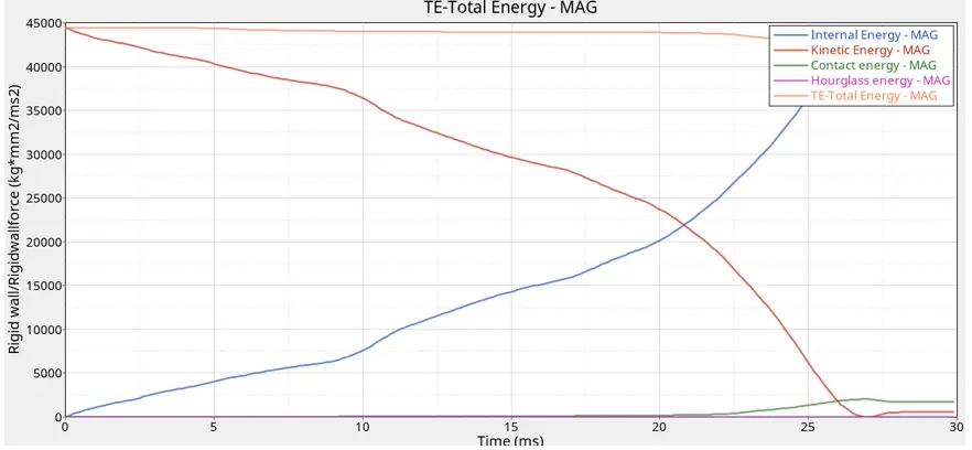
The internal energy and kinetic energy has the general trend i.e. increasing & decreasing with time, contact energy increases due to elements folding upon each other. The hourglass energy is eliminated by using QEPH element formulation.
Case 6
(Notch on opposite faces only)
Energy & Mass error checks

Energy error= -3.1%, which is within acceptable standards
Mass error= 0.00
Elapsed time= 116.49 s
Simulation Graphics
Von-Mises stress contour
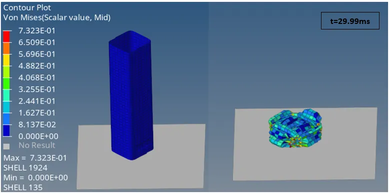
Max von-mise stress= 0.7323 N/mm2
Plots
Rigid wall force
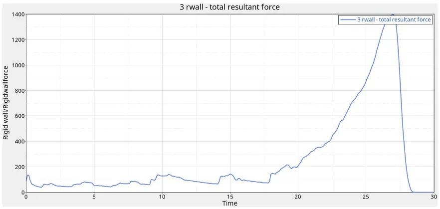
The rigid wall force reaches a peak value at around the 27th ms.
Internal, kinetic, hourglass, contact, Total energy plot
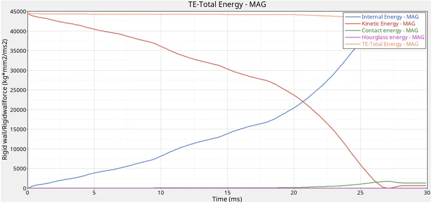
The Hourglass energy is zero because QEPH element formulation is used as before. The Kinetic energy falls as the crash completes simultaneously increasing the internal energy as the material absorbs the shock wave intensity. The contact energy increases due to self-contact(elements folding upon each other).
Result Comparison
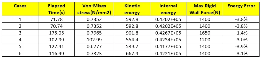
- The internal energy among the cases is superficially the same.
- The rigid wall forces in different cases is highlighted in the above table. The maximum rigid wall force offered by the wall is in case 3(Type11+Type7 used) being 1650N.
- The maximum kinetic energy is also offered in case 3 being at whopping 901.8 units
- The least energy error is obtained in case 3 as combination of Type 7 & 11 has been used here, which gives more realistic results for the simulation.
Conclusion
- Successfully completed the simulation for 6 different contact cards and compared the results: energy plots, rigid wall forces for the different cases.
- Completed the meshing of bumper assembly using the given element size preference.