Quasi-static roof crush analysis of BIW model of a generic car
Aim: Quasi-static roof crush analysis of BIW model of a generic car
Objective:
- Perform transformation operations on the impactor to place it over B pillar
- Creation of appropriate interfaces & boundary conditions
- Analyzing elemental energy, equivalent plastic strain, hourglass energy, von mises stress, added nodal mass
- Plotting various energy vs time and force vs displacement curves
Abstract
Roof crush is the failure and displacement of an automobile roof into the passenger compartment during a roll over accident. The current federal regulation involving roof strength FMVSS 216 is found to offer a little benefit and is currently under review.
This project encompasses the various aspects of a roof crush of a car and study of stress, displacement contours and various force and energy plots.
Workflow
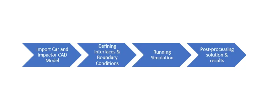
Case Set-up & Execution
Unit Check
(can be seen in 0000.rad file)
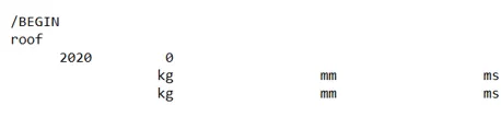
The unit system thus followed from hereon in [Kg, mm, ms]
Model provided
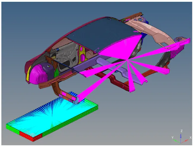
Impactor position transformation
The following transformation operations have been used thorough hit & trial method to position the impactor over the B pillar of the Car model correctly:
- Translate command (Tools>>Translate)
- Rotate command (Tools>>Rotate)
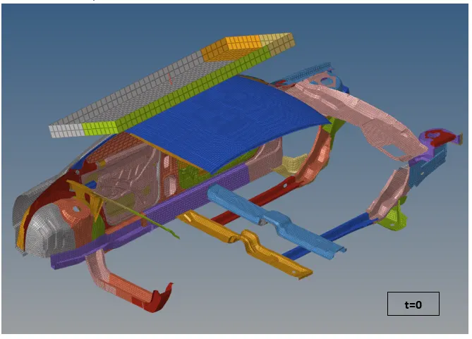
The following graphic shows the positioning of the impactor as desired:
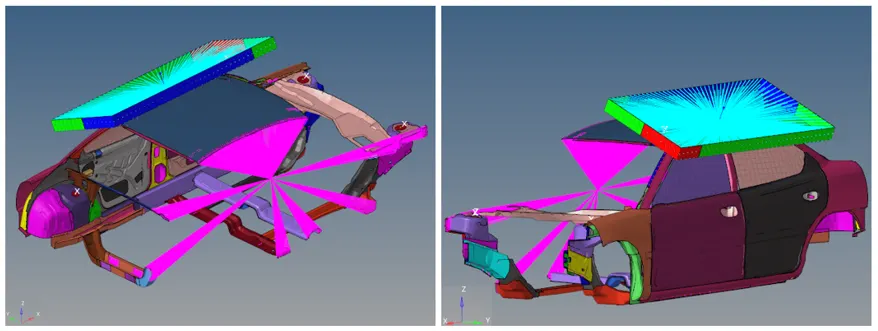
Note: The impactor must be placed as close to the B pillar as possible to reduce the simulation calculation time keeping in mind that the there should be NO initial penetrations.
Interface Creation
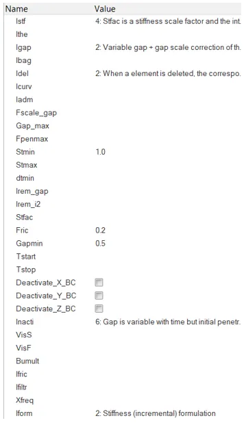
The contact type used in this analysis is Type 7.
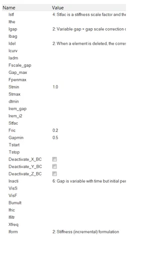
Recommended parameter values
- Istf=4
- Igap=2
- Idel=2
- Stmin= 1.0 kN/mm
- Fric= 0.2
- Gapmin= 0.5 mm
- Inacti= 6
- Iform=2
Type 7 contact: For car self-contact
In this contact type the car itself is the master and the slave.
Type 7 contact: Impactor & car
In this contact, the impactor is made the master and car is the slave.
Boundary Conditions
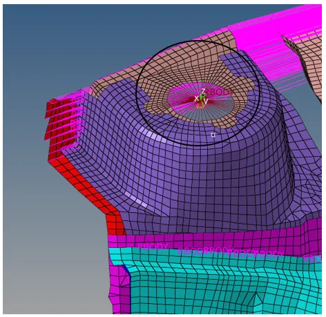
Suspension Tower
As per requirement, we must keep the suspension tower nodes locked in Z.
To achieve this, as shown in the following graphic a rigid body has been created where the suspension towers are located and a moving skew has been defined with the origin node being the master node of the rigid body, in such a way that the Z direction of the skew points in vertically upwards direction.
The boundary condition for all the suspension tower nodes was defined using the following BCS card:
(Solver>>Create>>Boundary Conditions>>BCS)
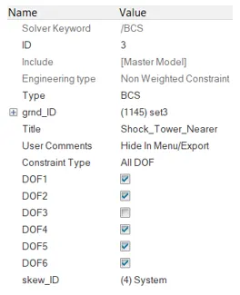
The moving skew defined for each suspension tower rigid body created above is assigned to the respective BCS card of the suspension tower under skew_ID.
For the grnd_ID the master node of the rigid body was selected and as per requirement all the DOF’s were locked and the suspension was left to move freely only in the Z direction.
Note: Similar rigid body creation, moving skew assignment and DOF locking was performed for all the suspension tower nodes in the model.
Impactor Boundary conditions
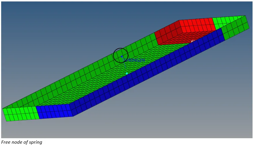
- The impactor has been attached with a spring for stability which has a free end. To take care pf that we create a new BCS card to fix the free end of the spring by locking all the DOF’s associated with it (refer card image attached below):
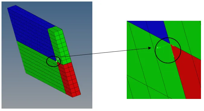
- To define a direction normal to the impactor’s face, a moving skew was created so that the Z axis of skew points towards the car as shown in the following image:
- A new BCS card is created to guide the master node of the impactor rigid body so that it see free to translate normal to the face of the impactor, but is fixed in all other DOF’s(Card image below):
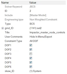
Under grnd_ID the master node of the rigid body on the impactor is selected.
Imposed Displacement
Displacement is imposed on the master node itself of the rigid body on the impactor.
For the velocity of the impactor the following definition has been used to create a function to assign in the IMPDISP card:
Velocity= { 0 mm/ms at t=0,
200 mm/ms at t=200ms}
The following function curve was created:
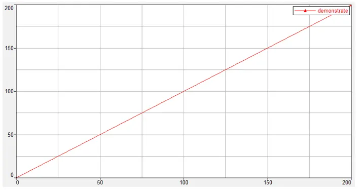
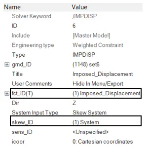
This function curve is assigned in the following IMPDISP(imposed displacement) card. Moreover the moving skew created earlier is also assigned here to define the direction of imposed displacement.
Engine File
- Constant nodal time step method has been used
- Time history is printed every 0.1ms
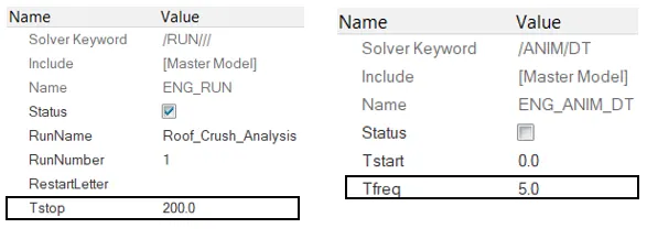
- Tstop= 200ms (as shown in the ENG_RUN card below)
- Animation file is created every 5ms i.e. Tfreq= 5ms (as shown in ENG_ANIM_DT card below)
Output Requests
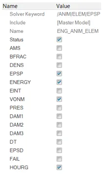
The following animation outputs has been requested and parallel arithmetic was turned on:
- Element Energy
- Elemental equivalent plastic strain
- Elemental hourglass energy
- Elemental von mises stress
5. Nodal added mass (ENG_ANIM_NODA)

Simulation
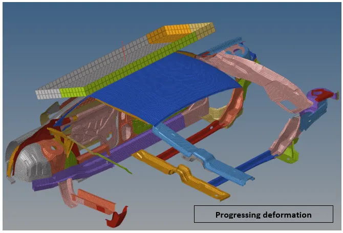
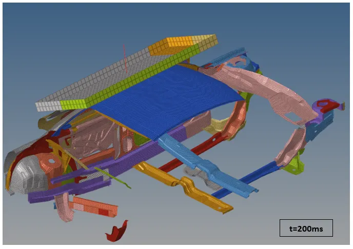
Simulation Graphics
Energy & Mass Error checks

Energy Error= -13.5%, which is within the acceptable range of -15%.
Mass Error= 0.04635x100= 4.6%, which is less than 5%.
Output Request Animation
Displacement Contour
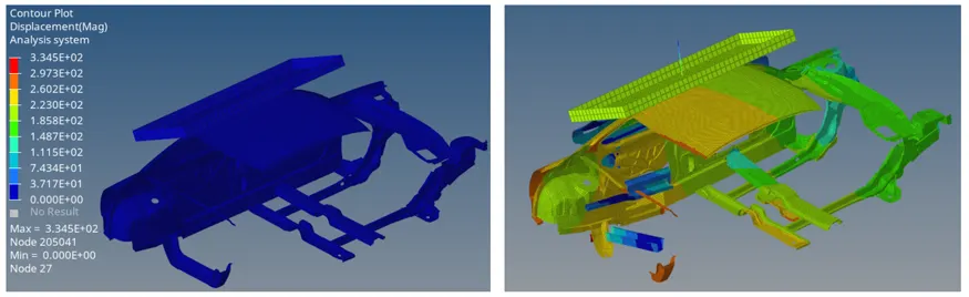
Max Displacement= 334.5 mm
Von mises Contour
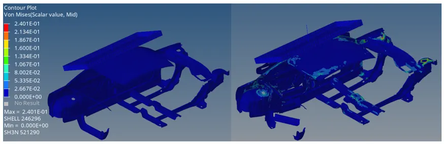
Max von mises stress= 0.2401 N/mm2
Plastic Strain
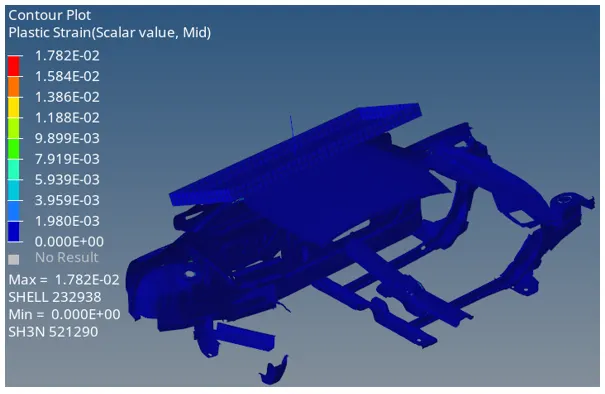
Max Plastic strain= 0.01782
Hourglass Energy
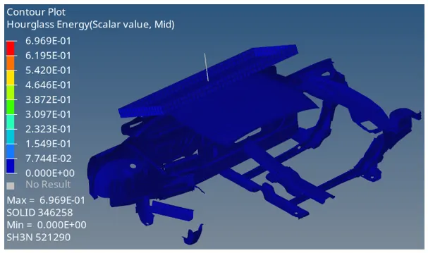
Max hourglass energy= 0.6969 units
Specific energy
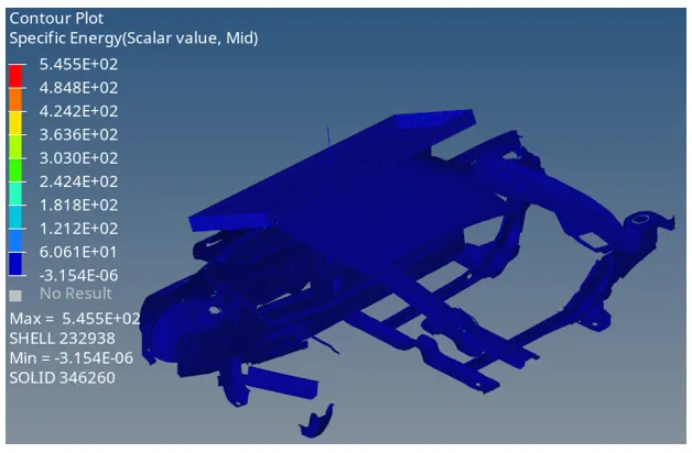
Max specific energy= 545.5 units
Node Mass (Added)
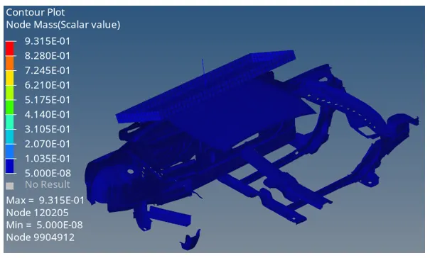
Max Node mass= 0.9315 Kg
This mass has been added to accommodate for the failing time steps i.e. when the time step falls below the specified time step the solver adds a mass at the node to increase the value of time step.
Energy vs time Plots
Internal, Kinetic, Total energy
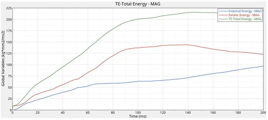
Max internal energy= 100 Kg*mm2/ms2
Max kinetic energy= 146 Kg*mm2/ms2
Initially, the Internal and kinetic energy rise gradually. The kinetic energy decreases from the 140th ms as the impactor comes to rest it reaches a value of around 125 Kg*mm2/ms2 whereas internal energy keeps on increasing in a gradual fashion.
Hourglass energy
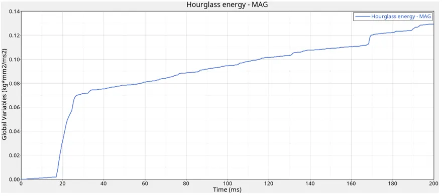
Max hourglass energy= 0.13 Kg*mm2/ms2. The hourglass energy comes out to be less as it has already been taken care of by the QEPH element formulation.
Contact energy
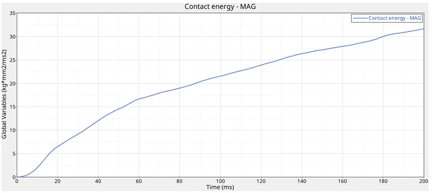
Max contact energy= 31 Kg*mm2/ms2. This energy is due to the energy released when elements collapse on each other thus coming into contact.
It is recommended that {(Contact energy + Hourglass energy)/(Total energy)}x 100 < 15%...........expression(1)
Contact energy at end of simulation= 31 Kg*mm2/ms2
Hourglass energy at end of simulation= 0.13 Kg*mm2/ms2
Expression(1) evaluates to 13.897% which is less than 15%. Hence, acceptable.
Mass
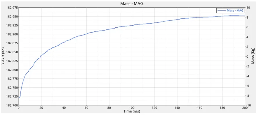
The initial mass of the car before simulation was 159.744 Kg and the final mass is around 183Kg at 200th ms. This may be due to the added nodal masses to correct the failed time steps.
Interface- self contact Resultant force
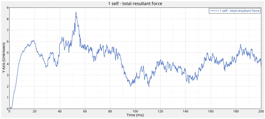
Max force= 8.5kN (approximately) around the 52nd ms of the simulation.
Interface- Car & Impactor Resultant force
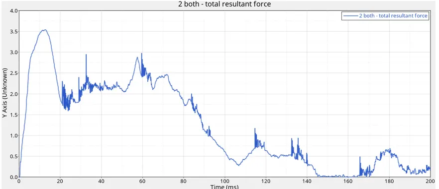
Max force= 3.5kN around the 10th ms of the simulation.
Force Vs Displacement Cross Plot
Displacement Vs Time
Displacement here is of the impactor.
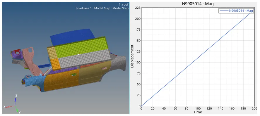
The displacement of Node 9905014 in the direction of motion is being studied here.
Interface(Car & Impactor) total resultant force vs time
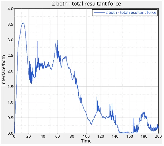
Cross Plot(Force Vs Displacement)
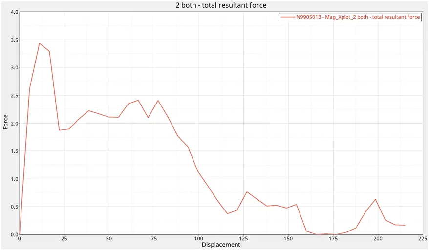
The maximum force is around 3.4kN at displacement 12.3 mm of the impactor.
Gross Vehicle Weight
The mass of the vehicle model= 159.744 Kg
Weight of the vehicle(GVW)= 159.744 x 9.81 = 1567.088 N
3 X GVW= 1567.088 x 3= 4701.264 N= 4.701kN
From the cross plot the maximum force = 47,000N = 47kN
It is observed that maximum force > 3XGVW. Thus FMVSS 216 target load criteria has not been met as we are using a reduced BIW car model.
Conclusion
Successfully carried out roof crush analysis of BIW car model with the study of various contours and energy plots. Force vs Displacement cross plot study was also included in the discussion. The model was not satisfying the FMVSS 216 standard as here we have used reduced model, to resolve this issue the weight of the car model can be increased.