To carry out geometry cleanup and meshing operation under the given quality criteria using Hyperworks
Aim: To carry out geometry cleanup operation on 3 given models, extract the Mid-surface, generating a 2D mesh and assigning proper thickness using generic property
Objective: To perform geometry cleanup, mid surface extraction and 2D meshing under given quality criteria for the models provided
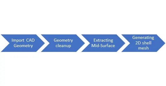
Workflow:
Geometry Clean-up Aspects:
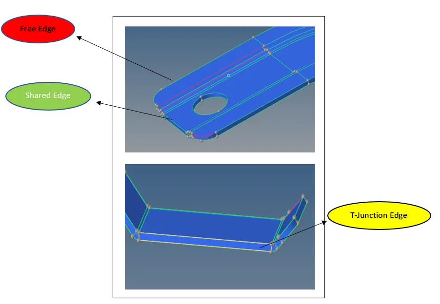
Topology: “Topology” is a way surfaces connect to adjacent surfaces
- If a surface edge is associated with more than 1 surface, those surfaces are in “Equivalence”
- Surface edges are colored according to the number of associated edges:
- Free Edge(Red): These are associated with only one surface. Surfaces having free edge in between are not connected/equivalenced.
- Shared Edge(Green): As the name suggests, these edges are associated with 2 surfaces which are equivalenced.
- T-Junction Edge(Yellow): These edges are associated with 3 or more surfaces which are connected through this edge.
- Suppressed Edge(Blue): Surfaces connected with this type of edge are as though they are combined into one surface.
Features Used in geometry clean-up:
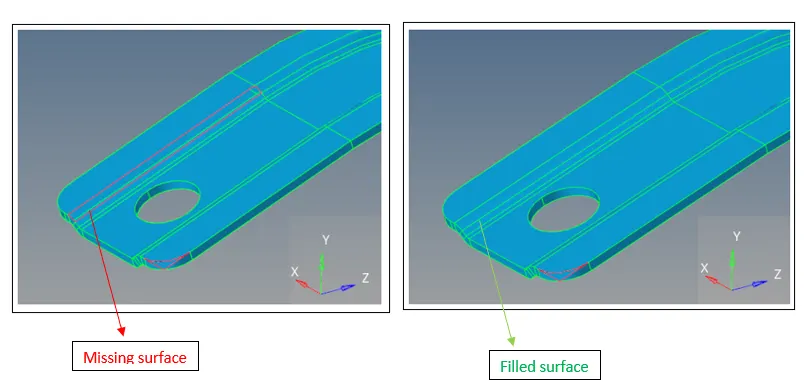
- Filler surface:
(Geometry>>Quick Edit>>Filler surface)
Select lines/ surface edges to create any missing surfaces. It can also be used to fill up unwanted geometrical features like holes
- Toggle:
(Geometry>>Quick Edit>>Toggle)
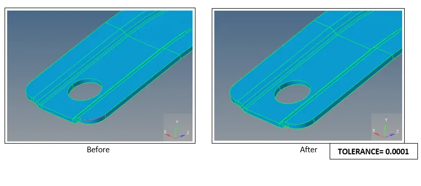
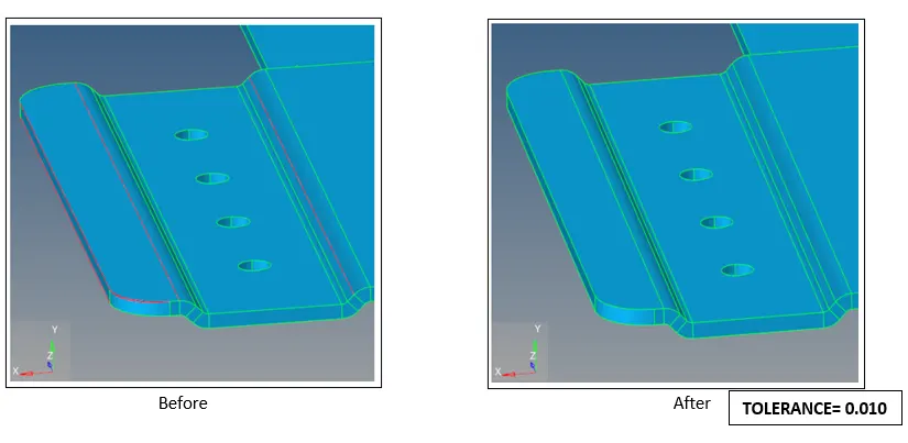
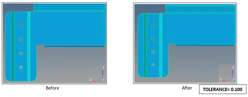
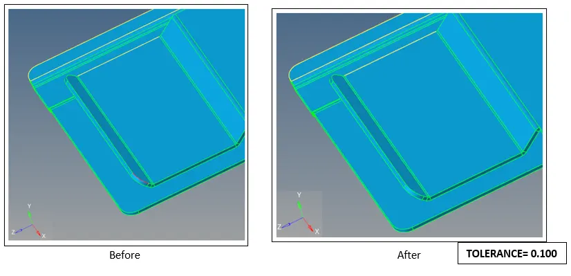
(1 edge/ pair of edge at a time) Equivalences the selected edge with other free edges found with a specified user tolerance
- Replace point:
(Geometry>>Quick Edit>>replace point)
Replaces one specified point with another selected point
- Delete surface:
(Delete option(F2)>>surfs)
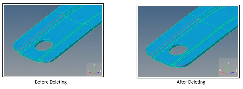
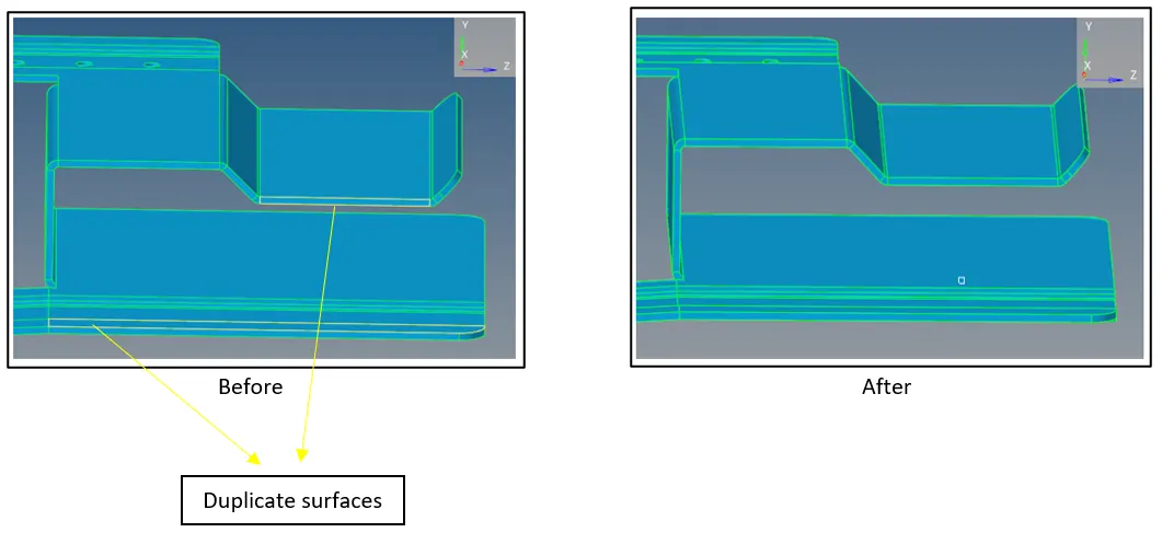
Helps in deleting unwanted surfaces like duplicate surfaces to reduce redundancy
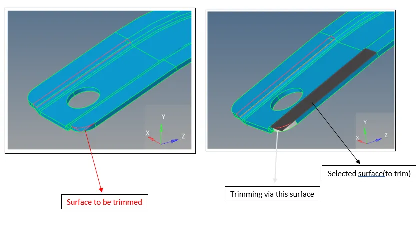
- Split surface:
(Geometry>>Surface Edit>>trim surfs/planes)
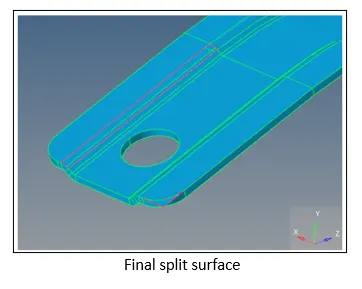
Splits the selected surface with a surface used as a cutter surface(to be given by user)
Model 1-Geometry Cleanup, mid surfacing, 2D meshing
Model Provided
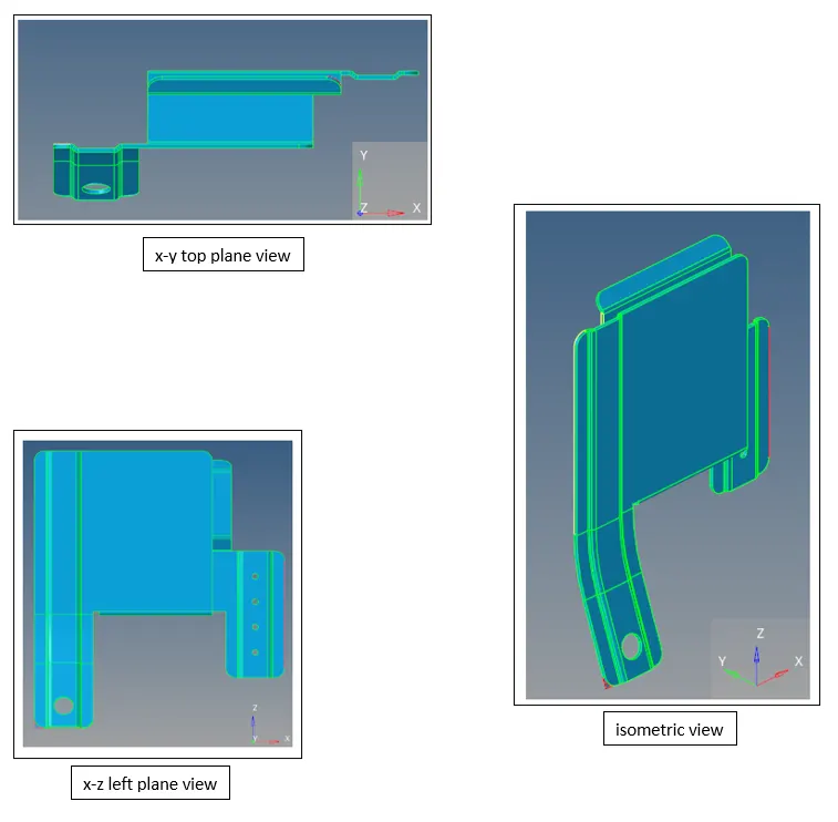
Geometry clean-up operations: Model 1
- Filler surface:
2. Trim surface:
3. Deleting extra surface(from previous step):
4. Toggle Edges(stitching up operation):
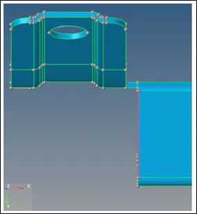
5. Replace Point:
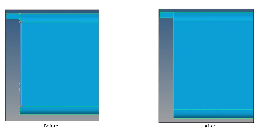
6. Deleting duplicate surfaces
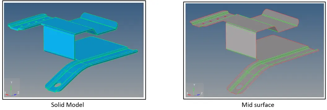
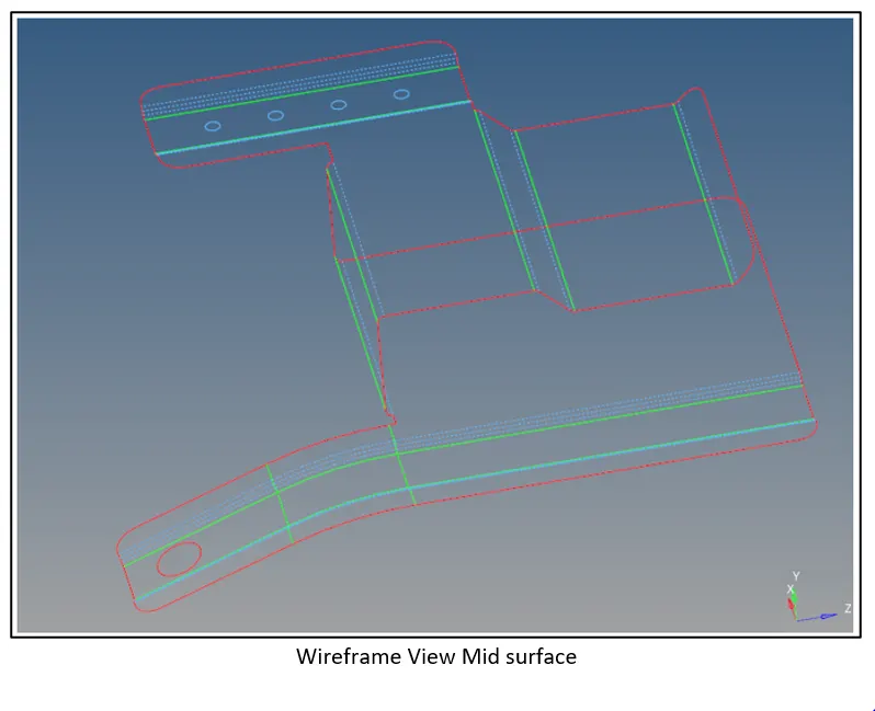
Mid Surface Extraction Model 1
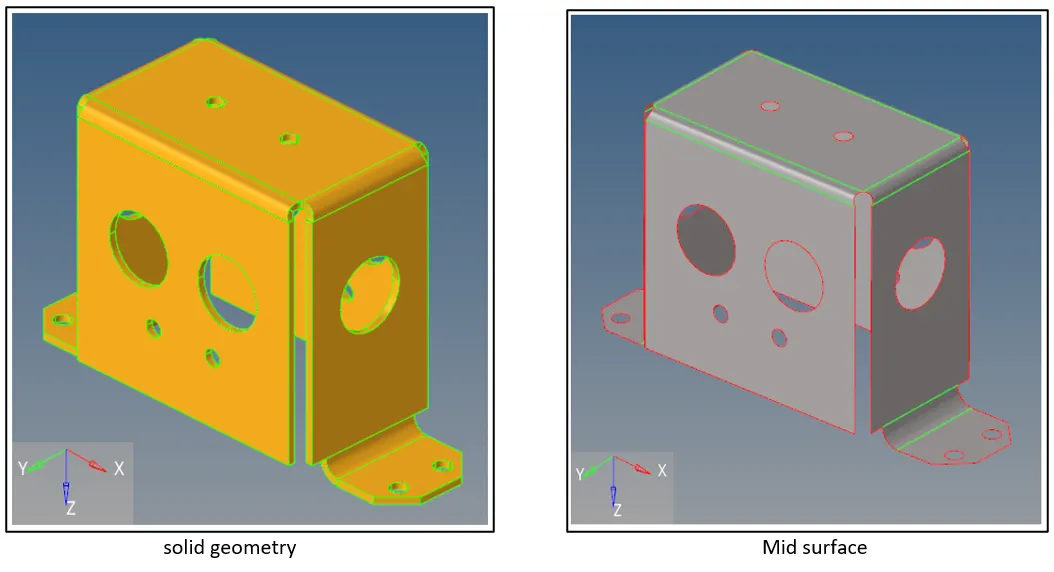
Mid surface: This feature allows to extract a mid-surface from thin solids or enclosed surfaces. The original geometry that we select to extract the mid-surface from remains unchanged, and the new geometry that represents the mid-surface is placed in a component called Middle Surface, or in the current component, depending on user’s selection
- For various FEA problems, parts are represented by shell elements(Like air bag and crash analysis)
- CAD geometry is a solid part consisting of series on surfaces constituting a volume
- Mid surface feature creates a layer of surface on midplane which can be directly meshed
Meshing Aspects
Basic idea of Meshing:
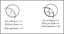
The basic idea of FEA is to make calculations only at finite number of points and then interpolate the results for the entire domain (surface or volume). Any physical object has infinite number of points and it’s not possible to solve the problem in this way. Therefore Finite Element Method was devised which breaks down the problem to solving algebraic equations at finite number of points with the help of discretization or meshing
Element type:
In this meshing exercise 2D elements (or shell elements) are incorporated for the meshing of mid-surface
- In 2D shell elements two of the dimensions are very large in comparison to the third one:
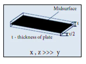
- Element shape: Quad, Tria
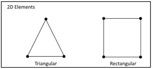
- Additional information from user: Remaining dimension i.e. thickness
Auto-mesh:
This panel is a key tool in HyperMesh, it allows you to specify and control element size, type, density, node spacing and also perform quality checks
- A part can be meshed all at once or in portions. For performing 2D mesh all at once it is advisable to properly clean the geometry using required tools as mentioned above
- In this panel while re-meshing the auto generated mesh you can also specify the type of new element you want when re-meshing, it can be Quads, Trias, or Mixed
- You can also decide whether the new elements should be of first order or second order as per requirement
The mesh bias has following options:
- Quads: Quad dominant mesh, Trias used only when necessary
- Trias: Equilateral Tria mesh
- Mixed: Use of Quad and Tria both
- R-Trias: Isoceles Tria mesh
- Quads only: Only Quad elements created
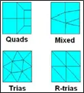
Meshing criteria followed:
- Target element size= 5mm
- Min element size= 5mm
- Max element size= 7mm
- Holes having diameter less than 5mm are ignored
Note: In this assignment only aforementioned quality criteria is strictly followed
Meshing Tool Used:
- Auto-mesh
- Smooth
- Project
- Translate
- Element quality check
- Edge equivalence
Meshing: Model 1
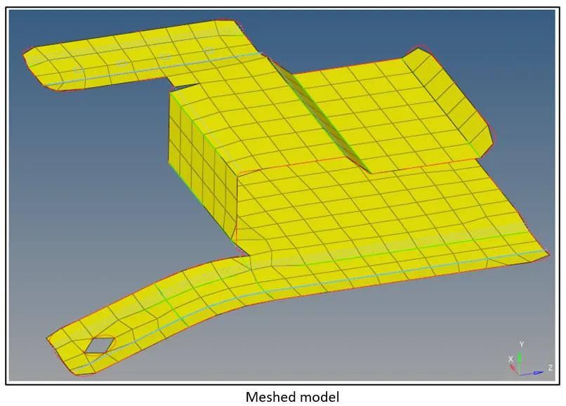
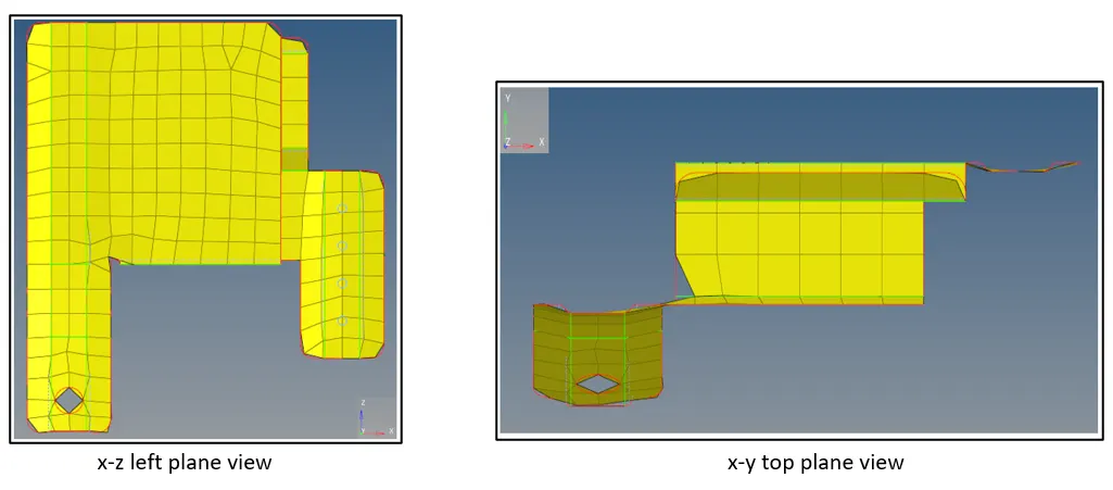
After meshing the mid-surface using the aforementioned tools appropriately, we get the following mesh:
2D>>quality index:
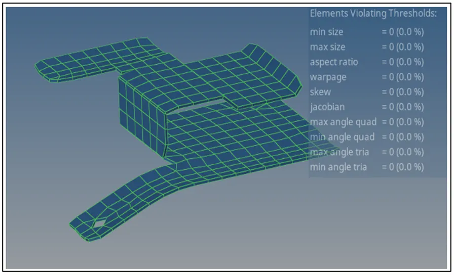
- This meshing was done strictly on the basis for not violating the threshold for min and max element size, as can be seen from the above graphic that no. of elements violating the threshold for min and max element size is ZERO
Organizing elements & assigning thickness by creating a generic property(Model 1)
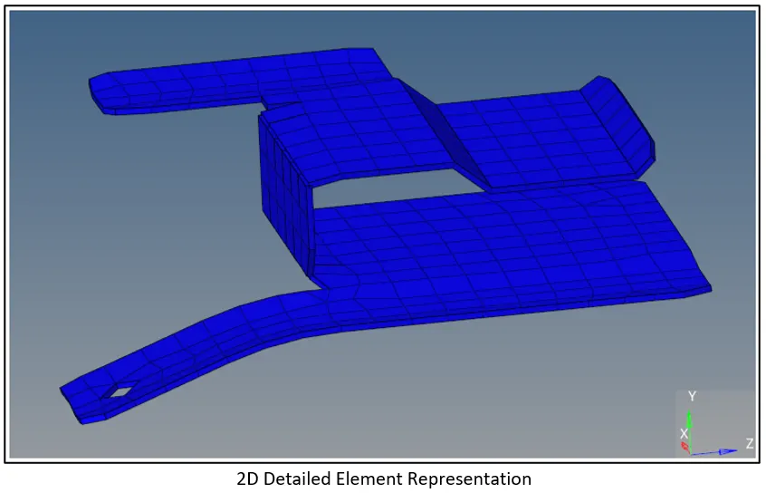
- Elements have been moved to a new component named “component1”
- New generic property has been created named “property comp 1”, alongside assigning thickness to shell elements equal to parent geometry thickness i.e. 91mm
- property comp 1 is assigned to component1
-------------------------------------------------------------------------------------------------------------------------------------------------------------------------------------
Model 2- mid surfacing, 2Dmeshing
Model Provided
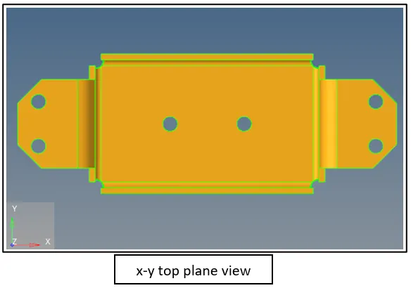
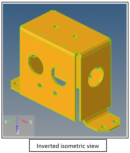
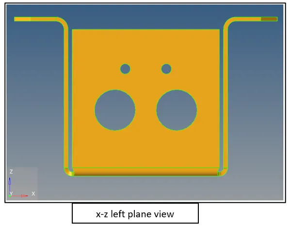
Mid surface extraction(Model 2)
- Change the method of mid surface extraction to skin offset
(Geometry>>midsurface>>extraction options>>skin offset)
Meshing Model 2
Additional meshing tools used:
- Reflect
- Ruled
- position
Quality criteria:
- min element size= 5mm
- max element size= 7mm
- Target element size= 5mm
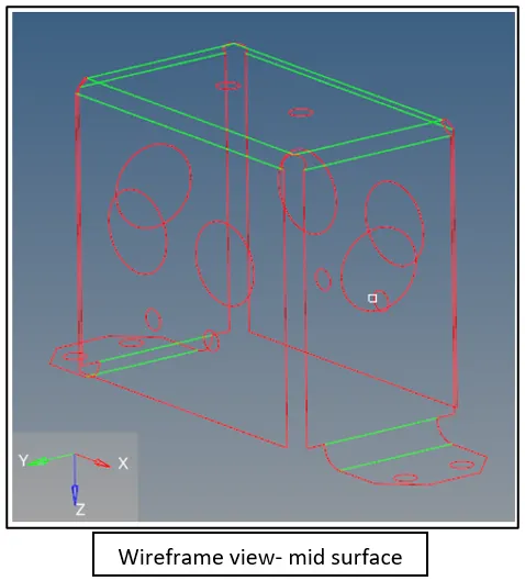
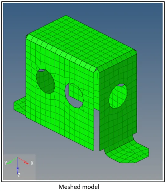
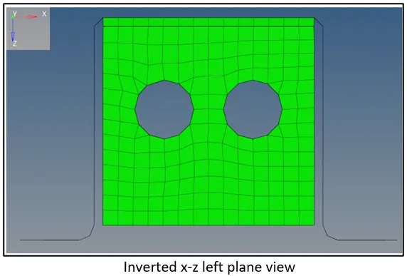
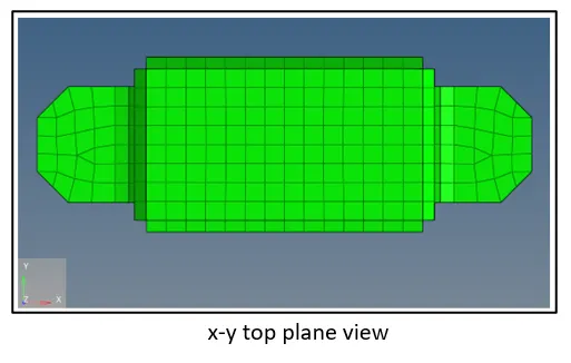
Note: While meshing strictly only length quality criteria mentioned above is followed
Quality check:
(2D>>Quality index)
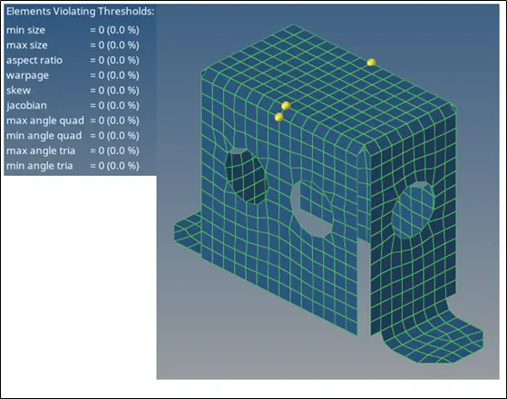
- It can be seen no element is failing under the given length quality criteria i.e. no element is violating the min and max size thresholds
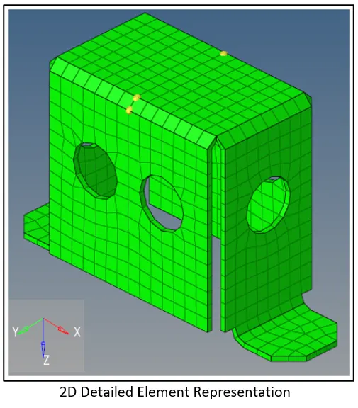
Organizing elements & assigning thickness by creating a generic property(Model-2)
- Elements are organized and moved to a new component
- The new component is assigned a property
- Solver Keyword is given to be PSHELL
- The thickness, T= 2mm(from parent geometry)
-----------------------------------------------------------------------------------------------------------------------------------------------------------------------------------------------
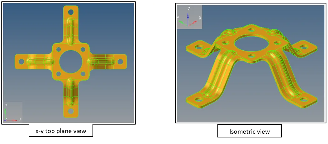
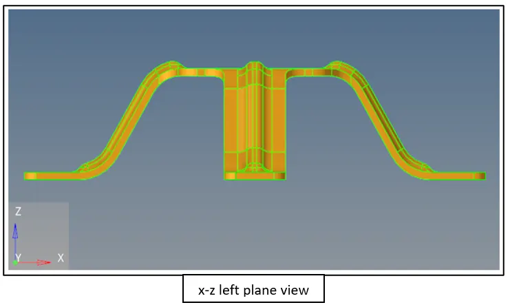
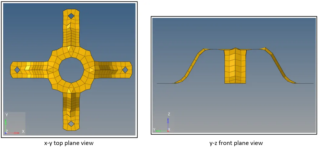
Model 3- mid surfacing, 2D meshing
Model Provided
Mid surface Extraction(Model 3)
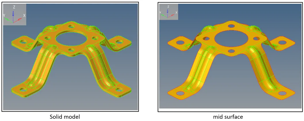
Geometry editing of mid surface:
- To improve the mesh flow the geometry edges which are too close to each other are toggled using tolerance 0.010mm
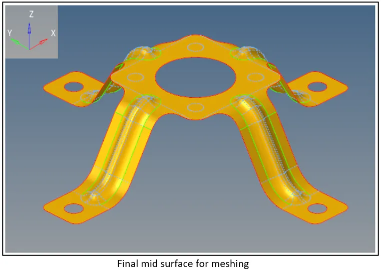
- Holes having diameter less than 6mm are ignored using filler surface as shown below
Edge toggle operation
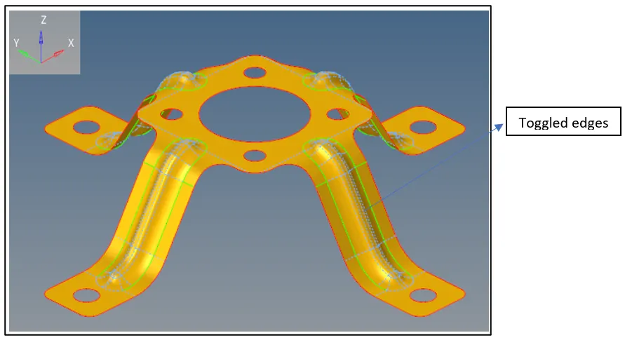
Surface fill operation
Meshing Model 3
Quality Criteria:
- Min element size= 3.5mm
- Max element size= 7mm
Target element size= 5mm
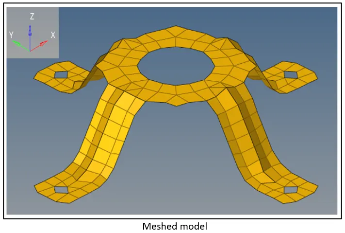
Quality check:
(2D>>Quality index)
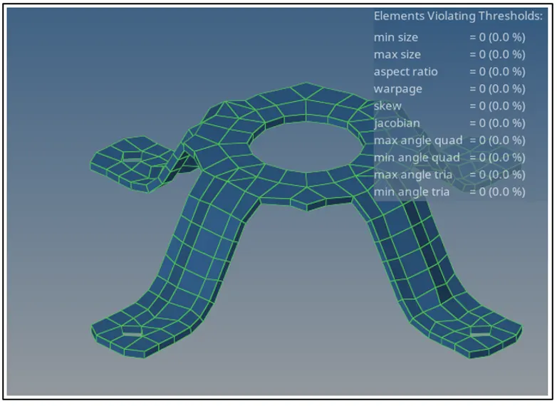
- It can be seen no element is failing under the given length quality criteria i.e. no element is violating the min and max size thresholds
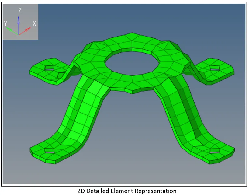
Organizing elements & assigning thickness by creating a generic property(Model-3)
- Solver keyword is set to PSHELL
- Thickness, T= 805mm(from parent geometry)
Conclusion
- Successfully performed various geometry clean-up operations along with extracting mid surfaces of given models with appropriate extracting options and performing 2D meshing to fit the provided quality criteria
Problems encountered and way to overcome them
- Mesh around a hole not regular: Usage of 4 elements to capture the small holes and even number of elements around bigger holes
- Irregular mesh due to various edges present in proximity: Use of toggle feature with appropriate tolerance
- Elements failing under given quality criteria: use of element clean-up operation as well as optimizing elements and manually moving nodes to fit the quality criteria
Limitations
- Mesh not capturing model geometry properly: Use of smaller target element size
- Holes which are not captured well: This can be sorted by using increasing the number of elements to a greater value(preferably even) or usage of washer-split