To carry out 3D meshing for the given models with Tetra Mesh and hex mesh and also to solve problems given regarding RADIOSS
Aim: To create 1D elements to connect two surfaces, perform 3D meshing for the given models and write the procedure for the same
Objective of project:
- To carry out 3D meshing using various methods of converting 2D mesh to 3D under given quality criteria for 2D elements
- To demonstrate connection of two surfaces through 1D elements
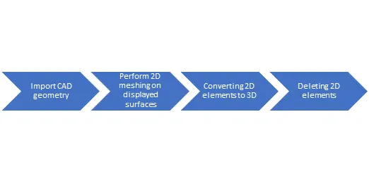
Workflow
1D- Elements
These elements essentially have 2 nodes, also these are not rigid bodies which means these 2 nodes can have relative motion between themselves
The following are some types of 1D elements we come across:
- CROD: These are also called TRUSS elements. These asks for only 2 nodes which implies there is no frame of reference as such thus, these elements can undergo axial load(compression & tension) i.e. there is no bending in case of RODs
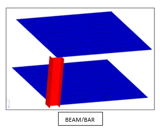
- CBAR & CBEAMS: These elements elements take care of the bending aspect too. A CBAR element is a kind of simplified CBEAM element and should be used whenever the cross-section of the structure and it’s properties are constant and symmetrical
The CBAR elements require that it’s neutral axis and shear center coincide. Due to this CBAR elements are not useful to model structures that may warp, such as open channels. This limitation is not present in CBEAM elements
Rigids
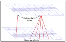
- Rigids- RBE2: Rigid link to transfer motion from the independent node to the dependent nodes. Whatever is the load at the master node(independent node), identical loads will be applied to all the slave nodes(dependent nodes).
The master node is calculated by weighted center of mass for all the selected dependent nodes.
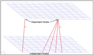
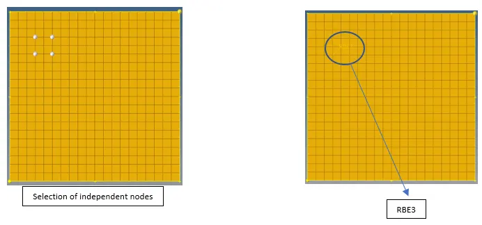
RBE3: This is a rigid link to distribute loads and will not induce stiffness. Typically used to distribute loads applied on the dependent node amongst the selected independent nodes.
The distribution is basically based on the distance/ closeness of the independent node from the dependent node on which the load is applied. Closer the independent node more fraction of load would be assigned to it.
Connectors
- These are geometric entities that define connection between other entities
- Connectors allow for rapid and easy creation of FE welds, bolts, adhesives, etc
Following are some types of connectors:
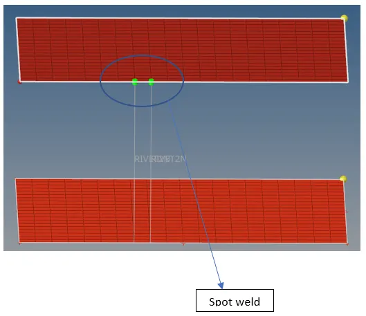
- Spot: Used for connections at a point- spot welds, rivets, etc
- Bolt: For connections at hole locations
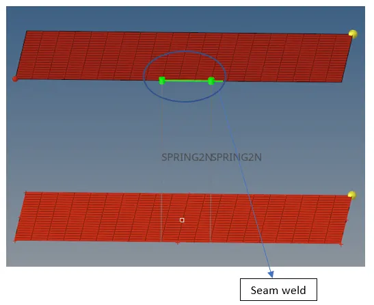
- Seam: Used for connections along a length-seam welds. Connects geometry only.
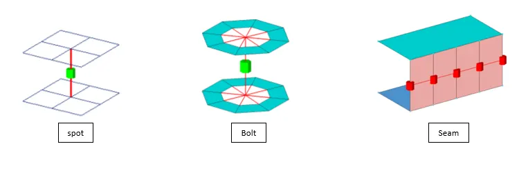
1D Element Demonstration

surfaces provided:
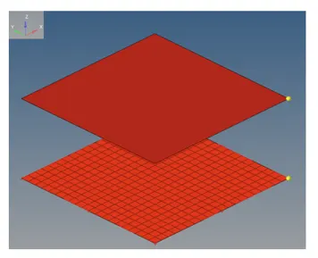
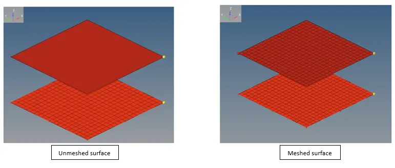
2D meshing:
- The mesh on the bottom surface is duplicated and then projected on the above surface as both the surfaces are identical
- Project tool is using keys Shift+F7 and then selecting desired elements to be projected on the selected surface
Rigids
(1D>>Rigids)
Set the following fields as shown:
Primary node: calculate node
Nodes: multiple nodes
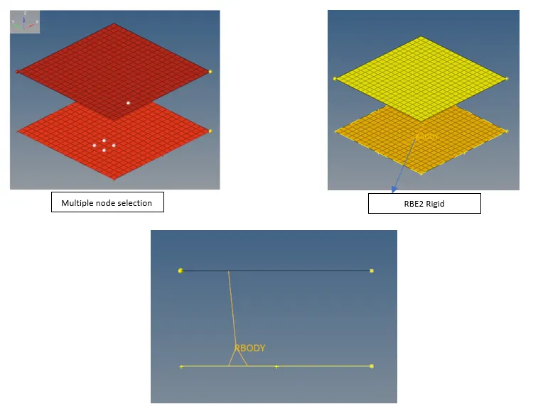
RBE3
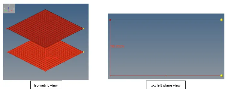
Rod element(Truss element)
(1D>>Rods)
- This requires selection of 2 nodes
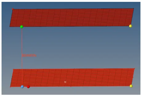
Bar element
- This asks for 2 nodes to be selected and another node to decide the x-y plane
Spring element
- These are of two types- two noded spring & three noded spring
3 noded spring asks for two nodes input and one node input for the orientation just like beam/bar element
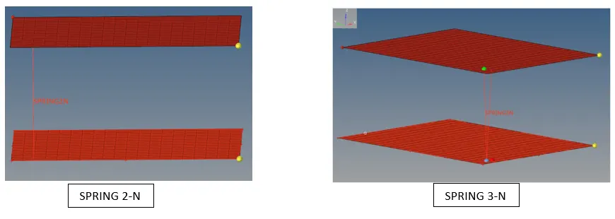
Note: Usage of SPRING 3-N element is mostly restricted to the design of vehicle seat belts only, while spring 2-N is most used
Connectors
Seam
Spot weld
3D Meshing
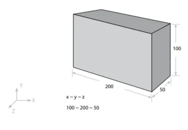
3D meshing is used when all the three dimensions are comparable
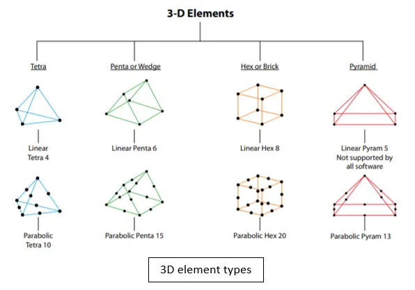
Element shape: Tetra, Penta, hex, pyramid
Additional data from user: none
Element type: Solid
Practical applications: gear box, engine block, crankshaft, etc.
DOFs of solid elements: 2D thin shell and 1D beam elements supports 6DOFs, but all solid elements have only 3 translational DOFs
Tetra meshing techniques
There are essentially two methods of tetra meshing:
- Automatic Meshing: This approach is limited to simple geometries and the pre-requisite is a spick and span CAD model. The user selects the volume and software carries out the meshing automatically as per user specified element length and quality criteria
Advantage: very quick
Disadvantage: Generates very high number of nodes and elements, no control over mesh flow
- 2D(Tria) to 3D(Tetra): This is the most common method. Quad or Tria meshing is carried out on all the outer surfaces of the geometry. During Tetra meshing the quads are automatically split into Trias, which then serve as the basis of the tetra elements
Generation of 3D elements using Hypermesh
Tetra elements
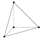
These are solid elements extracted from 2D tria elements, they have a tetrahedral shape as follows:
Tetra mesh panel
Using this panel, Tetra elements can be automatically created. This panel allows you to fill an enclosed volume with first or second order tetrahedral elements
Some sub-panels of tetra meshing are:
- Tetra mesh: Allows to fill an arbitrary volume, defined by it’s surface using tria/quad elements, with tetrahedral elements
- Volume tetra: Given a set of surfaces representing a closed volume, this meshing option generates a shell mesh and fills the enclosed volume with solid elements
Hexa and Penta elements
Hexahedral(hexa or brick) elements are solid elements extracted from 2D quad elements. Pentahedral(Penta) elements on the other hand have been extracted from 2D Tria elements. There shapes are as shown below:
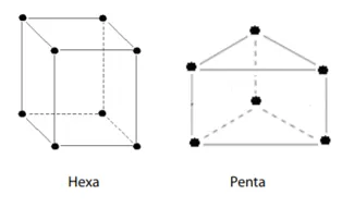
Pentas and Hexas can be built using any of the following options:
- Drag: Drags a group of 2 dimensional elements along a vector to create solids
- Linear solid: creates solid elements between 2 dimensional elements
- Solid map: Builds solid elements between nodes, lines and surfaces(explained below)
- Elem offset: Creates solid elements by offsetting a group of 2D elements normal to the surface formed by the 2D elements group
- Spin: Spins a group of 2D elements about a vector to create solid elements
Solid Map meshing
In solid meshing, the ability to be meshed is referred as mappability. Mappability is directional, it is done by putting a surface mesh on one face of a solid then extending that mesh along a vector through the solid volume.
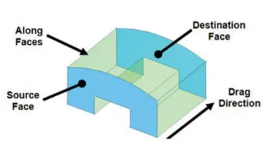
Note: In the above figure, source and destination face are identical however, this is not an essential requirement. The source and destination can be of drastically different shapes and need not lie directly opposite to each other.
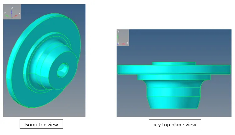
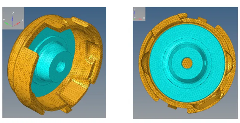
3D meshing- Housing
Model Provided
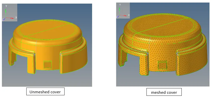
Cover
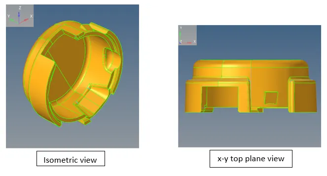
Hub
Quality Criteria for 2D & 3D mesh:
- Lmax =7mm, Lmin = 3.5mm
- Target element size= 5mm
- Aspect= 5
- Skew= 60
- Jacobian= 0.5
- Warpage= 15
- Tria angles= 20 to 120
- Quad angles= 40 to 140
- Hex element target size= 10mm
- Tet collapse= 0.15
2D element mesh to 3D element mesh
Cover 2D mesh
2D element Quality check:
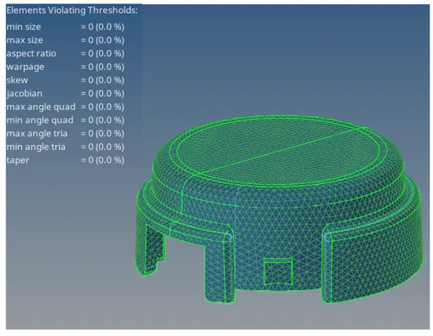
- It can be seen no Tria element is violating the failure thresholds, which is a green signal to convert the elements to 3D Tetra
Cover 2D to 3D element conversion
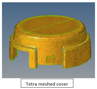
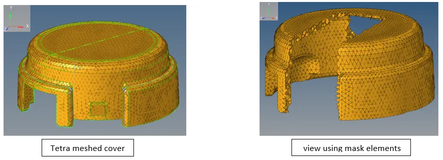
Now, checking for elements failed under Tet collapse parameter(Tool>>check elems>>3D>>Tet collapse) reveals that in the above Tetra meshed cover 117 elements are failed(this message comes in the left bottom of screen)
To fix the elements failing under Tet collapse, we change the Tetramesh parameters as shown below in 3D>>Tetramesh>>Tetramesh parameters:

Now the model is re-meshed by Tetra re-mesh>>selecting all 3D elements>>Re-mesh
Finally we get the Tetra meshed cover which has 0 elements failing under Tet collapse
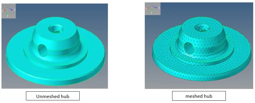
Hub 2D mesh
2D element Quality check:
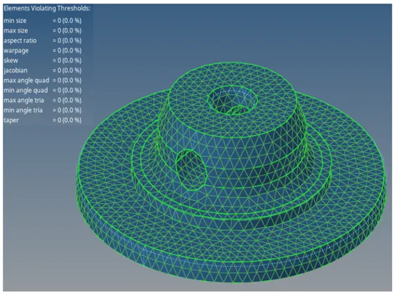
- No Tria element is crossing the failure threshold
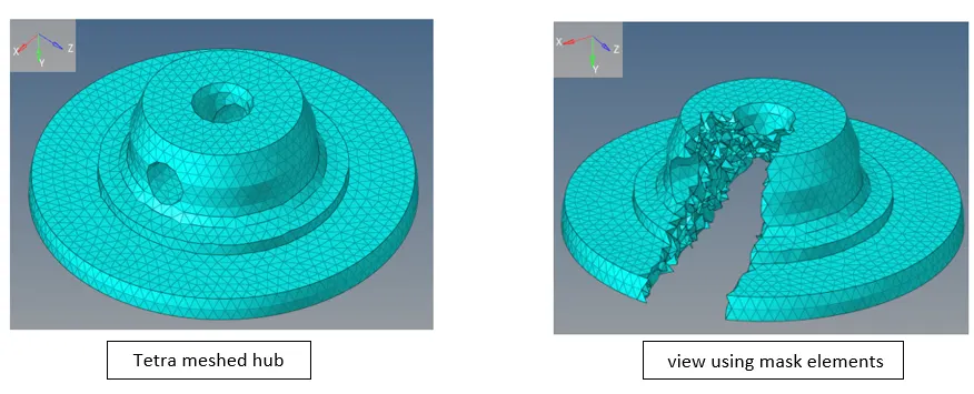
Hub 2D to 3D element conversion
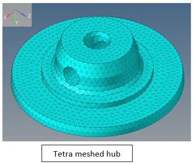
In the above tetra meshed hub 52 elements are failing. To fix these we change the tetra mesh parameters as follows:

Re-meshing using above parameters yields tetra meshed hub in which zero elements fail under tet collapse criteria
Graphics of assembled tetra meshed housing
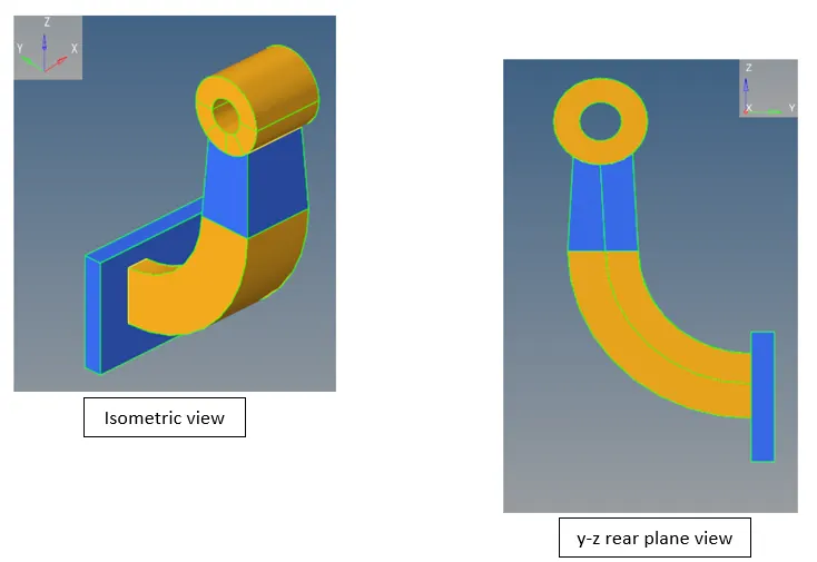
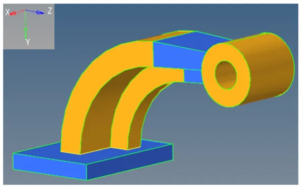
3D Meshing- Arm Bracket
Model Provided
Base 3D meshing using elem offset
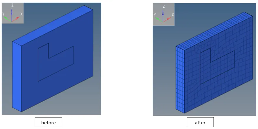
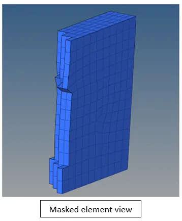
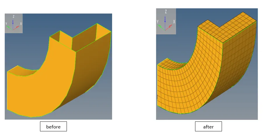
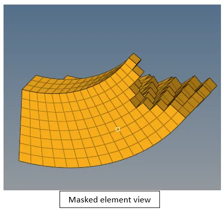
Curve arm 3D meshing using spin feature
Tapered arm 3D meshing using Linear solids
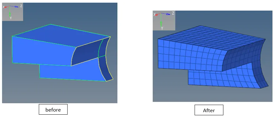
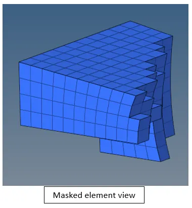
Boss 3D meshing using solid map
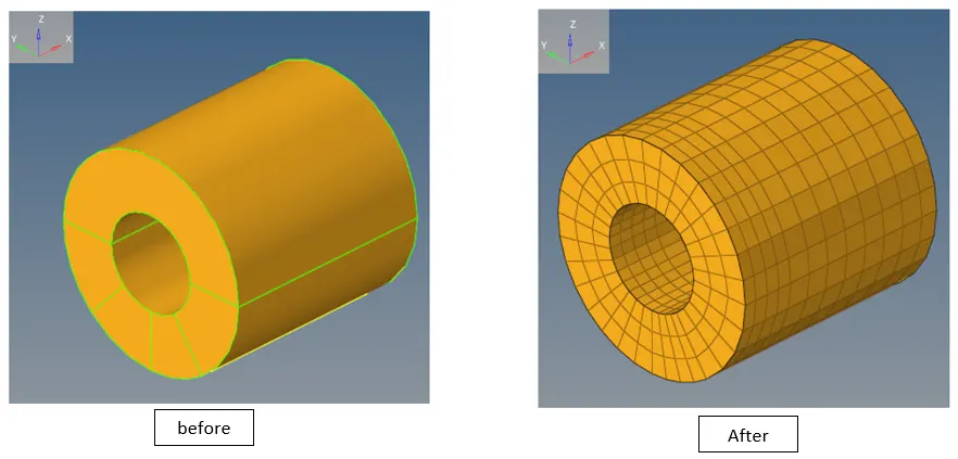

Assembled 3D mesh of Arm Bracket
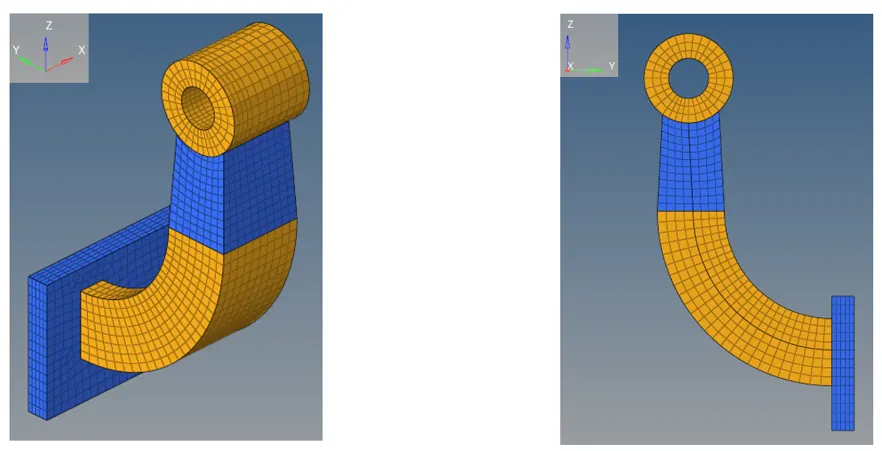
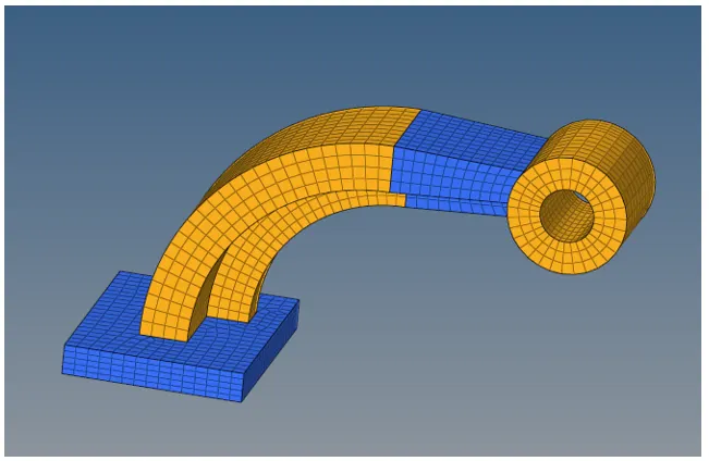
Note: The above 3D meshing procedures for arm bracket produces directly 3D hexahedral elements, except for elem offset method in which first a 2D mesh panel was created, which in turn was given offset to produce 3D hexahedral elements after which these 2D elements were deleted(Quad 4 elements)
Question and Answers
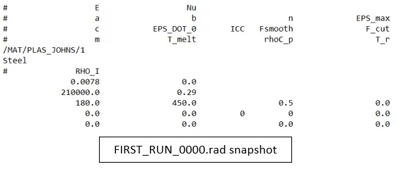
Question 1: Check the material properties of the rail component and calculate the speed of sound in steel rail=_______
Answer 1: c =
Where c= speed of sound
E= Modulus of Elasticity
ρ= Density(Rho)
From above snapshot the values of E & ρ can be construed
Therefore, E= 210000 MPa or 210GPa and ρ= 0.0078 g/mm3
Thus, c = = 5188.74 m/s
Question 2: The length of the rail is about 1000 mm.calculate the time takes for a shock wave to travel from one end of the rail to the other.
Answer 2: t = d/s
Where t= time taken
d= distance = 1 m
s= speed = 5188.74 m/s
Thus, t = 1/5188.74 = 0.192 ms
Question 3: Time for sound to travel length of rail=______
Answer 3: Time for sound to travel length of rail = 0.192 ms
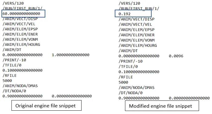
Question 4: To edit engine file so that the stress wave can be monitored, moving from one end of the rail to the other during impact.
Answer 4: This is done by specifying a termination time equal to the time it takes for the sound to travel the length of the rail
Thus termination time = 0.192 ms
Question 5: Set the frequency of animation output to a time that will give 20 animation steps
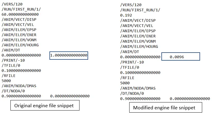
Answer 5: To do this we divide the time taken calculated above by 20 i.e. 0.192/20 = 0.0096
Now we change the TFREQ number under /ANIM/DT in the engine file as shown below
Result
- As per material properties of the rail component the speed of sound comes out to be 74 m/s
- The time taken for a shock a wave to travel from one end of the rail to other is 192 ms
- Termination time is 192 ms
- Frequency of animation that will give 20 animation steps is 0.0096
Conclusion
- Successfully performed 3D meshing operations on the given models under the specified quality criteria and checked for Tet Collapse, demonstrated 1D elements-rigids & connectors
Problems encountered and ways to overcome them
- 3D mesh elements not able to capture geometry sharp turns: To fix this problem, mesh quality criteria can be changed and element size can be decreased further
- Elements failing due to excessive closeness of edges: To account for this problem, we use toggle feature in geometry edit panel to toggle the required edges and portray as if they were not there
- Elements failing under given Quality criteria: To fix this, element clean-up and optimization features can be used
Limitations
- Mesh not capturing geometry properly: Use of smaller target element size
- Holes not capturing well: This can be sorted by using features such as proximity to put more number of elements along the hole surface