Assignment 2-RADIOSS Engine File Editing & 3D Meshing Challenge
Assignment 2: Crashworthiness Analysis using HyperMesh and Radioss
RADIOSS ENGINE FILE EDITING, TETRA MESHING AND HEXA MESHING IN HYPERMESH
AIM:
- To study the Starter file and Engine file in RADIOSS user profile
- Change the parameters according to the requirement in Starter and Engine files
- Create Tetra Mesh for housing component and solve Tet-Collapse
- Create Hexa Mesh for Arm Bracket
Objective:
- Check the material properties of the rail component and calculate the speed of sound in steel rail=_______
- The length of the rail is about 1000 mm. calculate the time takes for a shock wave to travel from one end of the rail to the other.
- Time for sound to travel length of rail=______
- Edit the engine file so that the stress wave can be monitored, moving from one end of the rail to the other during impact -this will require a termination time equal to the time it takes for the sound to travel the length of the rail (set on/RUN card)
- Set the frequency of animation output to a time that will give 20 animation steps(/ANIM/DT)
- Change /print -10
-
3d meshing tetra mesh and hex mesh
- Repeat class examples and, maintain the quality.
- Target tet size=5mm, hex size=10mm, tet collapse=0.15
Procedure:
Importing RAD file (FIRST_RUN_0000) in HYPERMESH
- Import “. rad” file as shown below in RADIOSS user profile
- Browse the required file and click on import
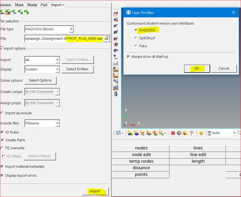
Importing .rad file in radioss user profile
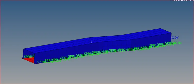
Imported model using .rad file
Objective1: Check the material properties of the rail component and calculate the speed of sound in steel rail
- Checking the material properties of the rail component
- Go to model block and in properties you can see the required values
- We can also open "FIRST_RUN_0000.rad " starter file in notepad and find the same values. I have highlighted them below
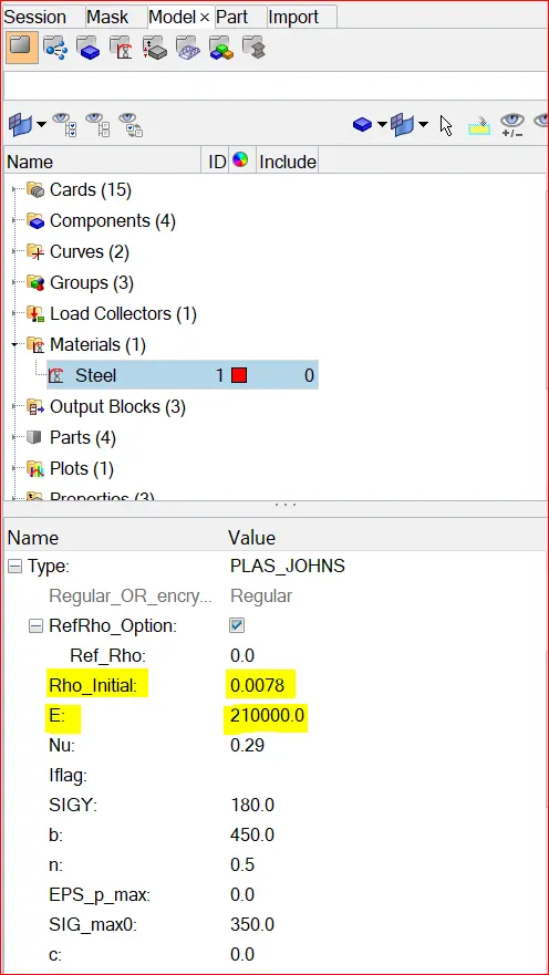
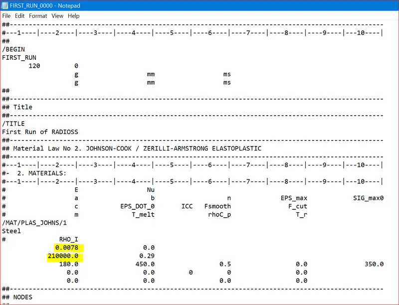
Properties of rail component Properties of rail in .rad file
- Here Rho_initial = 0.0078 is the initial density and E= 210000 is the young’s modulus
- Speed of sound in the material (c) = c = `√(E/ρ)`
- Therefore, speed of sound (c) = `√(210000/0.0078)` = 5188.745 m/s
Objective 2: The length of the rail is about 1000 mm. calculate the time takes for a shock wave to travel from one end of the rail to the other.
- Shock wave travels at the speed of sound.
- Therefore, shock wave speed = speed of sound = 5188.745 m/s
- Here distance of the rail d = 1000mm
- time (t) = `((Distance)/(Speed. of . shockwave))`
- So, time taken for a shock wave to travel from one end of the rail to the other end = `(1000/5188.745)` = 0.192725ms
Objective 3: Time for sound to travel the length of rail = 0.192725 ms
Objective 4: Edit the engine file so that the stress wave can be monitored, moving from one end of the rail to the other during impact -this will require a termination time equal to the time it takes for the sound to travel the length of the rail (set on/RUN card)
- Initially, the end time is 60ms. We need to change that to 0.192725ms
- You can edit it in Model deck >> Cards >> ENG_RUN >> Tstop
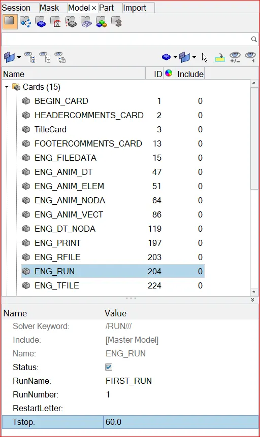
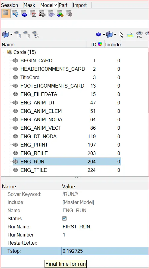
Initial time for run value Edited time for run value
- You can also edit the Tstop value in engine “FIRST_RUN_0001” .rad file
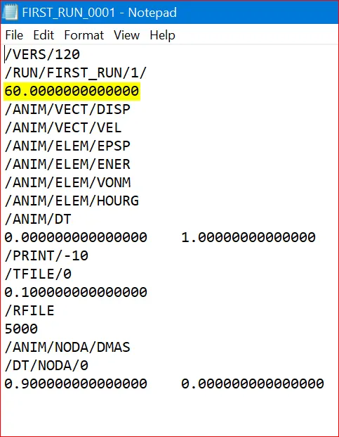
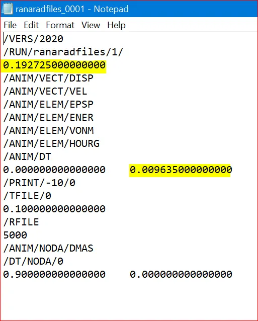
Initial time for run value Edited time for run value
Objective 5: Set the frequency of animation output to a time that will give 20 animation steps(/ANIM/DT)
- frequency = `(Time)/(no .of. revolutions)` = `0.1927/20` = 0.009635
- Similarly, we can edit this in cards >> ENGINE_ANIM_DT or in (.rad file) FIRST_RUN_0001.
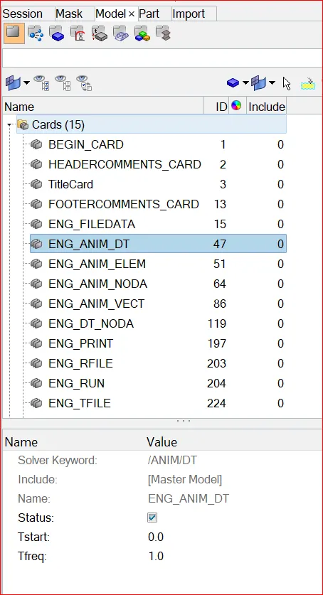
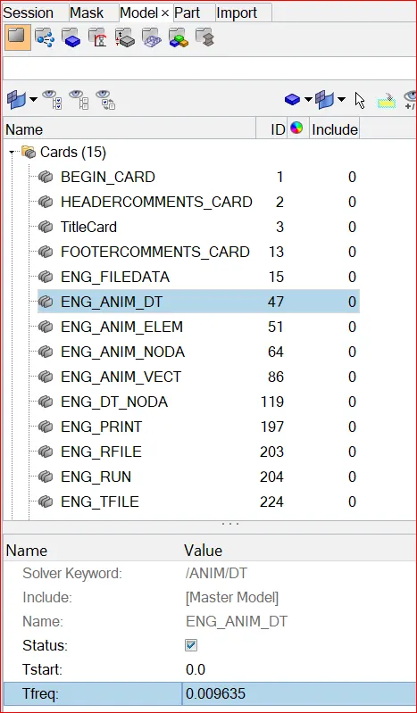
Initial frequency Edited frequency
Objective 6: Change /print -10
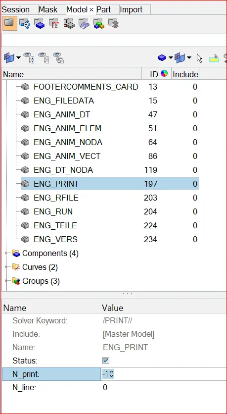
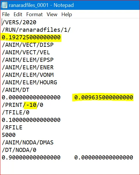
Edited Print Value
Objective 7: 3D meshing tetra mesh generation for Housing Component
There are three methods to generate Tetra Meshing as stated below:
- Using the Volume Tetra option
- Using the Quick Tetra Mesh, from the Utility panel.
- Converting 2D tria surface mesh into 3D hexa mesh
- If you want to explore 2 & 3 methods. Please check out my other project in the link below.
- https://skill-lync.com/projects/week-8-3d-tetra-meshing-challenge-69
1. Volume Tetra
- Go to 3D >> tetra mesh >> Volume tetra
- Tick curvature and proximity options for better feature capturing of mesh.
- Select the required solids or surfaces of each component individually
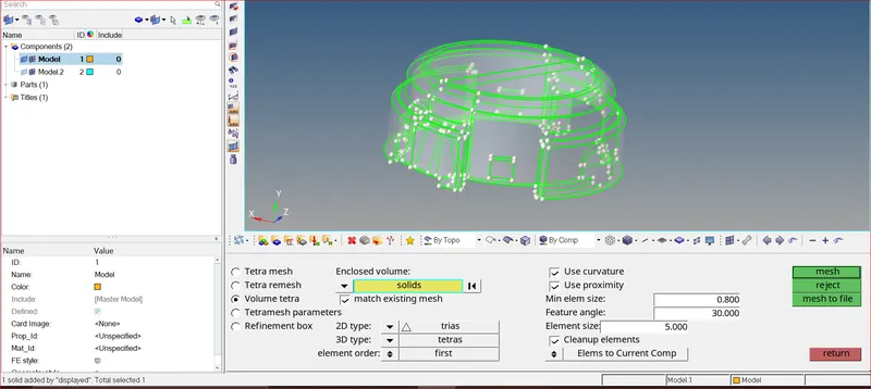
Selecting solid using volume tetra option
- Volume tetra mesh is generated successfully, I have masked some elements in order to check the mesh which is generated
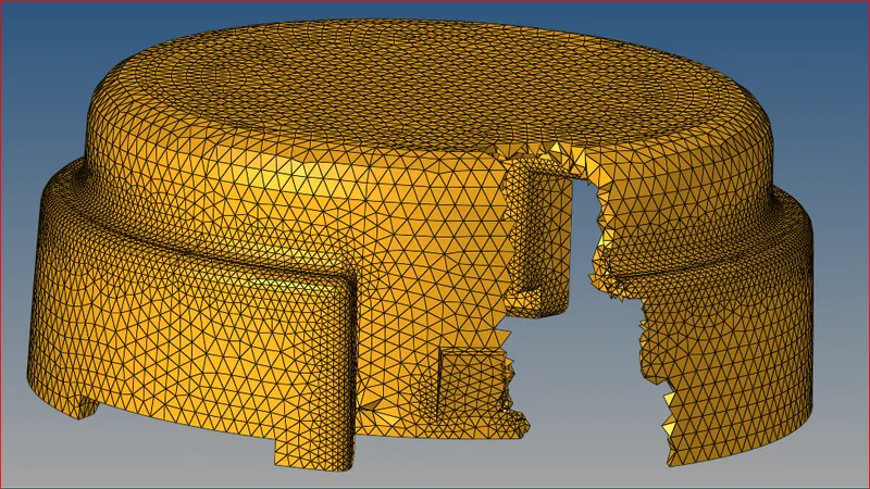
Volume mesh generated successfully
- Similarly do the same process for the other solid to generate volume tetra mesh
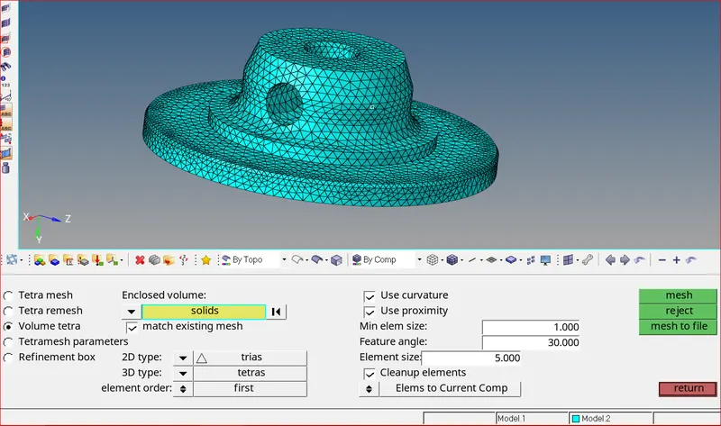
Volume mesh generated successfully
Tet Collapse
- Tet collapse is one of the quality parameters, which will be checked while generating Tetrahedral elements.
- It can be calculated by measuring the distance of a node from the opposite face, then each of the four values will be divided by the square root of the opposite face’s area.
- The minimum of four resulting values is then normalized by dividing it by 1.24.
- Generally, tet collapse can be calculated by the formula = Min of`((h)/(√(A))) ÷ 1.24`
- In that formula, “h” represents the Height, between the Node (N1) and the opposite face of the Triangle. “A” represents the Area of Opposite Face (area of the Triangle)
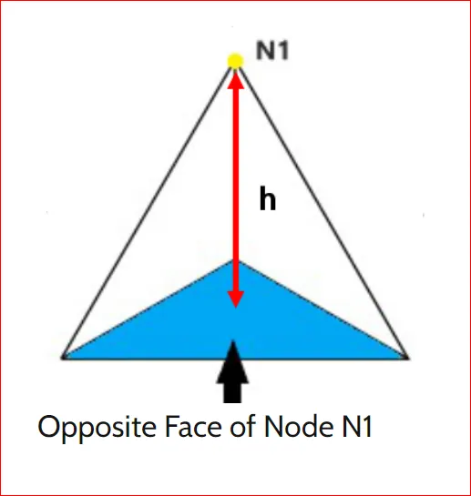
Solving Tet collapse
Tet collapse can be solved in 3 ways.
- Using Tetra Remesh option
- Solving Tet Collapses Manually using Translate option
- Using FIX 3D elements option
- If you want to explore 2 & 3 methods. Please check out my other project in the link below.
- https://skill-lync.com/projects/week-8-3d-tetra-meshing-challenge-69
Using Remesh
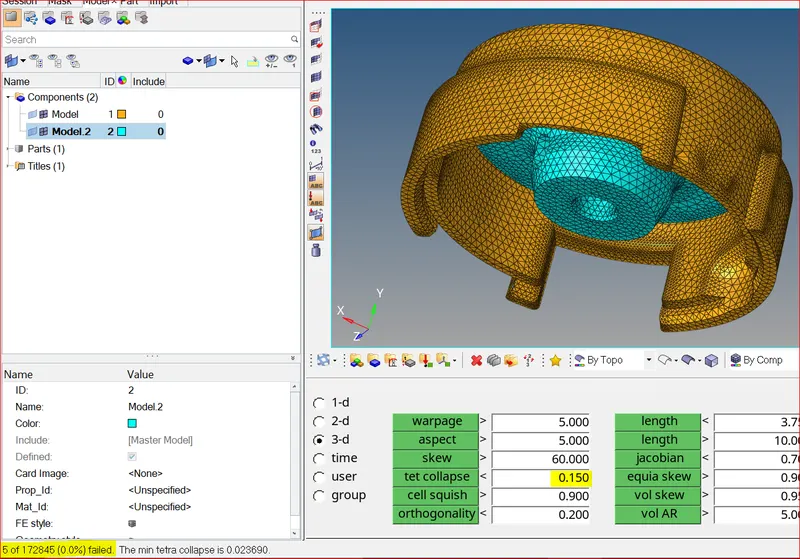
Checking Elements for Tet collapse
- Now, click save failed and retrieve the failed elements in mask option
- While remeshing use the neighbouring elements also
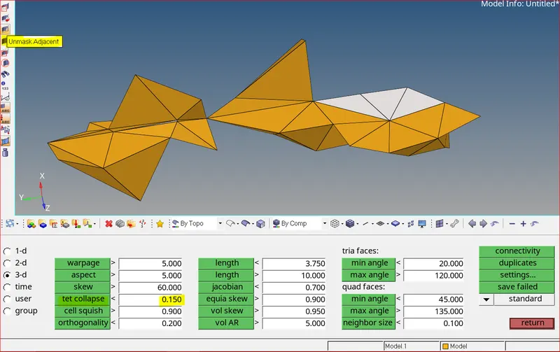
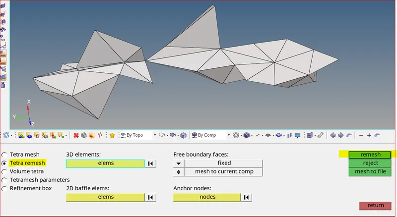
Failed elements along with adjacent elements Remeshing Elements
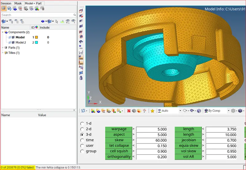
All tet collapse are solved
Objective 8: HEXA mesh generation for Arm Bracket
- The meshing of any component using Hexa elements is complicated as compared to tetra elements.
- In this challenge, the arm bracket must be meshed using only Hexa or brick elements
- I have divided the given geometry into 4 components inorder to maintain the mesh connectivity
- First create 2D quad mesh on the base model’s top surface
- Remove all the trias and rotating quads. Use element size as 10
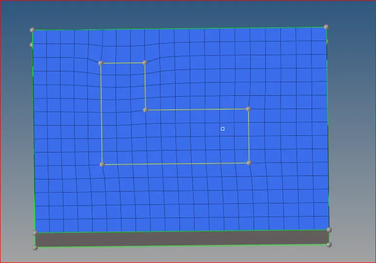
2D quad mesh on top surface
Creating Solid Layers
- Create 3D brick or Hexa elements from 2D quad mesh using 3D >> element offset >> solid layers as shown below
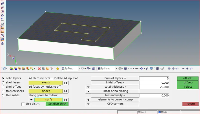
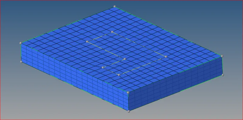
Converting 2D quad elements into brick elements Hexa mesh created successfully for base component
- Now create a temporary node using geometry >> nodes >> arc center as shown below
- This node will act as a base node for spinning elements onto the 2nd U-shaped component
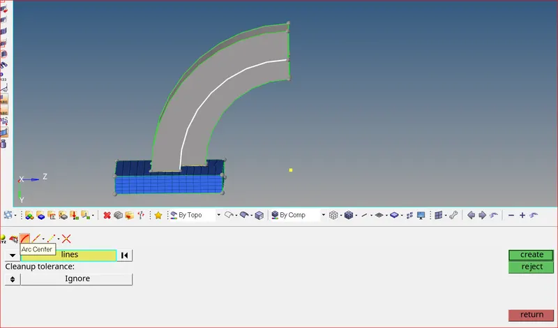
Node created for Arc centre
Spinning Elements
- Use 3D >> spin >> spin elements. Select the required elements for spinning. Give angle as 90, spin layers as 25 and also select the axis for rotation and base node as shown below
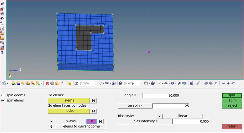
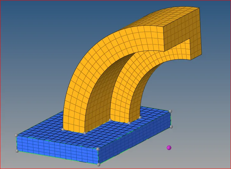
Selecting elements for rotation Spinning of elements is successful
- Now, create surface mesh on the end surface of the 2nd component and 3rd component
- 2D quad elements created should match both the surfaces. Our plan is to create 3D hexa mesh between two 2D shell layers
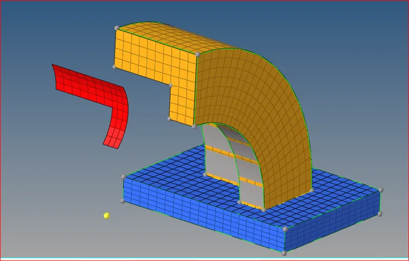
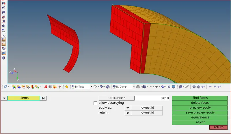
2D shell elements created at the end of 3rd component 2D shell elements created at the end of 2rd component
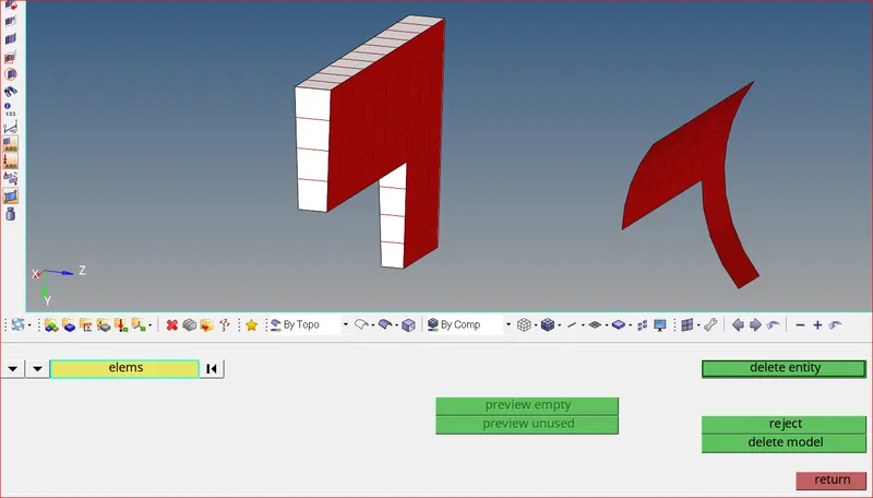
Deleting unnecessary 2D elements
Solid Mapping Elements
- Now, create 3D hexa mesh between these two 2D element layers using using 3D >> solid map >> general, selecting the elements to drag and elements to match and all required options as shown below
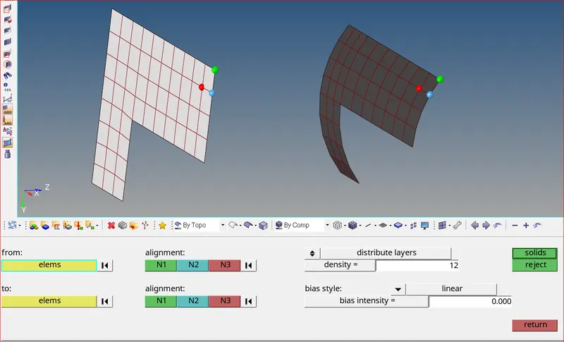
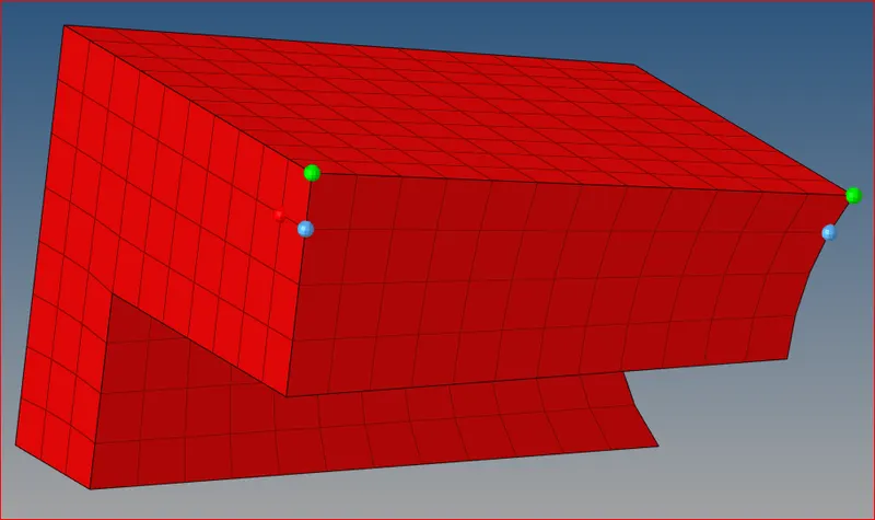
Selecting elements and nodes for solid mapping Hexa mesh successfully generated for 3rd component
- Similarly create 2D quad mesh on the surface of the 4th Be careful because the elements created should match the elements of 3rd component as shown below
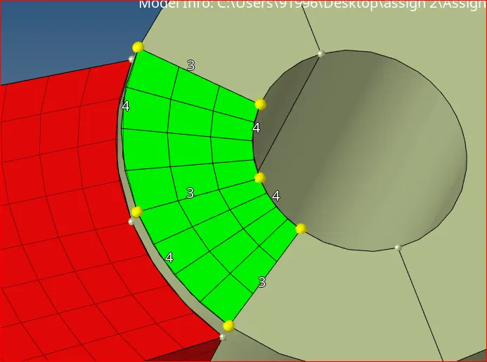
2D surface mesh of 4th component
- Now project a point on to the surface below. This will act as a end node while solid mapping. Use tools >> project
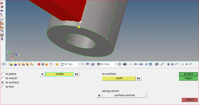
Point projected on to the surface
Dragging Elements
- Use 3D >> solid map >> line drag option. Select elements to drag and node path as shown below
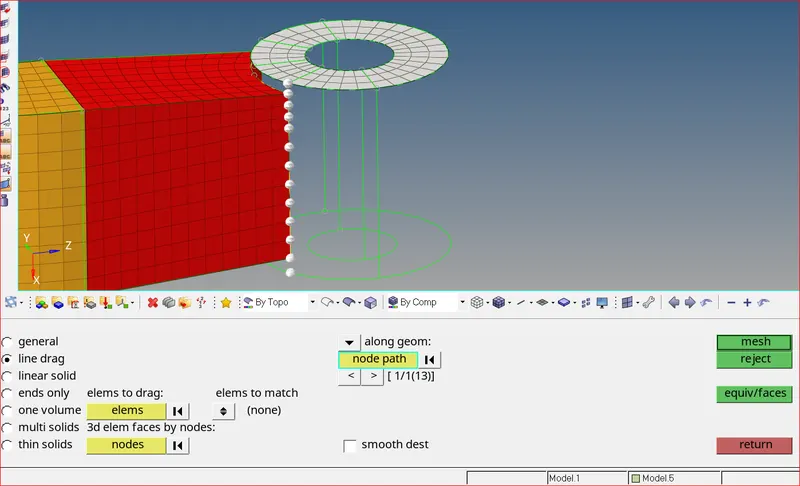
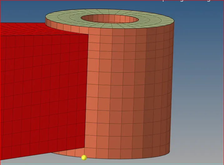
Selecting elements for dragging Elements dragged successfully
Deleting 2D quad elements
- Delete all the 2D quad elements which we created on the surfaces of components
- Use >> delete >> elements >> by config >> quad4 >> select entities >> delete entity
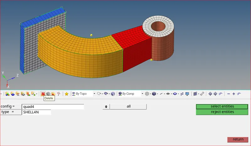
Deleting Quad4 elements
- If you mask some elements on each component, you can see that brick elements or hexa mesh is generated successfully for Arm Bracket
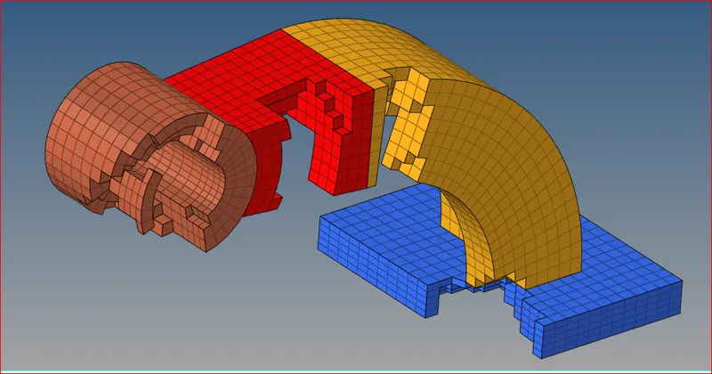
Elements Masked on each component
Outcome and mesh connectivity
- Connect the mesh is very important. Connecting mesh will give us better load transformation while simulation
- There will be no use of the mesh if you do not connect elements properly. You can see in the below picture that the mesh is connected properly.
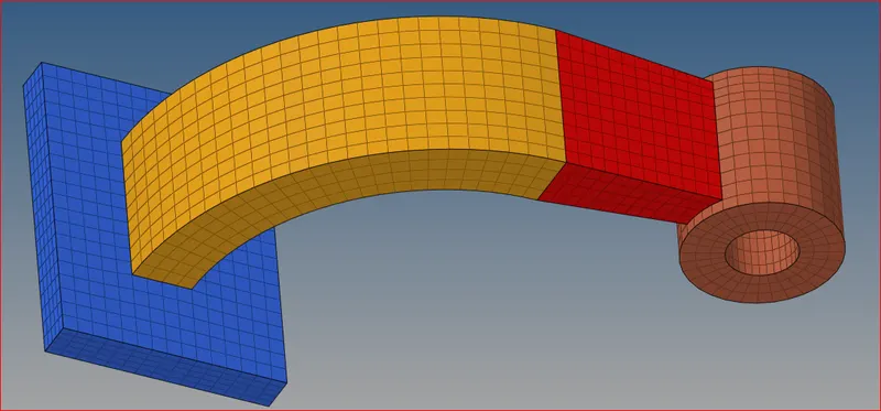
Hexa Meshing is successfully done for the Arm Bracket
Learning Outcomes:
- All the calculations are made according to the question
- Edited Engine file according to the calculations made
- Tetra mesh is generated successfully for the housing component without any tet collapse
- Hexa mesh is generated for Arm Bracket with perfect element connectivity
Conclusion:
After completion, calculations are done successfully and edited them in engine file. Tetra and hexa mesh is generated to the required components. All the processes are explained in detail.