Advanced Sheet Metal Design Using NX Cad Challenge_7_ Metal bracket-II
- TITLE
Create ‘Bracket’ from 2D drawing.
- OBJECTIVE
To create a bracket in the sheet metal workbench of NX from the provided 2D drawing.
- INTRODUCTION
NX Cad
NX formerly known as unigraphics is one of the world’s most advanced and tightly integrated CAD/CAM/CAE product development solution. The software has powerful hybrid modeling capabilities by integrating constraint based feature modeling and explicit geometric modeling.
Sheet Metal (SM)
Sheet metal is available in flat pieces or coiled strips that originate from many different metals such as aluminum, brass, copper, steel, tin, nickel, or titanium. It is formed into thin, flat pieces and is one of the most basic materials used in metalworking thanks to its malleable properties that enable it to be cut and bent into a multitude of shapes. Perhaps without realizing it, we are surrounded by a myriad of common objects that are fabricated from sheet metal: from automotive bodies to aerospace fuselages and wings, up to medical tables, sinks, roofs of buildings, and machinery.
There is a significant variation in the thickness of sheet metal; the thinnest sheets are referred to as foil or leaf, and pieces with a thickness greater than 6 mm (0.25 in) are considered plate.
Gussets
Gussets are used to strengthen a flange without the need for secondary processes such as welding.
A general guideline suggests that the width and depth of gusset at an angle of 45 degree is directly proportional to the radius and material thickness.
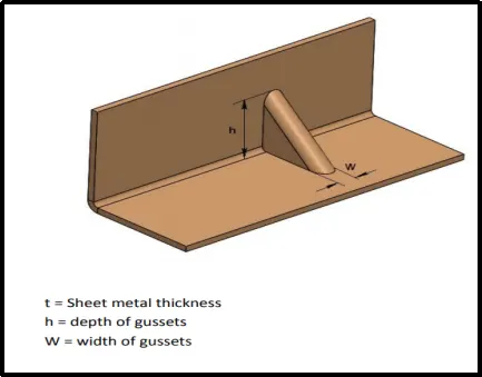
Minimum distance from hole to gusset
GA certain distance must be maintained between a hole and gusset to avoid metal deformation and fracturing.
It is recommended that minimum distance between hole edge to gusset should be at least eight times the material thickness.
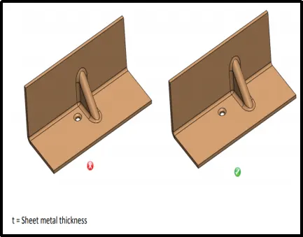
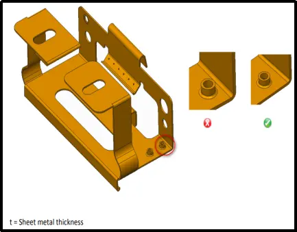
Minimum distance from extruded hole to part edge
Extruding metal is one of the most extreme pressure applications in press working and generates lot of friction and heat. If an extruded hole is too close to the part edge,it can lead to deformation or tearing of metal.
It is recommended that the minimum distance between the etruded holes to part edge should be atleast three times the thickness of sheet
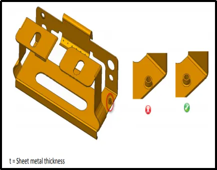
Minimum distance between extruded holes
Certain distance should be maintained between to extruded holes in sheet metal designs. If extruded holes are too close it can lead to metal deformation.
It Is recommended that the minimum distance between two extruded holes should be six times the thickness of sheet metal.
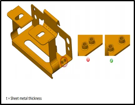
Minimum distance between extruded hole to bend
A certain distance must be maintained between extruded hole to bend to avoid metal deformation and fracturing.
It is recommended that the minimum distance between extruded hole and bend should be three times the thickness of sheet metal plus bend radius.
- DESIGN METHODOLOGY
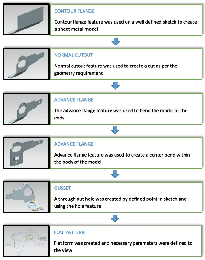
- DESCRIPTION
Contour Flange
Creates a base feature by extruding a sketch along a vector.
Advanced Flange
Adds a flange along an edge using a bend angle or a reference face.
Unbend
It flattens a bend and material adjacent to the bend
Rebend
It restores a bend
Break Corner
Rounds or chamfer a sharp corner of a tab or a flange
Hole
Adds a hole to one or more bodies in a part or assembly
Gusset
Creates a stiffening gusset on the part. This increase the strength of the sheet metal at the bend area.
Flat pattern
Creates a flat pattern feature from the formed sheet metal part
- IMAGES
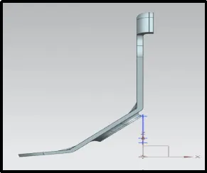
Front View
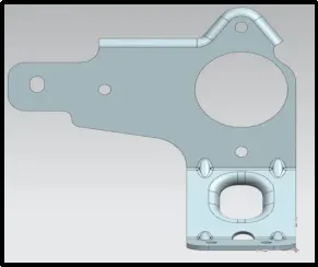
Side View
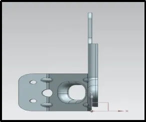
Top View
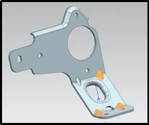
Isometric View
- CONCLUSION
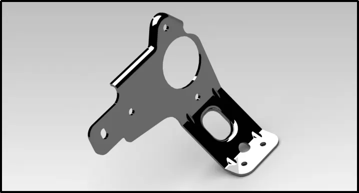
Thus, a bracket was created in the sheet metal workbench of NX from the 2D drawing
8. REFERENCE
- Important design guidelines for sheet metal - DFM Pro