Photo Realistic Rendering
Photo Realistic Rendering
Date : 12-03-2021
OBJECTIVE
Modeling, Assembly and Photo Realistic render of American Chopper
Objective of this project is to create part drawings, convert them into 3D models, assemble the created parts in Solid Works and giving it a photo realistic render using photo view 360 & SolidWork Visualize.
INTRODUCTION
Solid Works is a solid modeling CAD (Computer Aided Design) and CAE (Computer Aided Engineering) Software Published by Dassault Systems. It was developed by MIT graduate Jon Hirschtick and bought by Dassault Systems in 1997. Its a parametric modeling software in which you capture design intent using features and constraints.
DESIGN PROCESS
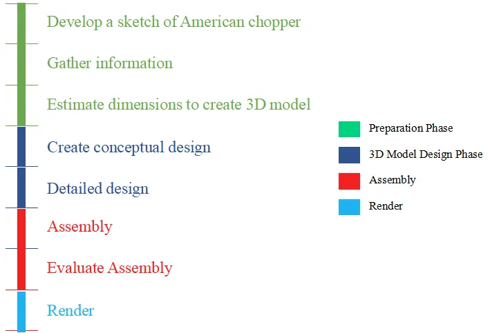
DESCRIPTION
Chopper is a custom motorcycle which emerged in California in the late 1950’s. They often use radically modified steering angles and lengthened front fork. The were initially built from original motor cycles by modifying/Chopping various parts, Thus the name chopper.
The American Chopper created in this project consists of 13 individual parts,namely:
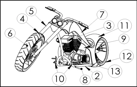
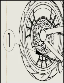
Fig A. Parts of American Chopper
|
Sno |
Description |
Purpose |
Material |
Quantity |
|
1 |
Chain |
Power Transmitting Unit, Gear box (output) to sprocket(rear wheel) |
Copper,Chrome |
1 No |
|
2 |
Chassis |
Holds all sub assembly, main frame of the bike |
Metal-Paint appearance |
1 No |
|
3 |
Engine |
Unit that generates power. Generally of 2 stroke or 4 stroke. |
Metal-chrome appearance |
1 No |
|
4 |
Front Fender |
Prevent throwing dirt in the air due to rotation of wheel |
Metal-Paint appearance |
1 No |
|
5 |
Front Fork |
Connects Chassis and front wheel.Include head lamp & brakes |
Metal-chrome appearance |
1 No |
|
6 |
Front Wheel |
For locomotion.Tyres to support the weight of the vehicle, absorb road shocks, transmit traction, torque and braking forces |
Metal-chrome for rims Rubber-Matt for tyres |
1 No |
|
7 |
Gas Tank |
Stores the fuel required (petrol) |
Metal-Paint appearance |
1 No |
|
8 |
Kick Stand |
Supports a motorcycle when parked. |
Metal-chrome appearance |
1 No |
|
9 |
Oil Tank |
Stores oil used for cooling and lubrication |
Metal-Paint appearance |
1 No |
|
10 |
Pedal |
To Shift driving gears and lever control to apply brake. |
Metal-chrome appearance |
2 No |
|
11 |
Rear Fender |
Prevent throwing dirt in the air due to rotation of wheel |
Metal-Paint appearance |
1 No |
|
12 |
Rear Wheel |
For locomotion.Tyres to support the weight of the vehicle, absorb road shocks, transmit traction, torque and braking forces |
Metal-chrome for rims Rubber-Matt for tyres |
1 No |
|
13 |
Transmission Belt |
Power Transmitting Unit,Engine to gearbox (input) |
Rubber-Matt |
1 No |
Table A. BOM
PART MODELING
- CHAIN
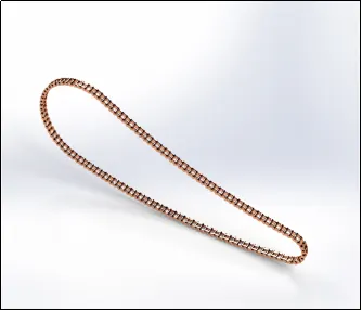
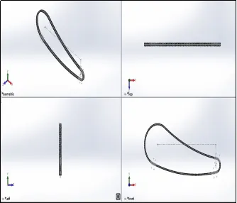
Fig 1.1 Render Image Fig 1.2 Part Image
Features Used: Block,Boss Extrude,Curve Driven Pattern
- CHASSIS
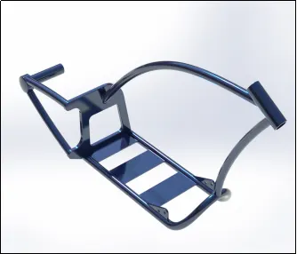
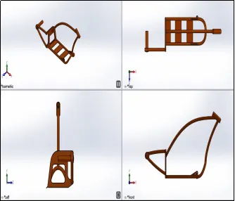
Fig 2.1 Render Image Fig 2.2 Part Image
Features Used: Projected curve,Boss Extrude,Revolve,Sweep,Mirror
- ENGINE
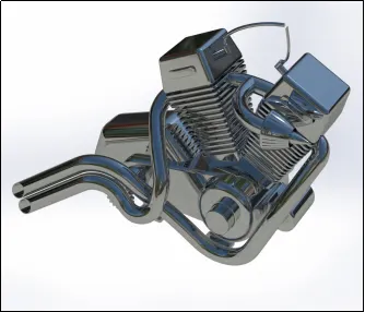
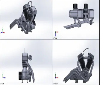
Fig 3.1 Render Image Fig 3.2 Part Image
Features Used: Projected curve,Composite curve,Linear Pattern,Circular Pattern,Revolve,Sweep,Boss Extrude,Cut Extrude.
- FRONT FENDER
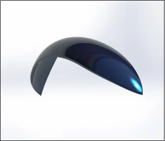
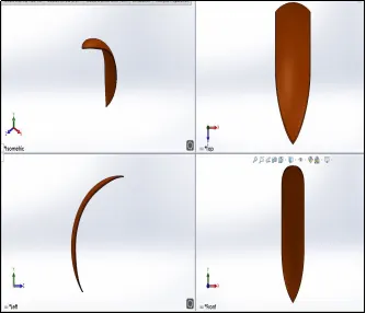
Fig 4.1 Render Image Fig 4.2 Part Image
Features Used: Fillet,Split,Revolve
- FRONT FORK
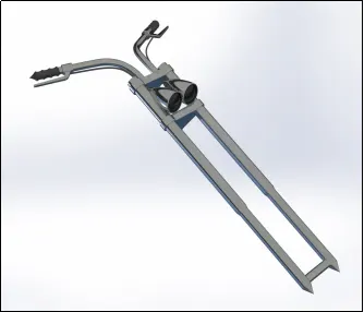
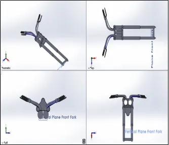
Fig 5.1 Render Image Fig 5.2 Part Image
Features Used: Projected curve,Sweep,Revolve,Boss Extrude,Mirror
- FRONT WHEEL
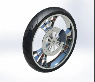
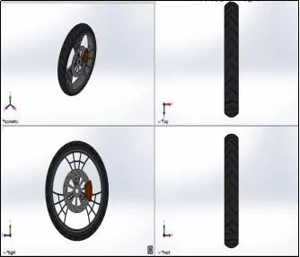
Fig 6.1 Render Image Fig 6.2 Part Image
Features Used: Revolve,Extrude Boss,Extrude Cut,Mirror,Circular Pattern
- GAS TANK
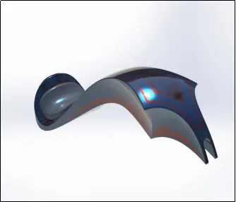
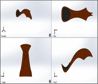
Fig 7.1 Render Image Fig 7.2 Part Image
Features Used: Projected Curve,Extrude Surface,Surface Sweep,Surface Sweep,Surface Fill
- KICK STAND
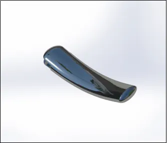
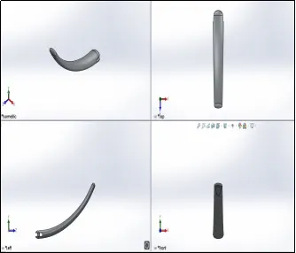
Fig 8.1 Render Image Fig 8.2 Part Image
Features Used: Dome,Loft
- OIL TANK
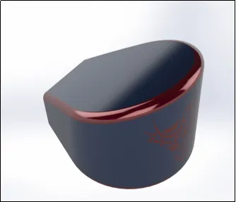
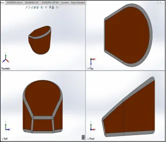
Fig 9.1 Render Image Fig 9.2 Part Image
Features Used: Boss Extrude,Fillet,Combine,Shell.
- PEDAL
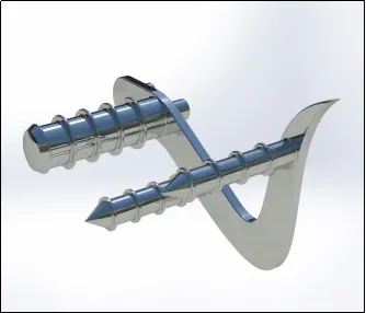
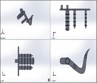
Fig 10.1 Render Image Fig 10.2 Part Image
Features Used: Boss Extrude,Linear Pattern,Fillet
- REAR FENDER
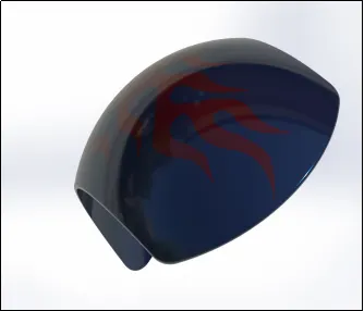
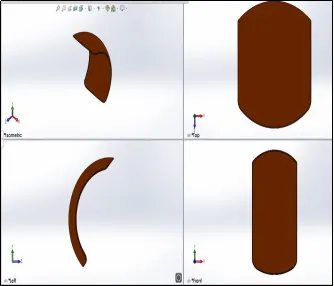
Fig 11.1 Render Image Fig 11.2 Part Image
Features Used: Fillet,Split,Revolve
- REAL WHEEL
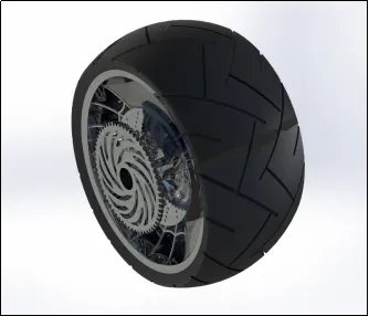
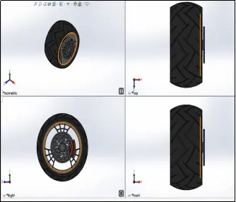
Fig 12.1 Render Image Fig 12.2 Part Image
Features Used: Revolve,Extrude Boss,Extrude Cut,Mirror,Circular Pattern
- TRANSMISSION BELT
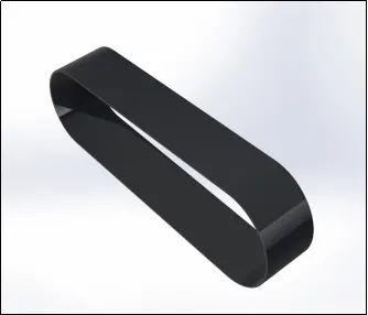

Fig 13.1 Render Image Fig 13.2 Part Image
Features Used: Boss Extrude,Offset,Fillet
ASSEMBLY
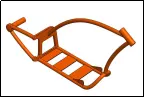
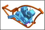
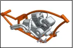
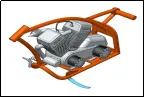
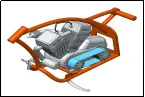
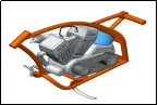
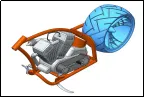
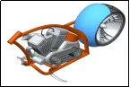
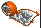
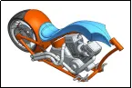
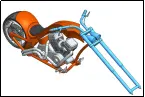
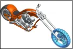
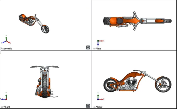
Fig B. Assembly American Chopper
Features Used: Mates : Coincidence,Concentric,Parallel,Distance,Angle.
RENDER-PHOTO VIEW 360 & SOLIDWORK VISUALIZE
Photo View 360 is a rendering and visualization solution included with Solid Works. It provides a highly interactive platform for viewing design and creating photo realistic renders.
Features: Environment Setup,Appearance Setup,Camera Setup,Lighting,Brightness
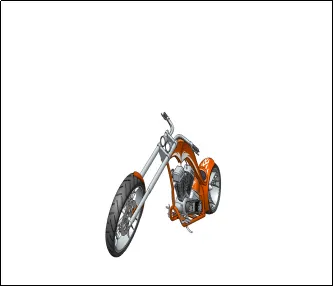
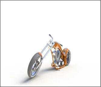
Fig C. Before and After Render
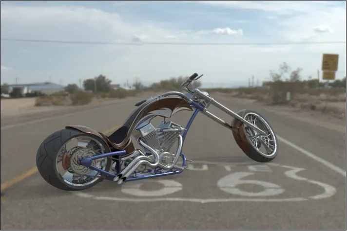
Fig D. Render-1 , Environment-Route 66
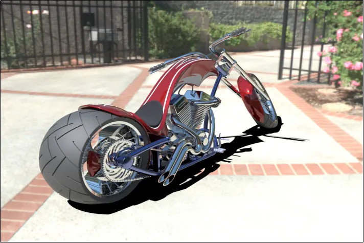
Fig E. Render-2 , Environment-Sunny Driveway
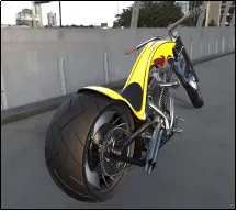
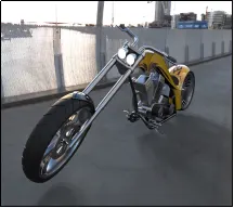
Fig D. Render-3 , Environment-Docklands Bridge
CONCLUSION
Used various tools and features of Solid Works to 3D model and assemble parts of a American Chopper. Used Photo View 360 to create a photo realistic Render.