Radar Mast & Final Assembly of Yacht
28/04/2021
OBJECTIVE
Modeling, Assembly and Photo Realistic render of Sunseeker Predator Yacht
Objective of this project is to create part drawings, convert them into 3D models, assemble the created parts in Solid Works and giving it a photo realistic render using photo view 360.
INTRODUCTION
Solid Works is a solid modeling CAD (Computer Aided Design) and CAE (Computer Aided Engineering) Software Published by Dassault Systems. It was developed by MIT graduate Jon Hirschtick and bought by Dassault Systems in 1997. Its a parametric modeling software in which you capture design intent using features and constraints.
DESCRIPTION
A yacht is a sail or power vessel used for pleasure, cruising, or racing.There is no standard definition, so the term applies to such vessels that have a cabin with amenities that accommodate overnight use.
Sunseeker International is a British luxury performance motor yacht brand. Originally named Poole Power Boats, the company was founded by brothers Robert and John Braithwaite in 1969. The company changed its name to Sunseeker International in 1985 and has since become a global icon.
The Sunseeker Predator Yacht created in this project consists of 9 individual parts,namely:
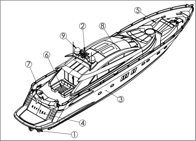
Fig A. Parts of Sunseeker Predator Yacht
|
Sno |
Description |
Purpose |
Material |
Quantity |
|
1 |
Propeller |
propel the ship by using the power generated |
alloy of aluminium and stainless steel. |
1 No |
|
2 |
Radar |
Aid to navigation; used in identifying,tracking and positioning |
Carbon fiber |
1 No |
|
3 |
Hull |
structural entity of the ship |
Aluminum,Wood and composite |
1 No |
|
4 |
Garage Door |
To close the garage space. |
Metal |
1 No |
|
5 |
Front Seat |
Something used to sit on |
Foam,Cotton,Leather |
1 No |
|
6 |
Middle Seat |
Something used to sit on |
Foam,Cotton,Leather |
1 No |
|
7 |
Rear Seat |
Something used to sit on |
Foam,Cotton,Leather |
1 No |
|
8 |
Superstructure |
extended construction of a yacht |
Aluminum,Wood and composite |
1 No |
|
9 |
Radar Mast |
Support Radar and communication equipment |
Carbon fiber |
1 No |
Table A. BOM
DESIGN METHODOLOGY
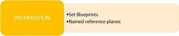

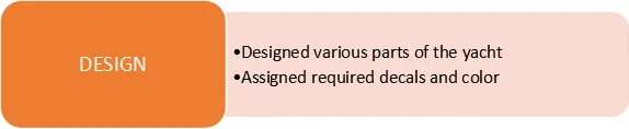
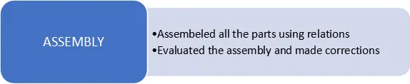
PART MODELING
1.PROPELLER
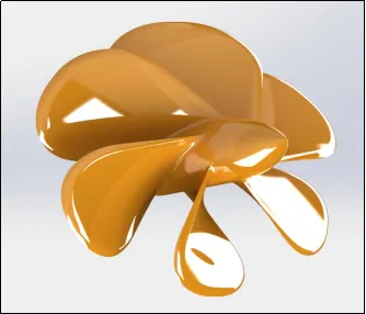
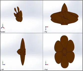
Fig 1.1 Render Image Fig 1.2 Part Image
A Propeller is a rotating fan like structure used to propel the ship by using the power generated and transmitted by the main engine of the ship. Marine propellers are made from corrosion resistant materials as they are made operational directly in sea water.The materials used for making marine propeller are an alloy of aluminium and stainless steel.
Design approach
- Created a fully defined sketch.
- Used the Revolved Boss/Basefeature along the center axis to create a 3D solid body.
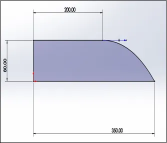
- Created a fully defined3 point rectangle on the Right plane.
- Created areference plane and defined the required distance.
- Created a 2D sketch (3 point rectangle) on the new plane and fully defined the dimensions.
- Used the Lofted Boss/Basefeature to generate a 3D solid connecting the 2 sketches defined.
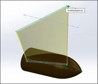
- Applied fillet feature along the edges.
- Used the circular pattern featureand created 6 instances taking the revolved body as the axis.
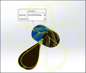
- Applied the required appearance.
PROPELLER - USER DEFINED VALUE COLOR
2.RADAR
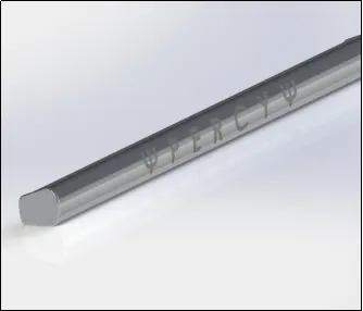
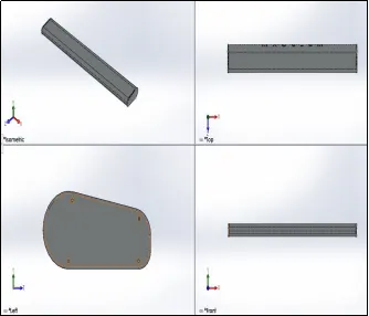
Fig 2.1 Render Image Fig 2.2 Part Image
The word RADAR stands for RAdio Detection And Ranging. It is a mandatory aid to navigation; used in identifying,tracking and positioning of the vessel to safely navigate a body from one point to another.The marine radar works on the basic principle of electromagnetic waves.
Design approach
- Created a fully defined sketch by defining all the required dimensions.
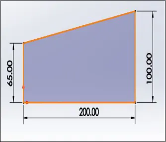
- Used the Extrude Boss/Base feature to create 3D solid body.
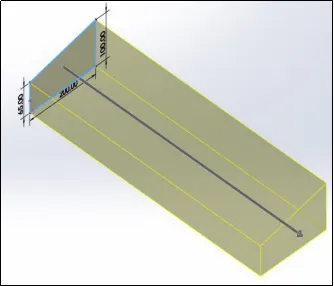
- Used the Fillet feature around the edges.
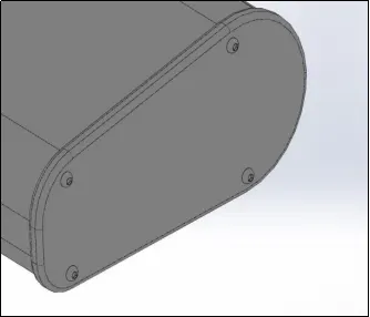
- Creates a new sketch on the side face to define the side plate and Round Head screws.
- Extruded cut feature was used to create the allen socket on the round head screw
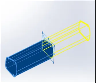
- Used the Mirror feature as the right plane as the reference to create a mirror of the selected feature.
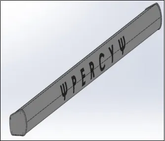
- Created a construction line to insert text.
- Text was inserted by using the Text option in sketch entities under tool menu.
- Applied the required appearance.
RADAR - USER DEFINED VALUE COLOR
3.HULL
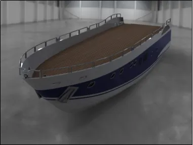
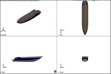
Fig 3.1 Render Image Fig 3.2 Part Image
The hull of a ship is the most notable structural entity of the ship. To define the hull, it can be said that it is the watertight enclosure of the ship, which protects the cargo, machinery, and accommodation spaces of the ship from the weather, flooding, and structural damage. There are various shapes for hull. "V-shaped" hulls are planing hulls, and are the most common type of hull for powerboats.
Section 1
Design Approach
- A composite curvewas created using two projected curve to develop the surface of the hull.
- Extend surface, Trim surface features were used to develop surface as needed.
- Surface fill feature was used to close the surface, knitted the surface and created a solid out of the hollow body.
- Used theshell command and defined the required thickness for the body.
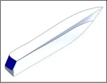
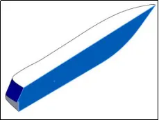
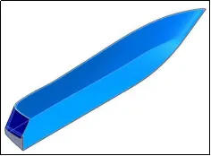
Fig 1.1 Fig 1.2 Fig 1.3
Section 2
Design Approach
- Boss extrude feature was used to create the deck of the hull by setting the direction to the inside surface.
- Cut Extrude, Boss Extrude, Fillet, Chamfer featurewere used to attain the required model.
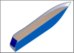
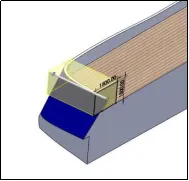
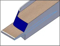
Fig 2.1 Fig 2.2 Fig 2.3
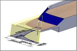
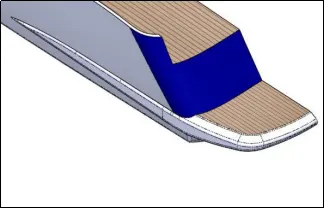
Fig 2.4 Fig 2.5
Section 3
Design Approach
- Cut Extrude featurewas used to define the windows on the outside surface of the hull.
- The rims of the window was created using the sweep feature by defining a sketch and a path. 3D sketch toolwas used to define the sketch for path.
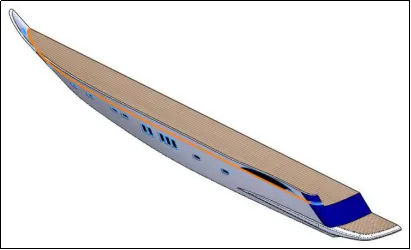
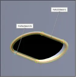
Fig 3.1 Fig 3.2
Section 4
Design Approach
- Cut extrudefeature was used to create a cut out to develop the stairs.
- Boss extrudefeature was used to create stairs from a fully defined sketch
- Fillet feature was used to smooth the sharp edges.
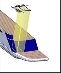
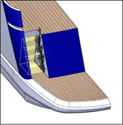
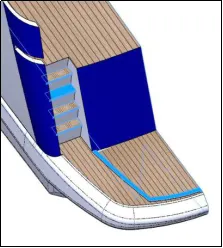
Fig 4.1 Fig 4.2 Fig 4.3
Section 5
Design Approach
- The Keelof the yacht was created using the Boss extrude feature and setting the direction to upto surface in the reverse direction.
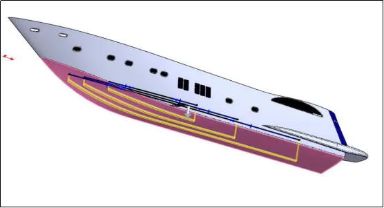
Fig 5.1
Section 6
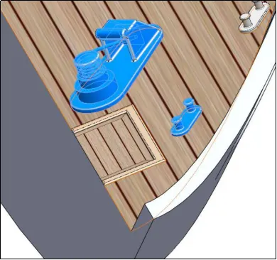
Fig 6.1
Design Approach
- The winch and ropeswere created used the Box extrude,Cut extrude,Helix spiral,Sweep and Dome
Section 7
Design Approach
- A composite curve was created using twoprojected curve to define the path for the railings.
- A plane was created normal to the pathand a fully defined sketch of a circle was created.
- Sweep Feature was used to create the railings.
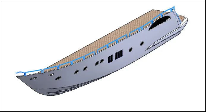
Fig 7.1
Section 8
Design Approach
- The Hub of the propeller were created using the Revolve feature.
- Boss Extrude, Cut Extrude ,Thin Extrude, Fillet and Chamferfeatures were used to model various aspects of the body.
- Mirror featurein pattern was used to create a mirror body of the required feature.
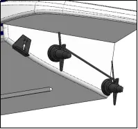
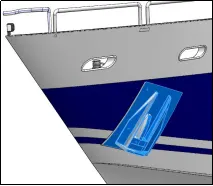
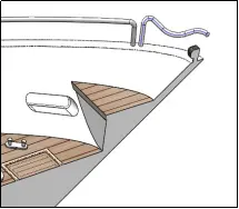
Fig 8.1 Fig 8.2 Fig 8.3
Section 9
Design Approach
- Cut extrude feature was used to separate out a portion from the hull.
- Split Feature was used to separate the cut out body from the hull. It was saved as part modelto later develop the garage door.
- Revolve featurewas used to create a hinge pin to support the garage door.
- Mirror featurewas used to create a mirror of the entire hull body.
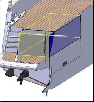
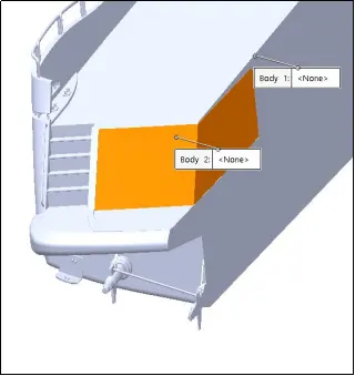
Fig 9.1 Fig 9.2
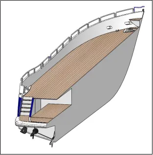
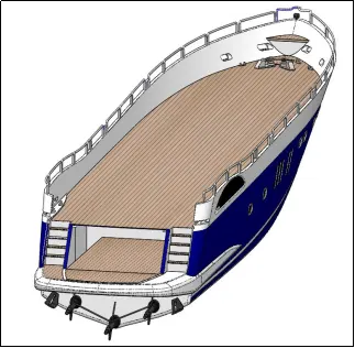
Fig 9.3 Fig 9.4
4.GARAGE DOOR
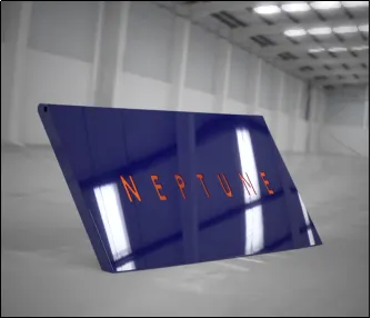
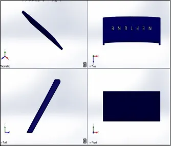
Fig 4.1 Render Image Fig 4.2 Part Image
Design Approach
- The split saved as stock from the hull was imported to create the garage door of the yacht.
- Cut extrudefeature was used to remove the unwanted feature.
- Cut extrudefeature was used to create a hinge hole to accommodate the hinge pin.
- Chamfer and Fillet feature was used to smooth the sharp edges and attain the require model.
- Mirror featurewas used to get a reflection the required body.
- Cut extrude of a text sketchwas used to cut out the name of the yacht onto the surface of the garage door.
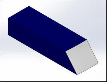
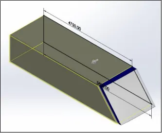
Fig 1.1 Fig 1.2
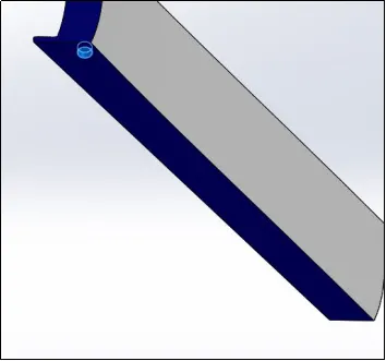
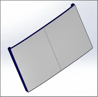
Fig 1.3 Fig 1.4
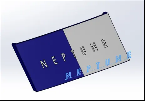
Fig 1.5
5.FRONT SEAT
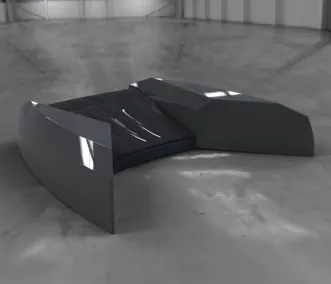
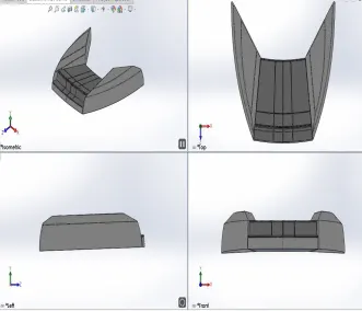
Fig 5.1 Render Image Fig 5.2 Part Image
Design Approach
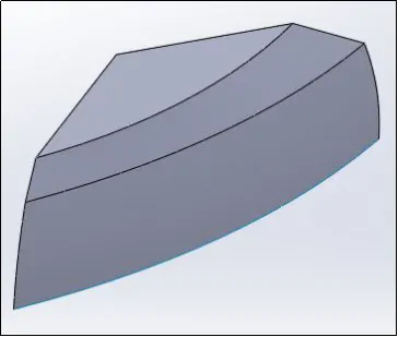
Fig 1.1
- The Offset surface of the deck from the hullis used as the reference for the modeling of the front seat.
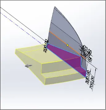
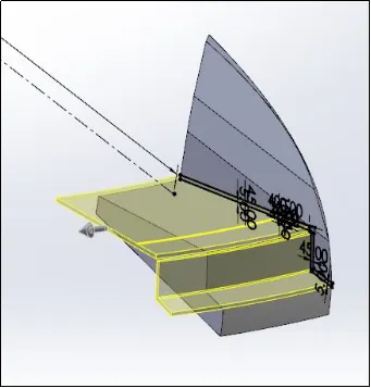
Fig 1.2 Fig 1.3
- Surface Sweep,Surface Extrude,Surface Trim,Surface Fill, Surface loftfeatures were used to attain the required model.
- Surface knitcommand was used to close all the gaps between the surfaces and create a solid model.
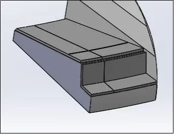
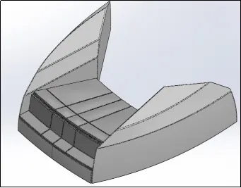
Fig 1.4 Fig 1.5
- Mirror Featurewas used to create a reflection of the required body.
- Dome featurewas used to imitate as cushion for the seats.
6. MIDDLE SEAT
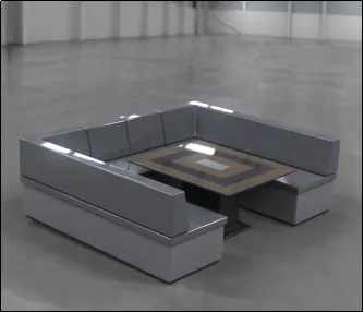
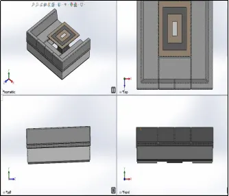
Fig 6.1 Render Image Fig 6.2 Part Image
Design Approach
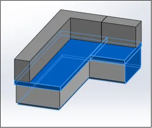
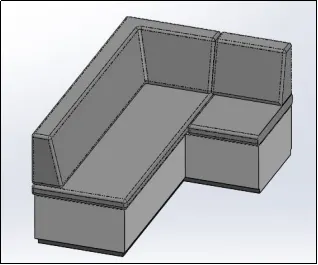
Fig 2.1 Fig 2.2
- The Offset surface of the deck from the hullis used as the reference for the modeling of the Middle seat.
- Boss Extrude featurewas used to develop solid body from fully defined sketch to model the seat
- Chamfer and Fillet featureswere used to smooth sharp edges.
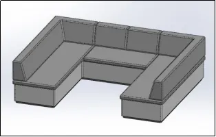
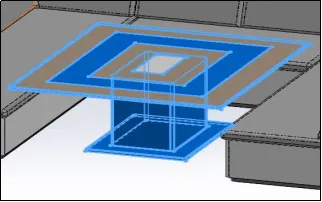
Fig 2.3 Fig 2.4
- Mirror Featurewas used to create a reflection of the required body.
- Boss Extrude and Cut Extrudefeatures were used to model the table.
7.REAR SEAT
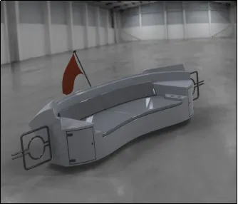
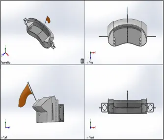
Fig 7.1 Render Image Fig 7.2 Part Image
Design Approach
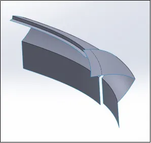
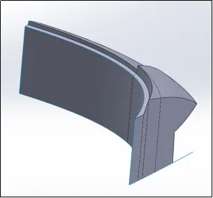
Fig 3.1 Fig 3.2
- The Offset surface of the deck from the hullis used as the reference for the modeling of the Rear seat.
- Surface Sweep,Surface Extrude,Surface Trim,Surface Fill, Surface loft and Ruled Surface features were used to attain the required model.
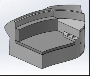
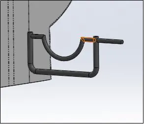
Fig 3.3 Fig 3.4
- Boss Extrude and Boss Cutfeatures were used to model the cushion of the rear seat.
- Swept boss featurewas used to model the gate attached to the seat.
- Mirror featurewas used to reflect the gate along the appropriate axis.
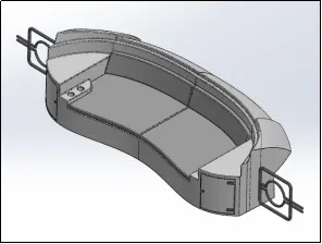
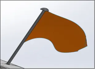
Fig 3.5 Fig 3.6
- 3D sketch toolwas used to draw splines that define the outline of the flag.
- Surface Loft featurewas used setting the 3D sketch as the boundary.
- Revolve commandwas used for the flag post.
8. SUPERSTRUCTURE
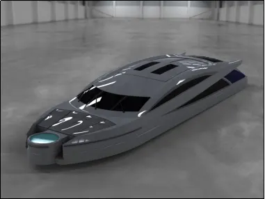
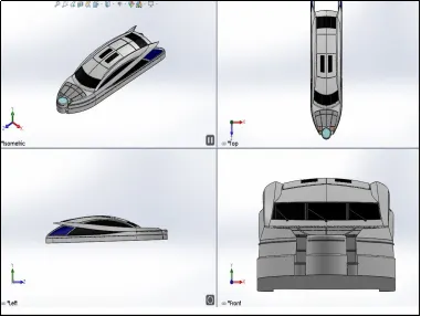
Fig 8.1 Render Image Fig 8.2 Part Image
SUPER STRUCTURE
A superstructure is an extended construction of a yacht that rises above the deck in a distinct manner. The word comes from a combination of two Latin words, the Latin prefix ‘super’ means in addition or above or in excess of, whereas the stem word ‘structure’ means to build or to heap up. The size of the superstructure has a great influence on the mobility of the vessels. They are designed in a manner, so that, they add value and hinder the speed and mobility in the least. The superstructure is mostly designed in fashion as well.
Section 1
Design Approach
- The offset surfaceof the deck was used as reference to model the superstructure.
- Surface Extrude , Surface Sweep , Ruled Surface , Surface Trim , Surface Loft , Surface Fillfeatures were used to attain the required model.
- 3D sketchtool was used to sketch lines and splines on the 3D plane.
- Surface Knitfeature was used to close the gaps between the surfaces.
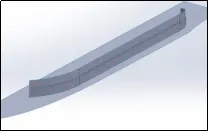
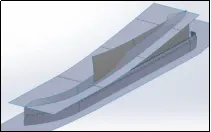
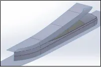
Fig 1.1 Fig 1.2 Fig 1.3
Section 2
Design Approach
- The top of the superstructure was modeled using the Surface loft feature.
- Surface Extend was used to extend the existing surfaces.
- Ruled surfaceand Surface trim option was used to attain the required model.
- Surface knitfeature was used to close all the gaps between the surfaces
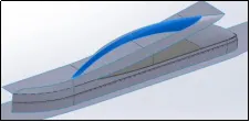
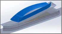
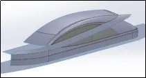
Fig 2.1 Fig 2.2 Fig 2.3
Section 3
Design Approach
- Surface Extrudefeature was used to model the back door frame.
- The front of the superstructure was modeled using the Surface loft , Surface sweep , Surface trim features.
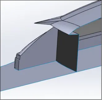
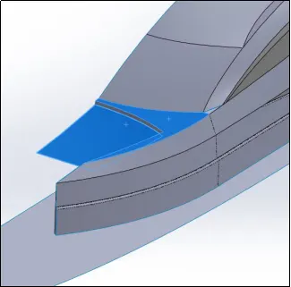
Fig 3.1 Fig 3.2
Section 4
Design Approach
- The Jacuzziat the front was modeled using the Boss extrude , cut extrude feature by sketching fully defined sketches.
- Fillet and chamfertools were used to smooth the sharp edges.
- The Stairs were modeled by using the Surface Extend , Surface trim , Surface Sweep
- Surface knitfeature was used to close all the gaps between the surfaces
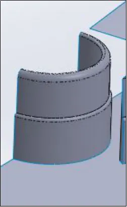
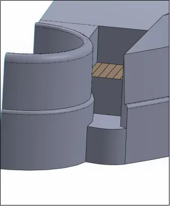
Fig 4.1 Fig 4.2
Section 5
Design Approach
- The open surface of the super structure was closed using the surface extrude and surface trim
- Surface knit was used to close the gaps and to create a solid out of the surface model. All boundarieswere checked to have black lines suggesting all surface are well knitted.
- Thicken feature was used to define the required thickness to model the front glass panes.
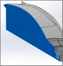
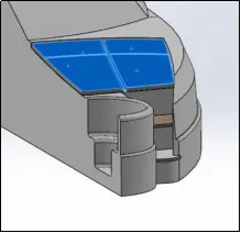
Fig 5.1 Fig 5.2
Section 6
Design Approach
- Dome Feature was used to give the embossed effect on the front window panes.
- Extend surfacewas used to model the handle on the back door.
- Sweep and Cut extrudewere used to provide detailing on the front and back panes.
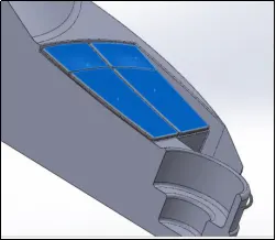
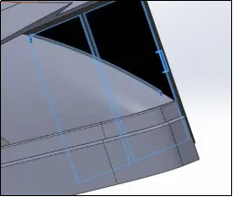
Fig 6.1 Fig 6.2
Section 7
Design Approach
- The partition for the side windows was modeled using a fully defined sketchand using the surface extrude feature setting the direction upto surface.
- Cut Extrude and Boss extrude feature was used to create cut out for the window panes.
- Split Line Featurewas used to separate two surface along the sketch.
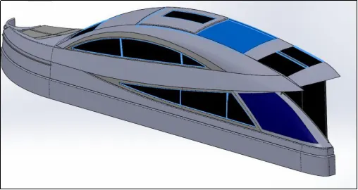
Fig 7.1
Section 8
Design Approach
- Surface extrude featurewas used to model the water level of the Jacuzzi.
- Boss Extrudefeature was used to model the windscreen wiper hinge. Fillet was used to smooth the sharp edges.
- Mirror Feature was used to create a reflection of the entire body.
- Surface offsetwas used to define was reference surface to later model the radar mast.
- Boss extrude,cut extrude, chamferfeatures were used to model the wind screen wiper.
- 3D sketch tool was used to create path that connect hinge to the wiper. Boss Extrudewas create along the sketch.
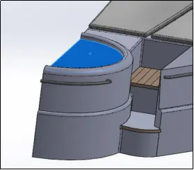
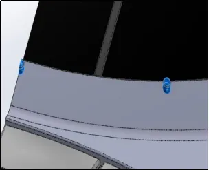
Fig 8.1 Fig 8.2
- Thephoto view 360 was included to add decals to the required parts of the superstructure.
- Colour was set at required faces as per selection.
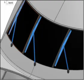
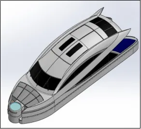
Fig 8.3 Fig 8.4
9.RADAR MAST
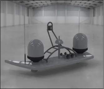
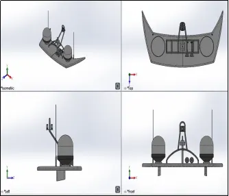
Fig 9.1 Render Image Fig 9.2 Part Image
Feature Tree
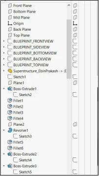
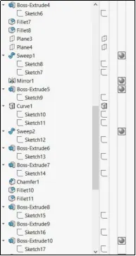
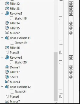
Design Approach
- The offset surfacefrom the superstructure was use as the reference to create a plane to model the base of the Radar Mast.
- Boss Extrudefeature was used to model the base from a fully define sketch.
- Fillet featurewas used to smooth the sharp edges.
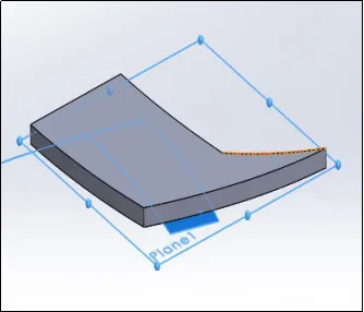
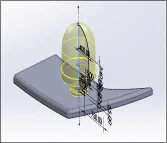
Fig 1.1 Fig 1.2
- Revolve feature was used to model the radar.
- Boss extrude featurewas used to model the
- Sweep featurewas used to model the rails and boss extrude feature for lights.
- Mirror feature was used to replicate the desired body across the rails.
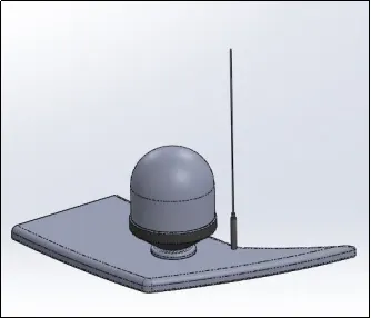
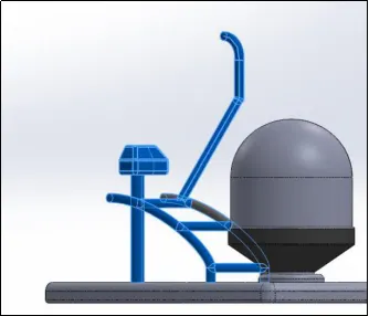
Fig 1.3 Fig 1.4
- Revolve and Domefeature was used to model the Fog horn.
- The entire body was replicated across the mid plane using the mirror feature.
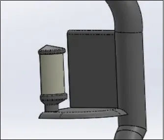
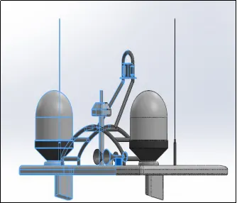
Fig 1.5 Fig 1.6
ASSEMBLY
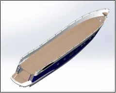
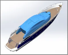
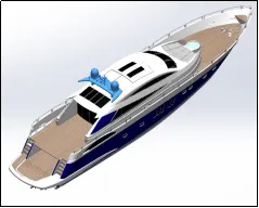
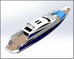
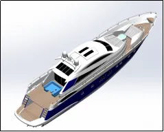
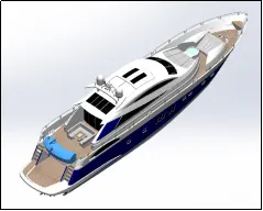
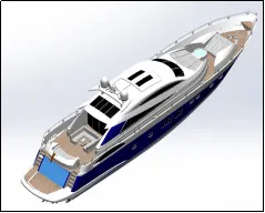
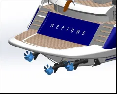
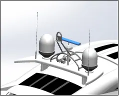
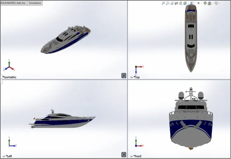
Fig B. Assembly Sunseeker Predator Yacht
RENDER-PHOTO VIEW 360
Photo View 360 is a rendering and visualization solution included with Solid Works. It provides a highly interactive platform for viewing design and creating photo realistic renders.
Features: Environment Setup,Appearance Setup,Camera Setup,Lighting,Brightness
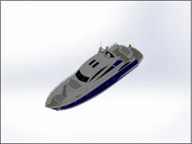
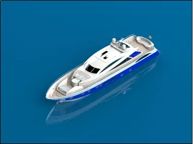
Fig C. Before and After Render
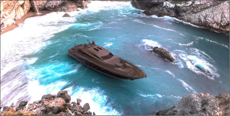
Fig D. Render Solidworks Visualize
CONCLUSION
Completed modelling and assembly of Sunseeker Predator Yacht, Rendered the assembly using photo view 360 and Solidwork Visulaize.