Advanced Sheet Metal Design Using NX Cad Challenge_6_Bracket
BRACKET
OBJECTIVE
To model the Bracket using Siemens NX software by sheet metal tool.
INTRODUCTION
The sheet metal can be bent, drawn, cut, punched, or stretched. These processes are responsible for forming the metal into a different shape, surface, or size.
Here, By using Siemens NX Software the sheet metal Bracket is done.
DESIGN METHODOLOGY
FEATURE SEQUENCE/FLOW
MIRROR CURVE
- It is used to make a mirrored copy of sketch geometry through a specified sketch.
- Insert - sketch curve - Mirror curve
CONTOUR FLANGE
- It is used to create a flange by extruding a sketch along a vector, or by sweeping a sketch along an edge or chain of edges. NX adds the contour flange as the base feature of a new sheet metal part, or add the contour flange as a secondary feature.
- Menu - Insert - bend - contour flange
NORMAL CUTOUT
- It cuts the material by projecting a sketch onto the model and then cutting perpendicular to the faces intersected by the projection.
- Insert - cut - Normal cutout.
BREAK CORNER
- It used to round or chamfer sharp corners of a tab or flange.
- Insert - corner - Break corner
UNBEND
- It used to unbend a portion of the part to construct cutout features, hole features, or deform features across a bend.
- Insert - Form - Unbend
BEAD
- It used to lift material along the contour of a sketch that simulates a stamping tool. Beads can also be created to stiffen sheet metal parts.
- Insert - punch - Bead
REBEND
- It is used to reverse an unbend operation so that the feature that was unbent returns to its previous bent state. Any features added after the unbend operation are properly repositioned during the rebend operation.
- Insert - form - rebend
HOLE
- It used to add the following types of hole features in a part or assembly:
- General holes (simple, counterbored, countersunk, or tapered... )
- Drill Size holes
- Screw Clearance holes (simple, counterbored, or countersunk form)
- Threaded holes
- Holes on non-planar faces.
- Insert - Design feature - Hole
FLAT PATTERN
- It is used to create a 2D representation of the flattened 3D sheet metal part.
- Insert - flat pattern - flat pattern
MODEL IMAGES
Front View
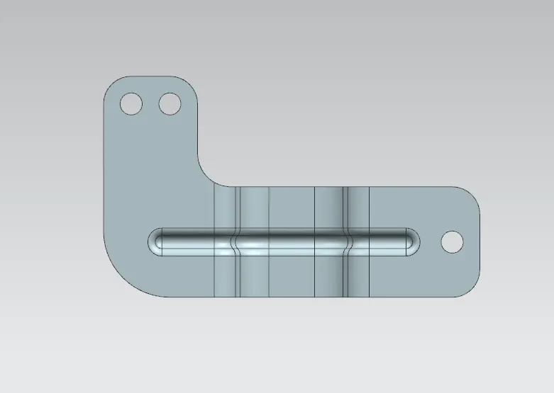
Top View

Side View
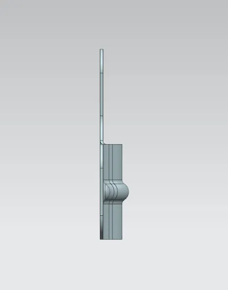
Isometric view
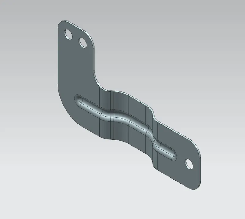
Drawing
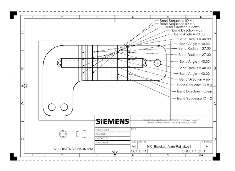
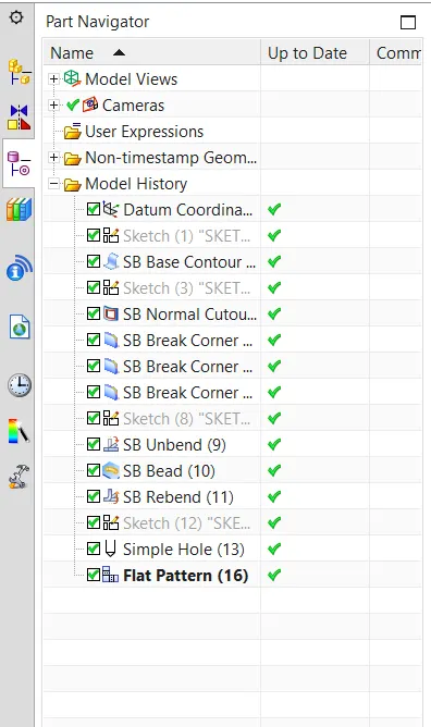
Model Tree
CONCLUSION
Thus the Bracket using NX software by sheetmetal tool is done. And the results are obtained.