Advanced Sheet Metal Design Using NX Cad Challenge_2_Box Assembly
BOX ASSEMBLY
OBJECTIVE
To model the box assembly using NX software sheet metal tool.
INTRODUCTION
The sheet metal can be bent, drawn, cut, punched, or stretched. These processes are responsible for forming the metal into a different shape, surface, or size.
Here, By using Siemens NX Software the sheet metal Box Assembly is done.
DESIGN METHODOLOGY
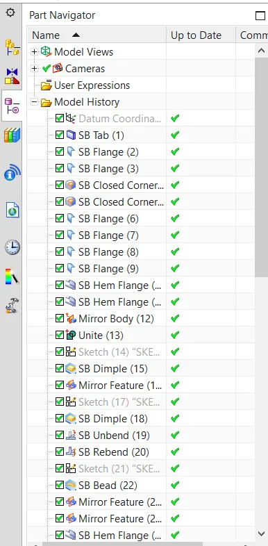
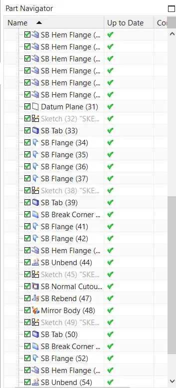
FEATURE SEQUENCE/FLOW
1. Tab
2. Flange 2
3. Closed corner 2
4. Flange 4
5. Hem Flange 2
6. Mirror Curve
7. Mirror Body
8. Unite
9. Dimple
10. Mirror Feature
11. Dimple
12. Unbend
13. Rebend
14. Bead
15. Mirror Feature 2
16. Hem flange 6
17. Datum plane
18. Tab
19. Flange 4
20. Tab
21. Break corner
22. Flange 2
23. Hem flange
21. Unbend
22. Normal cutout
23. Rebend
24. Mirror Body
25. Tab
26. Break Corner
27. Flange
28. Hem Flange
29. Unbend 2
30. Normal Cutout
31. Rebend
32. Flat pattern
DESCRIPTION
TAB
- It creates a base feature by extruding a sketch along a vector by a thickness value or adds a material to a planar face.
- Insert - Tab
FLANGE
- It creates a single flange instance or multiple instances by selecting a single or multiple base edges.
- Insert - Bend - Flange
CLOSED CORNER
- It is used to modify two flanges in one operation and to close the corner where the two flanges meet. During flattening, the corner and relief geometry are made appropriate for a flat pattern.
- Insert - corner - closed corner
- Types - Open,Closed,Circular Cutout,V cutout, U cutout, Rectangular cutout
HEM FLANGE
- It is used to modify an edge of a sheet metal part by folding it onto itself for the purpose of safe handling or to increase edge stiffness. The hem flange is always created as a secondary feature on a base part. You can create hem flanges on: Linear edges and curved edges of the curves that include a curved edge.
- Insert - bend - Hem flange
MIRROR CURVE
- It is used to make a mirrored copy of sketch geometry through a specified sketch.
- Insert - sketch curve - Mirror curve
MIRROR BODY
- It is used to mirror a sheet metal body about an existing datum plane. If a suitable datum plane does not exist, you must first create one using the Datum Plane command.
- Insert - Associative copy - Mirror Body
UNITE
- It is used to unite sheet metal bodies. As the sheet metal characteristics are retained during the unite operation.
- Insert - Combine - unite
DIMPLE
- It is used to lift an area of the model inside a sketch that simulates a stamping tool.
- Insert - punch - dimple
MIRROR FEATURE
- It used to mirror one or more selected features about a selected datum plane or planar face. It can also mirror selected of a pattern instead of the entire pattern.
- Insert - Associative copy - Mirror feature
UNBEND
- It used to unbend a portion of the part to construct cutout features, hole features, or deform features across a bend.
- Insert - Form - Unbend
REBEND
- It is used to reverse an unbend operation so that the feature that was unbent returns to its previous bent state. Any features added after the unbend operation are properly repositioned during the rebend operation.
- Insert - form - rebend
BEAD
- It used to lift material along the contour of a sketch that simulates a stamping tool. Beads can also be created to stiffen sheet metal parts.
- Insert - punch - Bead
DATUM PLANE
- It is used to create a planar reference feature to help define other features, such as swept bodies and features at angles to the faces of target solids.
- Insert - Datum/point - Datum plane
BREAK CORNER
- It used to round or chamfer sharp corners of a tab or flange.
- Insert - corner - Break corner
NORMAL CUTOUT
- It cuts the material by projecting a sketch onto the model and then cutting perpendicular to the faces intersected by the projection.
- Insert - cut - Normal cutout.
FLAT PATTERN
- It is used to create a 2D representation of the flattened 3D sheet metal part.
- Insert - flat pattern - flat pattern
MODEL IMAGES
Front View
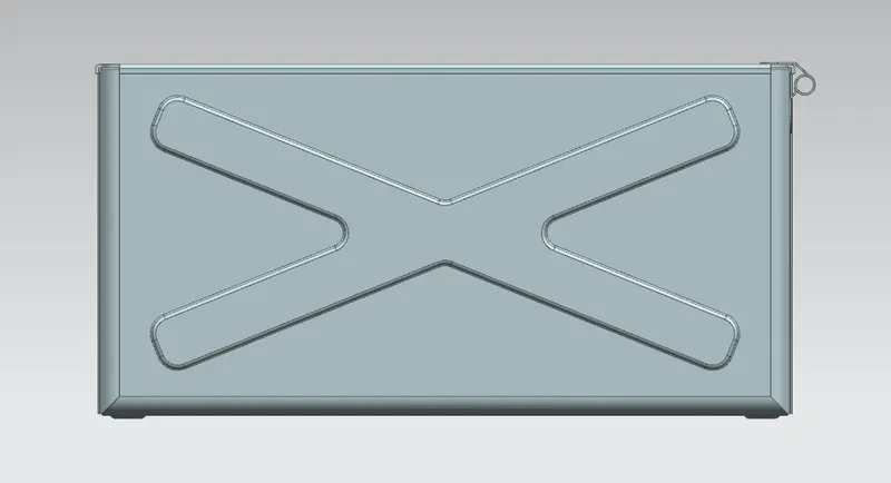
Top View
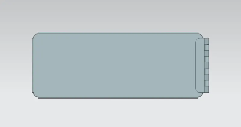
Side View
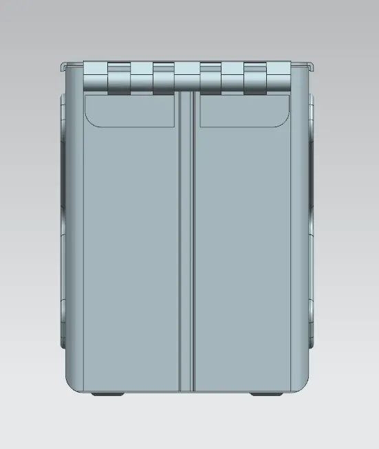
Isometric View
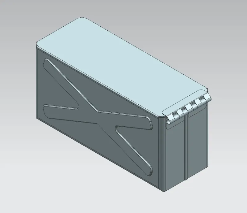
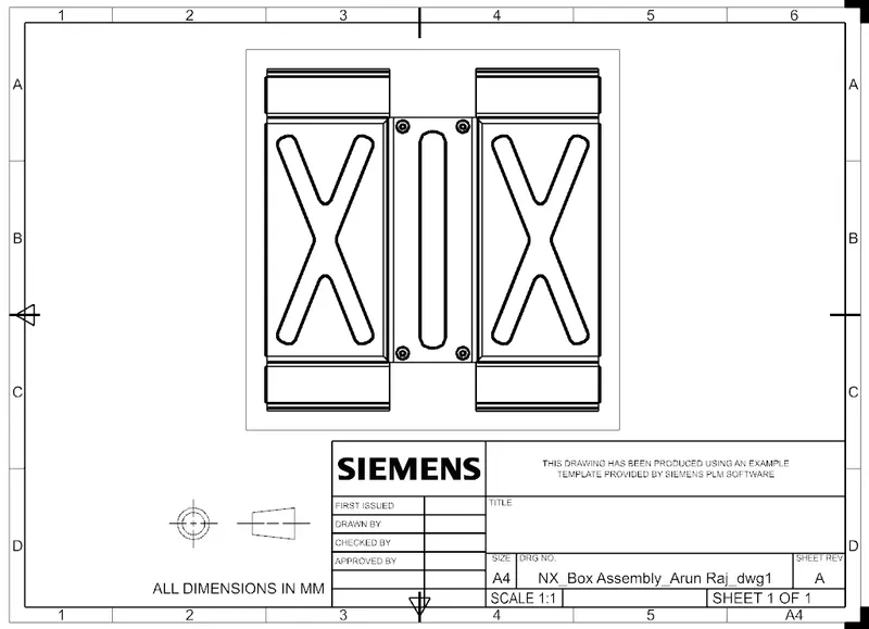
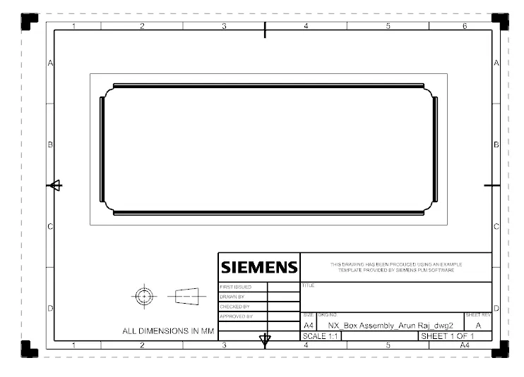
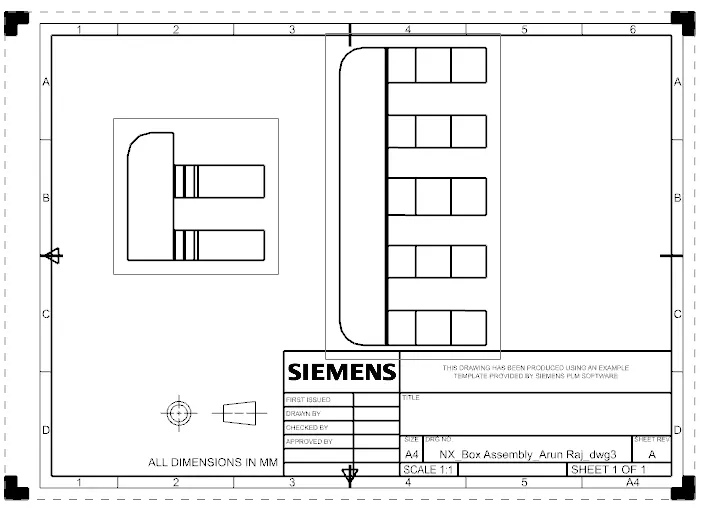
DRAWING IMAGES
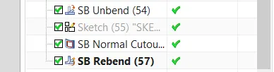
Model Tree
CONCLUSION
Thus the Box Assembly using NX sheet metal software is done. And the results are obtained.